Advertisement
Quick Links
Advertisement

Subscribe to Our Youtube Channel
Related Manuals for ClientPOS PT6000

Summary of Contents for ClientPOS PT6000
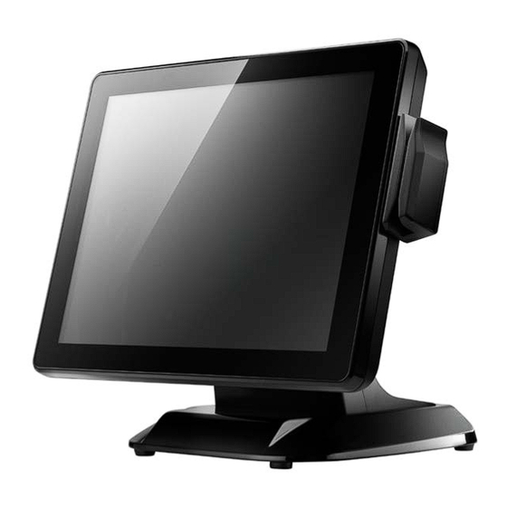
- Page 1 PT6000 User Manual Version: 2.0 P/N : Cover Page Cover page 1 | 8 0...
- Page 2 ClientPOS PT6000 User Manual Version: 2.0 Copyright Copyright 2010 Publishing. All Rights Reserved. This manual, software and firmware described in it are copyrighted by their respective owners and protected under the laws of the Universal Copyright Convention. You may not reproduce,...
-
Page 3: Safety Instructions
ClientPOS PT6000 User Manual Version: 2.0 Safety Instructions Read these instructions carefully. Keep these instructions for future reference. Please disconnect this equipment from AC outlet before cleaning. Don’t use liquid or sprayed detergent for cleaning. Use moisture sheet or cloth for cleaning. - Page 4 ClientPOS PT6000 User Manual Version: 2.0 Table of Contents 1. Packing List……………………………………………… Standard Accessories……………………………………….. Optional Accessories………………………………………... 2. System View ……………………………...………. …… Rear View…………………………………………………….. Specification………………………………………………….. Internal Layout……………………………………………….. 3. Pin Definition……………………………………………... 4. Rear I/O Interface…………………..…………………… 5. System Assembly & Disassembly…………………… HDD…………………………………………………………..CF Card……………………………………………………….
- Page 5 ClientPOS PT6000 User Manual Version: 2.0 Packing List Packing List Standard Accessories System (with stand) Power Adapter Power Cord Driver Bank Screw x2 Cable Cover Optional Accessories a. Single MSR b. 3 IN 1 MSR c. UPS Battery d. Screw x2...
- Page 6 ClientPOS PT6000 User Manual Version: 2.0 System View System View 2-1 Rear View with Optional LPT Port Rear View Standard Item 19V DC Input PS2(K/B) RJ45(COM 4 for External VFD) UPS Battery(Option) COM2 COM3 USB 2.0/1.1 X4 RJ45(LAN) 10. RJ11(Cash Drawer) 11.
- Page 7 ClientPOS PT6000 User Manual Version: 2.0 2-2 Specification Intel® Atom™ processor D525 (1M Cache, 1.80GHz) Processor Chipsets: North Bridge/South ICH8-M Bridge Memory One SO-DIMM socket supports DDR3 800 up to 4GB Audio Line-out/Mic-in Network RJ45 10/100/1000 Base-T 4*USB 2.0 Storage CF card / 2.5”...
- Page 8 ClientPOS PT6000 User Manual Version: 2.0 Internal Layout 8 | 80...
- Page 9 ClientPOS PT6000 User Manual Version: 2.0 Pin Definition Pin Definition 1. COM 5 for Touch Panel (CN 16) Pin NO. Function Function Function T_UR T_SG T_LR T_UL T_LL 2. Parallel J7 Pin Name Description Pin NO. Pin Name Description STB#...
- Page 10 ClientPOS PT6000 User Manual Version: 2.0 5. Mic Pin Name Description Ground Ground Mic R Mic L Detect Detect 6. Speaker SP1 Pin Name Description Speaker + Speaker - 7. LVDS CN 2 Pin Name Description Pin NO. Pin Name...
- Page 11 ClientPOS PT6000 User Manual Version: 2.0 Rear I/O Interface Rear I/O Interface 1. COM1’ COM2’ COM3 port Signal Function Signal Function Carrier Detect (IN) Data Set Ready (In) Receive Data (IN) Request To Send (OUT) Transmit Data(OUT) Clear To Send (IN)
- Page 12 ClientPOS PT6000 User Manual Version: 2.0 3. USB port Signal Name Wire Colour Comment Cable Power - Data White Data Transfer + Data Green Data Transfer Ground Black Cable Ground Shell Shield Drain Wire 4. PS/2 K/B port Signal Name...
- Page 13 ClientPOS PT6000 User Manual Version: 2.0 System Assembly & Disassembly System Assembly & Disassembly 1. Unfasten the HDD cover screw*2 2. Pull out the HDD bracket 3. Fasten the screw*4 4. Place the HDD bracket back to the module 5-2 CF Card 1.
- Page 14 ClientPOS PT6000 User Manual Version: 2.0 2. Before Installing CF Card. 3. After Installing CF Card. 14 | 80...
- Page 15 ClientPOS PT6000 User Manual Version: 2.0 1. Open the MSR cover 2. Single MSR or 3-in-1 3. Screw*2 M3x10L 4. Fasten the screw 5-4 UPS Battery Paste two rubbers on the located position of the Stand Bracket. Reeve two cable ties through the stand bracket. Place the battery pack in position and bind the cable ties tightly.
-
Page 16: Cable Cover
ClientPOS PT6000 User Manual Version: 2.0 cable cover Assemble the cable cover from bottom and make sure the two latches are on the right position. Then fasten 2 screws (M3*5L). 5-6 15” 2 Display ☆ Power supply must be replaced to 120W above power adapter. - Page 17 ClientPOS PT6000 User Manual Version: 2.0 2. Install the pole into the socket in clockwise direction. 3. Fasten the four screws (M4*8L) to joint the VESA bracket and the rear cover. 4. Connect the COM port, DC cable as shown in figure .
- Page 18 ClientPOS PT6000 User Manual Version: 2.0 7. Assemble the cable cover from bottom and make sure the two latches are on the right position, and fasten the two screws (M3*5L). Route the cables through the opening of stand front cover and cable clip at the bottom and route the cables into the tube of pole.
- Page 19 ClientPOS PT6000 User Manual Version: 2.0 10. Mount the VESA bracket on the pole and route cables out of the tube of VESA bracket. Fasten the thumb screw to fix the VESA bracket. 11. Connect the DC power cable as shown in figure.
- Page 20 ClientPOS PT6000 User Manual Version: 2.0 5-7 Internal VFD ClientPOS electronics Model PT6000 Assembling Figure Inc. Operation VFD MODULE assemblely Item Operation procedure Remark Prepare all components as Fig 1 Assemble HOLDER & HINGE ASSY by TAPPING SCREW P/H 2.6φ*5 x2 pcs(As Fig 2) Torque 2Kgf Fix VFD MODULE on holder assy by TAPPING SCREW P/H 2.6φ*5 x4 pcs as Fig 3...
- Page 21 ClientPOS PT6000 User Manual Version: 2.0 5-8 Wi-Fi Fasten antenna (Part No.: 35D510530-000B) to the left side of VFD cover. Antenna is vertical to the right of the left snap(as the red frame) as shown in the figure below After fastening the Wi-Fi Module to the Rubber (Part No.: 78D200655-000T), fix this on the VFD cover.
- Page 22 ClientPOS PT6000 User Manual Version: 2.0 Fasten antenna (Part No.: 35D510530-000B) to the right side of VFD cover. Antenna is vertical to the left snap (as the red frame) as shown in the figure below. Fasten antenna cable connector to Wi-Fi module terminal. Then fasten antenna cable to the cover by adhesive tapes Fasten the VFD cover to the rear lid.
- Page 23 ClientPOS PT6000 User Manual Version: 2.0 5-9 8” 2 Display Remove the plastic pole cover from the stand. Install the pole into the socket in clockwise direction. 23 | 80...
- Page 24 ClientPOS PT6000 User Manual Version: 2.0 Connect VGA cable and DC power cable Fasten the four screws (M4*8L) to joint the VESA bracket and the rear cover. Reeve the cables out of the tube. 24 | 80...
- Page 25 ClientPOS PT6000 User Manual Version: 2.0 6. Mount the VESA bracket on the pole and route cables out of the tube of VESA bracket. Fasten the thumb screw to fix the VESA bracket. Reeve the cables out from the bottom of pole.
- Page 26 ClientPOS PT6000 User Manual Version: 2.0 Put the cable cover on the hinge of VESA bracket. 26 | 80...
- Page 27 ClientPOS PT6000 User Manual Version: 2.0 5-10 1D / 2D / i-Button with RFID module Cable installation. a. For i-Button with RFID module; For 2D barcode scanner with RFID module: Connect the cable as shown in figure. b. For 1D barcode scanner with RFID module: Connect the cable as shown in figure.
- Page 28 ClientPOS PT6000 User Manual Version: 2.0 Device Driver Installation Device Driver Installation 6-1. Resistive Type Touch Panel and P-CAP 1. Click “Next”. 2. Click “Next”. 28 | 80...
- Page 29 ClientPOS PT6000 User Manual Version: 2.0 3. Click “Next”. 4. Select “None”, Click “Next”. 5 Click “OK”. 29 | 80...
- Page 30 ClientPOS PT6000 User Manual Version: 2.0 6. Select “Support Multi-Monitor System”, Click “Next”. 7. Click “Next”. 30 | 80...
- Page 31 ClientPOS PT6000 User Manual Version: 2.0 8. Click “Next”. 9. Click “Next”. 31 | 80...
- Page 32 ClientPOS PT6000 User Manual Version: 2.0 10. Select “Create a eGalaxTouch Utility shortcut on desktop”, Click “Next”. 32 | 80...
- Page 33 ClientPOS PT6000 User Manual Version: 2.0 11. Would you do 4 point calibration now? Click “Yes”. 12. Do 4 points aligrment to match display. 13. Calibration utility. 33 | 80...
- Page 34 ClientPOS PT6000 User Manual Version: 2.0 6-2 MagStripe Card Reader Configuration Utility The MagStripe Card Reader Configuration Utility is used to set up the output format of HID Installation Below steps guide you how to install the Utility program ...
- Page 35 ClientPOS PT6000 User Manual Version: 2.0 to get connected. Configuration Below is the main window of Utility program. For the settings, there are: Language: The language defines the code positions of the keyboard. Each language should use its own settings. Wrong language selected will cause the wrong character displayed.
- Page 36 ClientPOS PT6000 User Manual Version: 2.0 Shown below is the data structure of the output string for MSR. PR2 SS2 PP: Prefix for package. PR1: Prefix for track 1. SS1: Start sentinel for track 1. TK1: Data for track 1, if error happens, using Error Message instead.
- Page 37 ClientPOS PT6000 User Manual Version: 2.0 This group defines the start and end sentinel for each track. The sentinel is always used to extract the track data from the whole MSR data string. The data length for each sentinel is fixed to one character.
-
Page 38: Save Settings
ClientPOS PT6000 User Manual Version: 2.0 Switch Output Order Show below is the selection of the three track data output order (sequence). The default order is Track 1–Track 2–Track 3. There 6 orders allow to be selected. Please select one to fit your application needs. - Page 39 6-3 Fingerprint Reader 1. Check Fingerprint reader be detected by “Device manager “ 2. Select SDK folder. 3. Run Setup.exe. 39 | 8 0...
- Page 40 ClientPOS PT6000 User Manual Version: 2.0 4.Click “Next”. 5. Select “ I accept the terms in the license agreement” and click “Next”. 40 | 80...
- Page 41 ClientPOS PT6000 User Manual Version: 2.0 6. Click “Next”. 7. Click “Next”. 41 | 80...
- Page 42 ClientPOS PT6000 User Manual Version: 2.0 8. Click “Install”. 9. Click “Finish”. 42 | 80...
- Page 43 ClientPOS PT6000 User Manual Version: 2.0 10. Restart systems. 11. Check Fingerprint reader in Device Manager. 43 | 80...
- Page 44 ClientPOS PT6000 User Manual Version: 2.0 12. Launch Fingerprint reader from start menu 13. Select “COM-ActiveX” 44 | 80...
- Page 45 ClientPOS PT6000 User Manual Version: 2.0 14. Select “Sample” 15. Select ”VB6’. 45 | 80...
- Page 46 ClientPOS PT6000 User Manual Version: 2.0 16. Select “Enrollment Sample”. 17. Enroll the fingerprint by the “Enrollment“ 46 | 80...
- Page 47 ClientPOS PT6000 User Manual Version: 2.0 18. Select “Fingerprint Enrollment” 47 | 80...
- Page 48 ClientPOS PT6000 User Manual Version: 2.0 19. Put your finger on fingerprint reader and follow the direction to enroller your fingerprint, it need scan your fingerprint 4 times 20. After enroller finish it will popup a dialog box 48 | 80...
- Page 49 ClientPOS PT6000 User Manual Version: 2.0 RFID 1. Install (Operating System: Microsoft Windows POSReady 2009) Check the Device Manager to verify the status of RFID reader. Computer Management -> Device Manager -> Other devices (The device will show a question mark if the installation is not done properly.) 1.2 Install RFID driver,file name:XP2KxVista.exe...
- Page 50 ClientPOS PT6000 User Manual Version: 2.0 1.2.1 After clicking Next, A pop up console window appears as below. 1.2.2 Check the Device Manager to verify the status of RFID reader. Computer Management -> Device Manager -> Ports (COM & LPT)
- Page 51 ClientPOS PT6000 User Manual Version: 2.0 1.3 install RFID utility MifareDemoSetup_PSW00020.exe 3-1 Path:\MF320\MifareDemoSetup_PSW00020.exe 1.3.1 InstallShield Wizard will be activated. 51 | 80...
- Page 52 ClientPOS PT6000 User Manual Version: 2.0 1.3.2 Click “Next”. 1.3.3 Click “Next”. 52 | 80...
- Page 53 ClientPOS PT6000 User Manual Version: 2.0 1.3.4 Click “Giga-TMS” & “Next”. 1.3.5 Click “Next”. 53 | 80...
- Page 54 ClientPOS PT6000 User Manual Version: 2.0 1.3.6 Click “Finish” 2. Run RFID demo program. Start -> All Programs -> GIGA-TMS -> Mifare Demo 54 | 80...
- Page 55 ClientPOS PT6000 User Manual Version: 2.0 2.1 Run “Auto Scan” Demo AP will detect the RFID reader automatically. Or select the RFID COM port 55 | 80...
- Page 56 ClientPOS PT6000 User Manual Version: 2.0 2.2 After finishing the AutoScan, Request box will be ready for the click and Reader Version will show on the position as marked. (Reader Version: PGM-T1235 V1.0R3 (101230) Place Mifare Card to the RFID reader area. Event Dialog window gets the data from the Mifare Card.
- Page 57 ClientPOS PT6000 User Manual Version: 2.0 2.3 Card type will be recognized when you click “Request”. (Your Mifare card should be placed on the RFID reader area.) Card ID will be recognized when you click “Card ID”. 57 | 80...
- Page 58 ClientPOS PT6000 User Manual Version: 2.0 2.5 SAK will be read when you click “Select”. 2.6 The result will show when you click “Authenticate”. 58 | 80...
- Page 59 ClientPOS PT6000 User Manual Version: 2.0 6-5 Internal VFD Specification Display Method Vacuum Fluorescent Display(blue-Green) Number of Characters 40 (20 Columns X 2 Lines) Brightness 500 ~ 1000 cd/m2 Character Font 5X7 Doc Matrix Alphanumeric, International Character Type Characters Character Size 6.75(H) X 3.75(W)mm...
- Page 60 ClientPOS PT6000 User Manual Version: 2.0 60 | 80...
- Page 61 ClientPOS PT6000 User Manual Version: 2.0 61 | 80...
- Page 62 ClientPOS PT6000 User Manual Version: 2.0 62 | 80...
- Page 63 ClientPOS PT6000 User Manual Version: 2.0 6-6 i-Button Reader Configuration Utility The i-Button Reader Configuration Utility is used to set up the output format of HID MSR Installation Below steps guide you how to install the Utility program. Insert the setup CD ...
- Page 64 ClientPOS PT6000 User Manual Version: 2.0 The utility program will detect the connected reader. If detected, all the input text boxes will be enabled. If the reader has not been connected to PC yet, please connect the reader and then click Refresh to get connected.
- Page 65 ClientPOS PT6000 User Manual Version: 2.0 Update Settings Once complete the settings, click Update to update the settings to connected HID MSR reader. Save Settings To save the settings to a file, click Save; specify the file name and location to be saved.
- Page 66 ClientPOS PT6000 User Manual Version: 2.0 6-7 Installation and Testing of Smart Card Reader Check smart card reader be detected by “Device manager”. 2. Install the SCR driver. 66 | 80...
- Page 67 ClientPOS PT6000 User Manual Version: 2.0 3. Run Setup.exe. 4. Click “Yes”. 67 | 80...
- Page 68 ClientPOS PT6000 User Manual Version: 2.0 5. Restart systems. 6. Check SCR reader in Device Manager. 68 | 80...
- Page 69 ClientPOS PT6000 User Manual Version: 2.0 7. Run the testing program – EZ100test. 8. Conferm that SCR can be detected by the testing program, then run the program - the Start Testing. 69 | 80...
- Page 70 ClientPOS PT6000 User Manual Version: 2.0 9. Follow dialog boxes displayed to remove and insert card. 10. After finishing the testing, the dialog box will show “oK”. 70 | 80...
- Page 71 ClientPOS PT6000 User Manual Version: 2.0 6-8 WiFi 1. Install the WiFi driver. 2. Run Setup.exe. 71 | 80...
- Page 72 ClientPOS PT6000 User Manual Version: 2.0 BIOS/Utility setup BIOS/Utility setup Press <DEL > / <F2> key to enter BIOS SETUP UTILITY when system boot up. ☆ Please press <DEL > / <F2> key tenderly and slowly. Standard CMOS Features 72 | 80...
- Page 73 ClientPOS PT6000 User Manual Version: 2.0 Date and Time The Date and Time items show the current date and time on the computer. If you are running a Windows OS, these items are automatically updated whenever you make changes to the Windows Date and Time Properties utility.
- Page 74 ClientPOS PT6000 User Manual Version: 2.0 Hard Disk Boot Priority (Press Enter) Scroll to this item and press <Enter> to view the following screen: First/Second Boot Device (Floppy/Hard Disk/CDROM) Use these three items to select the priority and order of the devices that your system searches for an operating system at start-up time.
- Page 75 ClientPOS PT6000 User Manual Version: 2.0 ITEM Option Descriptions COM1 PIN9 Function RING (Default) COM1/2/3 Pin9 select RING function COM2 PIN9 Function COM1/2/3 Pin9 select 5V function COM3 PIN9 Function COM1/2/3 Pin9 select 12v function Integrated Peripherals These options display items that define the operation of peripheral components on the system’s input/output ports.
- Page 76 ClientPOS PT6000 User Manual Version: 2.0 Power Management Setup Soft-Off by PWR-BTTN (Instant-Off) Under ACPI (Advanced Configuration and Power management Interface) you can create a software power down. In a software power down, the system can be resumed by Wake Up Alarms.
- Page 77 ClientPOS PT6000 User Manual Version: 2.0 Load Optimized Defaults Option This option opens a dialog box that lets you install optimized defaults for all appropriate items in the Setup Utility. Press <Y> and then <Enter> to install the defaults. Press <N> and then <Enter>...
- Page 78 ClientPOS PT6000 User Manual Version: 2.0 Utility and exit the Setup Utility. When the Exit Without Saving dialog box appears, press <Y> to discard changes and exit, or press <N> to return to the main menu. 78 | 80...
- Page 79 ClientPOS PT6000 User Manual Version: 2.0 LCD Surface Cleaning LCD Surface Cleaning 1. How to clean the LCD surface properly? ☆ Do not spray any liquids on the LCD screen directly, and do not use paper towels, this can cause the LCD screen to become scratched.
- Page 80 ClientPOS PT6000 User Manual Version: 2.0 CE Notice This device complies with the requirements of the CE directive. FCC Notice This equipment has been tested and found to comply with the limits for a Class B digital device, pursuant to Part 15 of the FCC rules. These limits are designed to provide reasonable protection against harmful interference in a residential installation.
Need help?
Do you have a question about the PT6000 and is the answer not in the manual?
Questions and answers