
Related Manuals for Samsung CE1150R


Summary of Contents for Samsung CE1150R
-
Page 1: Table Of Contents
MICROWAVE OVEN CE1150R CE1150R(SILVER) Manual MICROWAVE OVEN CONTENTS 1. Precaution 2. Specifications 3. Operating Instructions 4. Disassembly and Reassembly 5. Alignment and Adjustments 6. Troubleshooting 7. Exploded Views and Parts List 8. PCB Diagrams 9. Schematic Diagrams SRSC... - Page 2 ELECTRONICS This Service Manual is a property of Samsung Electronics Co.,Ltd. ©Samsung Electronics Co., Ltd. December 2003 Any unauthorized use of Manual can be punished under applicable Printed in Korea International and/or domestic law. Code No. : DE68-03317A...
-
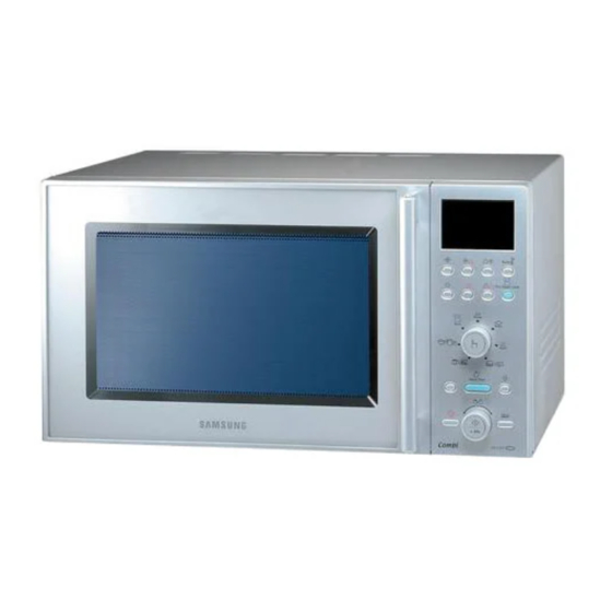
Page 3: Operating Instructions
3. Operating Instructions 3-1 Control Panel 3-2 Features & External Views Door Ventilation Holes Light Safety Interlock Holes Control Panel Guide Roller Glass Plate Door Latches Coupler Grill Rack 234mm 355mm 522mm 539mm... - Page 4 3. Operating Instructions 3-1 Control Panel 3-2 Features & External Views Door Ventilation Holes Light Safety Interlock Holes Control Panel Guide Roller Glass Plate Door Latches Coupler Grill Rack 234mm 355mm 522mm 539mm...
-
Page 5: Disassembly And Reassembly
4. Disassembly and Reassembly 4-1 Replacement of Magnetron, Motor Assembly and Lamp Remove the magnetron including the shield case, permanent magnet, choke coils and capacitors (all of which are contained in one assembly). 1. Disconnect all lead wires from the magnetron and lamp. -
Page 6: Replacement Of Door Assembly
4-3 Replacement of Door Assembly 4-3-1 Removal of Door Assembly Remove hex bolts securing the upper hinge and lower hinge. Then remove the door assembly. 4-3-2 Removal of Door "C" Insert flat screwdriver into the gap between Door "E" and Door "C" to remove Door "C". Be careful when handling Door "C"... -
Page 7: Replacement Of Fuse
4-3-5 Reassembly Test After replacement of defective component parts of the door, reassemble it and follow the instructions below for proper installation and adjustment so as to prevent an excessive microwave leakage. 1. When mounting the door to the oven, be sure to adjust the door parallel to the bottom line of the oven face plate by moving the upper hinge and lower hinge in the direction necessary for proper alignment. -
Page 8: Replacement Of Control Circuit Board
4-6 Replacement of Control Circuit Board 4-6-1 Removal of Control Box Assembly 1. Be sure to ground any static electric charge in your body and never touch the control circuit. 2. Disconnect the connectors from the control circuit board. 3. Remove screws securing the control box assembly. -
Page 9: Alignment And Adjustments
5. Alignment and Adjustments PRECAUTION 1. High voltage is present at the high voltage terminals during any cook cycle. 2. It is neither necessary nor advisable to attempt measurement of the high voltage. 3. Before touching any oven components or wiring, always unplug the oven from its power source and discharge the high voltage capacitor. -
Page 10: High Voltage Capacitor
5-4 High Voltage Capacitor 1. Check continuity of the capacitor with the meter set at the highest resistance scale. 2. Once the capacitor is charged, a normal capacitor shows continuity for a short time, and then indicates 9M . 3. A shorted capacitor will show continuous continuity. 4. -
Page 11: Output Power Of Magnetron
5-8 Output Power of Magnetron CAUTION MICROWAVE RADIATION PERSONNEL SHOULD NOT ALLOW EXPOSURE TO MICROWAVE RADIATION FROM MICROWAVE GENERATOR OR OTHER PARTS CONDUCTING MICROWAVE ENERGY. The output power of the magnetron can be measured by performing a water temperature rise test. Equipment needed : * Two 1-liter cylindrical borosilicate glass vessel (Outside diameter 190 mm) * One glass thermometer with mercury column... -
Page 12: Procedure For Measurement Of Microwave Energy Leakage
5-9 Procedure for Measurement of Microwave Energy Leakage 1) Pour 275±15cc of 20±5° C(68±9° F) water in a beaker which is graduated to 600cc, and place the beaker in the center of the oven. 2) Start to operate the oven and measure the leakage by using a microwave energy survey meter. -
Page 13: Troubleshooting
6. Troubleshooting PRECAUTION 1. CHECK GROUNDING BEFORE CHECKING FOR TROUBLE. 2. BE CAREFUL OF THE HIGH VOLTAGE CIRCUIT. 3. DISCHARGE THE HIGH VOLTAGE CAPACITOR. 4. WHEN CHECKING THE CONTINUITY OF THE SWITCHES OR TRANSFORMER, DISCONNECT ONE LEAD WIRE FROM THESE PARTS AND THEN CHECK CONTINUITY WITHOUT THE POWER SOURCE ON. - Page 14 6-1 Electrical Malfunction(continued) SYMPTOM CAUSE CORRECTIONS Oven lamp and fan motor turn on 1. Misadjustment or loose wiring Adjust door and latch switches. of primary latch switch 2. Defective primary latch switch Oven can program but timer 1. Open or loose wiring of does not start.
-
Page 15: Exploded Views And Parts List
7. Exploded Views and Parts List 7-1 Exploded Views X024 M002 X038 M003 M001 M016 X021 W003 M005 M013 X022 M058 M095 M113 M008 M010 M015 X004 M011 M053 M009 P024 W006 M012 W002 M019 M017 P129 W024 M023 M029 M054 H018 B018... -
Page 16: Main Parts List
CE1115/XEF,CONVECTIO W003 DE96-00296A ASSY-WIRE HARNESS-B CE1100/XEF,CONVECTIO W006 DE39-40409A WIRE HARNESS-E 230V50HZ,M9G45,CTW,-,-,- W024 DE96-00315A ASSY-WIRE HARNESS-SENSOR CE1150/XEF,CONV X004 DE99-00242J ASSY-CLEAN WATER BOWL CE1150R-S/BWT,SPS(LG SP2306FS) X021 DE70-00384A PLATE-STEAM C115,STS304,-,T0.5,-,-,-,-,- X022 DE75-00034A BOWL-STEAM C115,HEAT-RESISTING PP,-,-,-, X024 DE63-00189A COVER-STEAM BOWL C115,STS304,T0.5,-,-,-, X038 DE75-00037A RACK-STEAM... -
Page 17: Door Parts List
7-3 Door Parts List D009 D004 D010 D002 D049 D006 D024 D007 D026 D011 D019 Code No. Description Specification Q'ty Remark D002 DE64-00776A DOOR-A C115,PC LEXAN#141,WHT,1.1 CONV,-, D004 DE94-00428E ASSY DOOR-E 1.1 AQUA CONV,SEALANT,- D006 DE64-01043A DOOR-C CE1100,PBT,-,-,-,-,BLK,1.1 AQUA C D007 DE61-00193A SPRING-KEY... -
Page 18: Control Parts List
C001 DE94-00913C ASSY CONTROL-PANEL -,CE1150R/BWT,WHT,RUSSIA C001 DE94-00913D ASSY CONTROL-PANEL -,CE1150R-SL/BWT,SILVER,RUSSIA SILVER C003 RC-CE1150-01 ASSY PCB PARTS CE1151T/XEF,230V50HZ C005 DE64-00779C CONTROL-PANEL CE1150R/BWT,PC LEXAN#141,-,-,-,-,WHT, C005 DE64-00779J CONTROL-PANEL CE1150R-S/BWT,PC LEXAN#141,-,-,-,-,PURE-SILVER, SILVER C009 DE64-00780A WINDOW-DISPLAY C115,SAN(CR5381),SMG,1.1 C010 DE64-00789B BUTTON-SELECT CE1150,PC LEXAN#141,-,-,WH C010 DE64-00789D BUTTON-SELECT... -
Page 19: Casing Parts List
7-5 Casing Parts List H001 H002 H011 H013 H004 H012 H005 H002 H017 H010 H003 H007 H008 Code No. Description Specification Q'ty Remark H001 DE31-10171A MOTOR CONVECTION SMC-105EA,230V/50HZ,280 H002 DE31-90019A BLADE-FAN SECC,T0.6,-,-,-,-,- H002 DE31-90020A BLADE-FAN ALSTAR,T0.6,W250,L250,-,-,- H003 DE47-70077A HEATER-CONVECTION SHC-118E1,-,-,1680W,-, H004 DE61-50484A BRACKET-HEATER... -
Page 20: Standard Parts List
7-6 Standard Parts List Code No. Description Specification Q'ty Remark DE60-20063A BOLT-FLANGE M4,10,ZPC3,YEL,MSWR,-,-,-,- HING-L/U DE60-30016A NUT-FLANGE M4,MSWR10,-,-,-,-,-,-,- SENSOR DE60-30016B NUT-FLANGE M4,MSWR10,FEFN,-,-,-,-,-,- DE60-10082H SCREW-A -,-,-,-,2S-4X12,TOOTHED,-,-,-,- P-OUTER DE60-10018A SCREW-ASSY MACHINE -,WS,MSWR10,SN1,PH,M4X0.7P,-,8,-,- B-EARTH DE60-10098A SCREW-ASSY TAP TITE -,GLD,SWRCH18A,ZPC2,PH,TC,-,M4X8,WT,- M-DRIVE DE60-10045A SCREW-TAP PH -,-,FEFZY,-,PH,M3,-,L6,-,- DE60-10052A SCREW-TAP PH -,-,FEFZY,-,PH,M4,-,L8,-,-... - Page 21 8.P.C.B Diagrams 8-1 P.C.B Diagrams ( This Document can not be used without Samsung's authorization. ) -34V TMP87PM74F -34V 5V-1 DF06S SMW250-05V_WHT KIA7805AF MMSZ5232B 470uF 0.02nF DGND GF1G ZMM55CV1 3.9K 100nF XTL1 NC 5 38 P15 8MHz -34V 36 P13...
-
Page 22: Schematic Diagrams
9. Schematic Diagrams 9-1 Schematic Diagrams ( This Document can not be used without Samsung's authorization. ) MAGNETRON HIGH VOLTAGE DIODE TO CHASSIS HIGH VOLTAGE CAPACITOR H.V.FUSE SYMBOL COLOR BROWN BLACK BLUE HIGH VOLTAGE TRANSFORMER... - Page 23 3501-001068 RELAY-POWER 24VDC,523MW,16000MA,1FORMA,15MS,10MS 3501-001155 RELAY-MINIATURE 24VDC,200MW,3000MA,1FORMA,10MS,10MS RY1,RY2,RY3,RY6,RY8 3601-001126 FUSE-CARTRIDGE 250V,1.6A,FAST-ACTING,CERAMIC,5x20mm FUSE1 3708-000219 CONNECTOR-FPC/FFC/PIC 21P,1.25MM,STRAIGHT,SN,ZIF,-,SINGLE DE07-00060A VF DISPLAY HNM-17LS01,HNM-17LS01,90*40*9.0,1/18,ND17,NS16 DSP1 DE09-00361A IC MICOM TMP87CM74F-5BE0,CE1150R-SL/BWT,80PIN,+5V,8Mhz, DE30-20016A BUZZER CBE2220BA,STICK,-,-,-,-,-,-,- DE47-40024A HOLDER-FUSE FH-51H,7.5A,-,-,-,-,- FUSE1 DE61-00504A HOLDER-DIGITRON NEW-WAVE,PP,-,-,-,BLK,- DSP1 0401-001083 DIODE-SWITCHING MM4148,100V,150MA,LL-34,TP D05~D12,D14~21 0402-001080 DIODE-RECTIFIER GF1G,400V,1A,DO,TP...
Need help?
Do you have a question about the CE1150R and is the answer not in the manual?
Questions and answers