Table of Contents
Advertisement
ROCKY–3702EV Ver.4.x
Celeron
With VGA & Ethernet SBC
©Copyright 1999 by ICP Electronics Inc. All Rights Reserved. Manual first
edition Apr.01, 1999.
The information in this document is subject to change without prior notice
in order to improve reliability, design and function and does not represent
a commitment on the part of the manufacturer.
In no event will the manufacturer be liable for direct, indirect, special,
incidental, or consequential damages arising out of the use or inability to
use the product or documentation, even if advised of the possibility of
such damages.
This document contains proprietary information protected by copyright. All
rights are reserved. No part of this manual may be reproduced by any
mechanical, electronic, or other means in any form without prior written
permission of the manufacturer.
Trademarks
ROCKY-3702EV is a registered trademark of ICP Electronics Inc. IBM PC
is a registered trademark of International Business Machines Corporation.
Intel is a registered trademark of Intel Corporation. AMI is a registered
trademark of American Megatrends, Inc. Other product names mentioned
herein are used for identification purposes only and may be trademarks
and/or registered trademarks of their respective companies.
TM
& Pentium III Processor
Advertisement
Table of Contents

Subscribe to Our Youtube Channel
Related Manuals for ICP ROCKY–3702EV


Summary of Contents for ICP ROCKY–3702EV
- Page 1 Celeron & Pentium III Processor With VGA & Ethernet SBC ©Copyright 1999 by ICP Electronics Inc. All Rights Reserved. Manual first edition Apr.01, 1999. The information in this document is subject to change without prior notice in order to improve reliability, design and function and does not represent a commitment on the part of the manufacturer.
-
Page 3: Table Of Contents
Contents 1. Introduction ...............3 Specifications ................4 What You Have ................6 2. Installation.................7 ROCKY-3702EV's Layout ............8 Unpacking Precautions ..............9 Setting the CPU of ROCKY-3702EV .......... 10 Watch-Dog Timer ..............10 DiskOnChip™ Flash Disk ............11 Clear CMOS Setup ..............11 PS/2 Mouse................ - Page 4 4. AMI BIOS Setup..............20 Getting Start ................20 Standard CMOS Setup .............. 21 Advanced CMOS Setup ............. 22 Advanced Chipset Setup............24 Power Management Setup ............26 PCI/PLUG AND PLAY Setup............27 Peripheral Setup ................ 28 Hardware Monitor Setup ............30 Change Supervisor/User Password ..........
-
Page 5: Introduction
Introduction ® Welcome to the ROCKY-3702EV Socket 370 Celeron Pentium III ( FC-PGA ) with AGP VGA & 10/100Mbps Ethernet Single Board Computer. The ROCKY-3702EV is a PICMG bus ® form factor board. It is equipped with high performance Intel Celeron up to 500MHz and Pentium III ( FC-PGA ) 500MHz ( or above ) Processor and advanced high performance multi-mode I/O, designed for the system manufacturers, integrators, or... -
Page 6: Specifications
1.1 Specifications : • ® CPU : support Intel Celeron up to 500 MHz , Pentium III ( FC-PGA ) 500 MHz ( or Above ) Processor. • Bus : PICMG bus, meets PCI 2.1 standard • DMA channels : 7 •... - Page 7 • Built-in LM78 Hardware Monitoring System to monitor power supply voltage and fan speed status. • IrDA port : Support Serial Infrared(SIR) and Amplitude Shift Keyed IR(ASKIR) interface. • USB port : Support two USB ports for future expansion. • ISAPLUS : designed to enhance the ISA bus drive capability •...
-
Page 8: What You Have
1.2 What You Have In addition to this User's Manual , the ROCKY-3702EV package includes the following items: • ® ROCKY-3702EV Socket 370 Celeron & Pentium III with AGP VGA & 10/100Mbps Ethernet SBC • Printer Cable/RS232 Cable • FDD/HDD Cable •... -
Page 9: Installation
Installation This chapter describes how to install the ROCKY-3702EV. The layout of ROCKY-3702EV is shown on the next page and the Unpacking Precautions that you should be careful with are described on the following page. Also included is the jumpers and switches setting for this board’s configuration, such as: CPU type selection, system clock setting and Watchdog timer. -
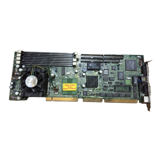
Page 10: Rocky-3702Ev's Layout
2.1 ROCKY-3702EV 's Layout ROCKY-3702EV Socket 370 Celeron & Pentium III with AGP VGA & 10/100Mbps Ethernet SBC... -
Page 11: Unpacking Precautions
2.2 Unpacking Precautions Some components on ROCKY-3702EV SBC are very sensitive to static electric charges and can be damaged by a sudden rush of power. To protect it from unintended damage, be sure to follow these precautions: ü Ground yourself to remove any static charge before touching your ROCKY-3702EV SBC. -
Page 12: Setting The Cpu Of Rocky-3702Ev
2.3 Setting the CPU of ROCKY-3702EV • JP3 : CPU FREQUENCY SETTING FREQUENCY 66MHz/100MHz Note: Intel Celeron CPU will auto-detect 66MHz Intel Pentium III ( FC-PGA ) CPU will auto-detect 100MHz • JP8 : CPU MULTIPLIER SETTING Ratio 3.0 x 3.5 x 4.0 x 4.5 x... -
Page 13: Diskonchip™ Flash Disk
• JP12 : WDT Time-out Period PERIOD 1 sec. 2 sec. 10 sec. 20 sec. 110 sec. 220 sec. 2.5 DiskOnChip™ Flash Disk The DiskOnChip™ (DOC) Flash Disk Chip is produced by M- Systems. Customers don‘t need any extra software utility because the DOC is 100% compatible to hard disk. -
Page 14: Ps/2 Mouse
2.7 PS/2 Mouse • JP7 : PS/2 Mouse Setting The PS/2 mouse uses IRQ12 while in operation . DESCRIPTION Enable the PS/2 Mouse, IRQ12 Disable the PS/2 Mouse ROCKY-3702EV Socket 370 Celeron & Pentium III with AGP VGA & 10/100Mbps Ethernet SBC... -
Page 15: Connection
Connection This chapter describes how to connect peripherals, switches and indicators to the ROCKY-3702EV board. 3.1 Floppy Disk Drive Connector ROCKY-3702EV board equipped with a 34-pin daisy-chain driver connector cable. • CN2 : FDD CONNECTOR PIN NO. DESCRIPTION PIN NO. DESCRIPTION GROUND REDUCE WRITE... -
Page 16: Pci E-Ide Disk Drive Connector
3.2 PCI E-IDE Disk Drive Connector You can attach four IDE (Integrated Device Electronics) hard disk drives to the ROCKY-3702EV IDE controller. CN1 (IDE 1) : Primary IDE Connector CN3 (IDE 2) : Secondary IDE Connector • CN1/CN3 : IDE Interface Connector PIN NO. -
Page 17: Parallel Port
3.3 Parallel Port This port is usually connected to a printer, The ROCKY-3702EV includes an on-board parallel port, accessed through a 26-pin flat- cable connector CN4. • CN4 : Parallel Port Connector PIN NO. DESCRIPTION PIN NO. DESCRIPTION STROBE# DATA 0 DATA 1 DATA 2 DATA 3... -
Page 18: Keyboard/Mouse Connector
• CN11 : Serial Port 2x5 pin header Connector (COMB) Pin No. Description Pin No. Description 3.5 Keyboard/Mouse Connector The ROCKY-3702EV provides one external keyboard ,one external mouse and one PS/2 keyboard & mouse connectors. • CN8 : 5-pin Header External Keyboard Connector PIN NO. -
Page 19: External Switches And Indicators
3.6 External Switches and Indicators There are several external switches and indicators for monitoring and controlling your CPU board. All the functions are in the CN7 connector. • CN7 : Multi Panel PIN NO. DESCRIPTION PIN NO. DESCRIPTION SPEAKER KEYLOCK RESET SW IDE LED ATX POWER CONTROL... -
Page 20: Irda Infrared Interface Port
3.8 IrDA Infrared Interface Port ROCKY-3702EV built-in IrDA port supports Serial Infrared (SIR) or Amplitude Shift Keyed IR (ASKIR) interface. If you want to use the IrDA port, you have to configure the SIR or ASKIR model in the BIOS’s Peripheral Setup’s COM2. Then the normal RS-232 COM2 will be disabled. -
Page 21: Lan Rj45 Connector
3.10 LAN RJ45 Connector ROCKY-3702EV is equipped with a built-in 10/100Mbps Ethernet Controller. You can connect it to your LAN through RJ45 LAN connector. The pin assignments are as following: • CN10 : LAN RJ45 Connector • CN5 : LED Connector for LAN LAN ACT. -
Page 22: Ami Bios Setup
AMI BIOS Setup The ROCKY-3702EV uses the AMI PCI/ISA BIOS for system configuration. The AMI BIOS setup program is designed to provide maximum flexibility in configuring the system by offering various options which selected end-user requirements. This chapter is written to assist you in the proper usage of these features. -
Page 23: Standard Cmos Setup
4.2 Standard CMOS Setup The standard CMOS Setup is used for basic hardware system configuration. The main function is for Date/Time setting and Floppy/Hard Disk setting. Please refer to the following screen for this setup To set the Date , for example, press either the arrow or <Enter> button on your keyboard to select one of the fields (Months, Date or Year) then press either <PgUp>... -
Page 24: Advanced Cmos Setup
4.3 Advanced CMOS Setup This Advanced CMOS Setup is designed for tuning the best performance of the ROCKY-3702EV board. As for normal operation customers don‘t have to change any default setting. The default setting is pre-set for most reliable operation. The following screen will be displayed if you select Advanced CMOS Setup: You can change the value of each options by using <PgUp>... - Page 25 Try Other Boot Devices > the BIOS will try to boot from any other available device in the system if the 1 and 3 device fails to boot. Floppy Access Control > to define the read/write access which is set when booting from a floppy drive. Hard Disk Access Control >...
-
Page 26: Advanced Chipset Setup
enable it then the BIOS will be executed from the RAM. Each option allows 16KB segment to be shadowed to the RAM. 4.4 Advanced Chipset Setup This setup functions are working mostly for Chipset (Intel 440BX). These options are used to change the Chipset‘s registers. - Page 27 DRAM Refresh Rate > to specify the timing for DRAM Refresh Memory Hole : to specify the location of a memory hole in the CMOS RAM. This setting reserve 15MB to 16MB memory address space for ISA expansion cards that specifically require this setting.
-
Page 28: Power Management Setup
4.5 Power Management Setup Power Management/APM > to enable or disable the Advanced Power Management feature. Green PC Monitor Power State > to specify the power state of the monitor after the specified period of display-idle has ended. Video Power Down Mode > to specify the power state of the VESA VGA video subsystem after the specified period of display- idle has ended. -
Page 29: Pci/Plug And Play Setup
4.6 PCI / PLUG AND PLAY Setup The setup help user handles the ROCKY-3702EV board‘s PCI function. All PCI bus slots on the system use INTA#, thus all installed PCI slots must be set. Plug and Play Aware O/S > Yes or No When PNP OS is installed, interrupts will be reassigned by the OS when the setting is Yes. -
Page 30: Peripheral Setup
Offboard PCI IDE Primary (/Secondary) IRQ > to specify the PCI interrupt that is assigned to the Primary (/Secondary) IDE channel on the offboard PCI IDE controller. PCI Slot (1,2,3,4) IRQ Priority > to specify the IRQ priority to be used by the PCI devices on slot 1 to 4. DMA Channel (0,1,3,5,6,7) >... - Page 31 Onboard Serial Port A (/B) > to specify the I/O port address of the serial port 1(/2). If you set it Auto, the BIOS will decide the correct I/O port address, automatically. Serial Port B Mode > to specify the mode of serial port 2. IR Duplex Mode >...
-
Page 32: Hardware Monitor Setup
4.8 Hardware Monitor Setup There is a LM78 chip on your board which can monitor on board system voltage and fan speed. The voltage monitoring will cover +5V,+12V,-12V,and –5V. Note: normal CPU Fan RPM is over than 5000 RPM. If your CPU Fan RPM is less than that figure, something is wrong and the CPU will be in overheat condition. -
Page 33: Change Supervisor/User Password
4.9 Change Supervisor / User Password This option sets a password that is used to protect your system and Setup Utility. Supervisor Password has higher priority than User Password. Once you setup the password, the system will always ask you to key-in password every time you enter the BIOS SETUP. -
Page 34: Auto-Detect Hard Disk
4.10 Auto-Detect Hard Disk This option detects the parameters of an IDE hard disk drive (HDD sector, cylinder, head, etc) automatically and will put the parameters into the Standard CMOS Setup screen. Up to 4 IDE drives can be detected and the parameters will be listed in the box. -
Page 35: Auto Configuration With Fail Save Settings
4.12 Auto Configuration with Fail Save Settings This option lets you load the Fail Safe default settings when something happens to your computer so that it cannot boot normally. These settings are not the most optimal settings but are the most stable settings. 4.13 Save Settings and Exit Select this option when you finish setting all the parameters and want to save them into the CMOS. -
Page 36: E 2 Key Function
Key™ Function The ROCKY-3702EV provides an outstanding E KEY™ function for system integrator. Based on the E KEY™, you can free to store the ID Code, Password or Critical Data in the 1Kbit EEPROM. Because the EEPROM is nonvolatile memory, you don’t have to worry for losing very important data. - Page 37 /* This function will write the given data to E KEY™ at certain address. The address range is from 0 to 63. The data value is from 0 to 0xffff. */ To easily start to use the function, please refer to the included EKEYDEMO.C code at first.
-
Page 38: Appendix A. Watch-Dog Timer
Appendix A. Watch-Dog Timer The WatchDog Timer is provided to ensure that standalone systems can always recover from catastrophic conditions that cause the CPU to crash. This condition may have occurred by external EMI or a software bug. When the CPU stops working correctly, hardware on the board will either perform a hardware reset (cold boot) or a Non-Maskable Interrupt (NMI) to bring the system back to a known state. -
Page 39: Appendix B. Atx Power Supply
Appendix B. ATX Power Supply The following notes show how to connect ATX Power Supply to the backplanes and / or the ISBC card. A. For backplanes with ATX Connector Please, disconnect the AC cord of the Power Supply from the AC source to prevent sudden electric surge to the board. - Page 40 2.2. Type B (through Power Button & GND) : PCISA-258EV, PCISA- 358SV (ROCKY-528AGP, ROCKY-528AGP-100). Please refer to this figure: The example shown on this figure is the connection with PCISA- 258EV. Connect the ATX power supply switch to the pin 18 (power button) and pin 20 (GND) of J1 on the board.
- Page 41 2.3. ROCKY-P258BX (through Power Button & +5VSB): Connect the ATX power supply switch to the pin 18 (power button) and pin 20 (+5VSB) of CN14 on the board. If you wish to turn off the power supply, please push the ATX power switch button for about 4 sec.
- Page 42 2.4. ROCKY-3702EV (through Power Button & +5VSB): Connect the ATX power supply switch to the pin 17 (power button) and pin 19 (+5VSB) of CN7 (multi panel) on the board. If you wish to turn off the power supply, please push the ATX power switch button for about 4 sec.
- Page 43 Connect the other port of the cable kit to the ATX power supply. Plug in the AC jack to the AC source, the unit is ready to switch ON now. To turn OFF the power supply, please push the ATX power switch button for about 5 sec.
- Page 44 C. For the backplanes with ATX power supply connector For some SBC without ATX power ON/OFF function, then you can control the ATX power supply through backplane’s PS ON connector. Refer to the figure below: for the backplanes with ATX connector, the connection can be made simply as following: Connect the ON/OFF (ordinary one) switch to Pin 2 (PS ON) and Pin 3 (GND) of connector CN2...
Need help?
Do you have a question about the ROCKY–3702EV and is the answer not in the manual?
Questions and answers