Table of Contents
Advertisement
ROCKY - 3782EVS/EV/V
Pentium® III, Celeron™, VIA C3® with
Dual Ethernet, VGA, Audio,
Dual Ultra-160 SCSI Port SBC
Ver 2.x
@Copyright 2000
All Rights Reserved.
Manual first edition July 14, 2000
The information in this document is subject to change without prior
notice in order to improve reliability, design and function and does not
represent a commitment on the part of the manufacturer.
In no event will the manufacturer be liable for direct, indirect, special,
incidental, or consequential damages arising out of the use or inability to
use the product or documentation, even if advised of the possibility of
such damages.
This document contains proprietary information protected by copyright.
All rights are reserved. No part of this manual may be reproduced by
any mechanical, electronic, or other means in any form without prior
written permission of the manufacturer.
Trademarks
ROCKY-3782EVS is registered trademarks of ICP Electronics Inc., IBM
PC is a registered trademark of International Business Machines
Corporation. Intel is a registered trademark of Intel Corporation.
AWARD
is
registered
trademarks
INTERNATIONAL, Inc. Other product names mentioned herein are
used for identification purposes only and may be trademarks and/or
registered trademarks of their respective companies.
1
of
AWARD
SOFTWARE
Contents
1. Introduction...........................................................5
1.1
Specifications ......................................................................................6
1.2
What You Have ...................................................................................7
2. Installation.............................................................8
2.1
ROCKY-3782EVS's Layout ...............................................................9
2.2
Clear CMOS Setup ...........................................................................10
2.3
BIOS Protection Setting................................................................... 10
2.4
CompactFlash Card Master/Slave Mode Setting...........................10
2.5
System Power On by Keyboard .......................................................11
2.6
SCSI A/B Terminator Selection Setting ..........................................11
3. Connection ......................................................... 12
3.1
Floppy Disk Drive Connector............................................................12
3.2
PCI E-IDE Disk Drive Connector......................................................13
3.3
Parallel Port .......................................................................................14
3.4
Serial Ports ........................................................................................14
3.5
Keyboard/Mouse Connector............................................................15
3.6
USB Port Connector.........................................................................16
3.7
External Switches and Indicators.....................................................16
2
Advertisement
Table of Contents

Subscribe to Our Youtube Channel
Related Manuals for ICP ROCKY-3782EVS


Summary of Contents for ICP ROCKY-3782EVS
-
Page 1: Table Of Contents
PCI E-IDE Disk Drive Connector............13 Trademarks Parallel Port ..................14 ROCKY-3782EVS is registered trademarks of ICP Electronics Inc., IBM PC is a registered trademark of International Business Machines Serial Ports ..................14 Corporation. Intel is a registered trademark of Intel Corporation. - Page 2 IrDA Infrared Interface Port ..............17 4.12 Frequency/Voltage Control ..............55 Fan Connector .................17 4.13 Defaults Menu ...................56 3.10 PS-ON Connector................18 4.14 Supervisor/User Password Setting ..........57 3.11 LAN RJ45 Connectors ..............18 4.15 Exit Selecting ..................58 3.12 VGA Connector ................18 Appendix A. WatchDog Timer ........ 59 3.13 Audio Connectors ................19 Appendix B.
-
Page 3: Introduction
The max memory is up to 512MB(SDRAM Speed is all the performance, reliability, and quality at a reasonable price. 100MHz Only). In addition, the ROCKY-3782EVS provides on chip VGA. The • Ultra ATA/33/66 IDE Interface : Two PCI Enhance IDE hard drives. -
Page 4: What You Have
IT8888F PCI To ISA Bridge • Mouse : PS/2 Mouse Port on-board. This chapter describes how to install the ROCKY-3782EVS. At • Power Consumption : 5V/5A (PIII 500, 64MDRAM, running 3D first, the layout of ROCKY-3782EVS is shown, and the WINMARK on WIN98) unpacking information that you should be careful is described. -
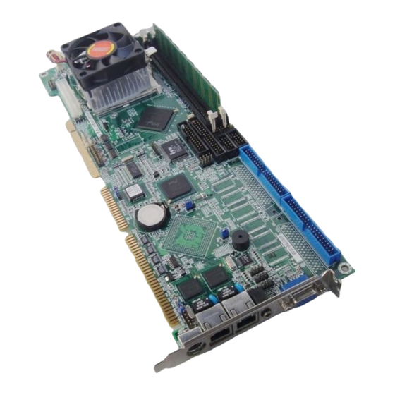
Page 5: Rocky-3782Evs's Layout
ROCKY-3782EVS's Layout 2.2 Clear CMOS Setup If want to clear the CMOS Setup(for example forgot the password you should clear the setup and then set the password again.),you should close the JP3(2-3) about 3 seconds, then open again. Set back to normal operation mode. -
Page 6: System Power On By Keyboard
This chapter describes how to connect peripherals, switches and indicators to the ROCKY-3782EVS board. 3 2 1 3.1 Floppy Disk Drive Connector DESCRIPTION ROCKY-3782EVS board is equipped with a 34-pin daisy-chain Disabled driver connector cable. Enabled • CN2 : FDC CONNECTOR 6 …... -
Page 7: Pci E-Ide Disk Drive Connector
You can attach four IDE( Integrated Device Electronics) hard disk drives to the ROCKY-3782EVS IDE controller. This port is usually connected to a printer, The ROCKY-3782EVS IDE2 shares the same IDE channel with CompactFlash, so you includes an on-board parallel port, accessed through a 26-pin flat-cable must refer JP10 before setting the IDE2’s device. -
Page 8: Keyboard/Mouse Connector
3.6 USB Port Connector • CN3/CN4 : Serial Port 10-pin Connector The ROCKY-3782EVS built in two USB(Spec. 1.1) ports for the PIN NO. DESCRIPTION future new I/O bus expansion. DATA CARRIER DETECT (DCD) CN9 : 2 ports USB Connector RECEIVE DATA... -
Page 9: Irda Infrared Interface Port
3.8 IrDA Infrared Interface Port 3.10 PS-ON Connector The ROCKY-3782EVS built in a IrDA port which supports Serial This connector is used to control the ATX power supply. Infrared(SIR) or Amplitude Shift Keyed IR(ASKIR) interface. • CN16 : PS-ON Connector When you use the IrDA port, you have to set COM2 as SIR or ASKIR mode in the BIOS’s Peripheral Setup. -
Page 10: External Led Connector
3.13 Audio Connectors 3.14 External LED Connector The onboard AC’97 Codec supports several audio functions. The LED connector includes SCSI active LED, Ethernet The audio connectors are described as below. Link/Active LED and Ethernet speed LED. CN12/CN13/CN14 Connector CN26 Connector 4 6 8 10 12 3 5 7 9 11... -
Page 11: Compactflash Storage Card Socket
3.15 CompactFlash Storage Card Socket 3.16 Ultra-160 68pin SCSI Connector Two 68pin SCSI connectors are described as below. The ROCKY-3782EVS configures CompactFlash Storage Card • CN19: Port A in IDE Mode(Used IDE 2). • CN20: Port B • CN24 : CompactFlash Storage Card Socket pin... - Page 12 3.17 ATX Connector 3.18 Smart Card Reader Connector The ROCKY-3782EVS offers one standard ATX power connector The Smart Card Reader connector pin define. CN21: CN27 Connector 20 18 16 14 12 10 8 6 4 2 14 13 19 17 15 13 11 9 7 5 3 1 •...
-
Page 13: Starting Setup
4.3 Using Setup In general, you can use the arrow keys to highlight items, press <Enter> to select, use the PageUp and PageDown keys to change entries, press BIOS Setup <F1> for help and press <Esc> to quit. The following table provides more details about how to navigate in the Setup program using the keyboard. -
Page 14: Main Menu
4.4.1 Setup Items 4.4 Main Menu The main menu includes the following main setup categories. Recall Once you enter the AwardBIOS™ CMOS Setup Utility, the Main Menu that some systems may not include all entries. will appear on the screen. The Main Menu allows you to select from several setup functions and two exit choices. -
Page 15: Standard Cmos Setup
This entry appears if your system supports PnP / PCI. See section 4.10 Exit Without Save for the details. Abandon all CMOS value changes and exit setup. See section 4.15 for the details. PC Health Status 4.5 Standard CMOS Setup Use this menu to monitor your hardware. - Page 16 Main Menu Selections IDE Adapters Item Options Description Date MM DD YYYY Set the system date. The IDE adapters control the hard disk drive. Use a separate sub menu Time HH : MM : SS Set the system time to configure each hard disk drive. Options are in its sub Press <Enter>...
- Page 17 Use the legend keys to navigate through this menu and exit to 4.6 Advanced BIOS Features the main menu. Use Table 3 to configure the hard disk. This section allows you to configure your system for basic operation. You have the opportunity to select the system’s default speed, boot-up Item Option Description...
- Page 18 Enabled Enable quick POST Disabled Normal POST Virus Warning First/Second/Third/Other Boot Device Allows you to choose the VIRUS Warning feature for IDE Hard Disk boot The BIOS attempts to load the operating system from the devices in the sector protection. If this function is enabled and someone attempt to sequence selected in these items.
- Page 19 Typematic Rate Setting OS Select For DRAM > 64MB Keystrokes repeat at a rate determined by the keyboard controller. Select the operating system that is running with greater than When enabled, the typematic rate and typematic delay can be selected. 64MB of RAM on the system.
- Page 20 DRAM Settings The first chipset settings deal with CPU access to dynamic random 4.7 Advanced Chipset Features access memory (DRAM). The default timings have been carefully chosen and should only be altered if data is being lost. Such a scenario might well occur if your system had mixed speed DRAM chips installed CMOS Setup Utility –...
- Page 21 The Choice: 2, 3. The Choice: Enabled,Disabled. System BIOS Cacheable Power-Supply Type Selecting Enabled allows caching of the system BIOS ROM at F0000h- This item controls the power-supply type to AT or ATX. FFFFFh, resulting in better system performance. However, if any program writes to this memory area, a system error may result.
-
Page 22: Integrated Peripherals
The integrated peripheral controller contains an IDE interface with two IDE channels. Select Enabled to activate each channel separately. The choice: Enabled, Disabled. 4.8 Integrated Peripherals IDE Primary/Secondary Master/Slave PIO CMOS Setup Utility – Copyright © 1984 – 2000 Award Software Integrated Peripherals The four IDE PIO (Programmed Input/Output) fields let you set a PIO On-Chip Primary PCI IDE... - Page 23 FDC or the system has no floppy drive, select Disabled in this field. to support AC97 Audio. The choice: Auto, Disabled. The choice: Enabled, Disabled. Onboard SCSI Device(ROCKY-3782EVS Only) Onboard Serial Port 1/Port 2 This item allows you to decide to enable/disable the onboard SCSI Device.
-
Page 24: Power Management Setup
This item allows you to enable/disable the Advanced Configuration and Watch-Dog Timer Unit Select Power Management (ACPI). Select the Watch-Dig Timer unit. The choice: Enabled, Disabled. The choice: Second, Minute ACPI Suspend Type 4.9 Power Management Setup The Power Management Setup allows you to configure you system to This item allows you to S1(Power ON Suspend)/S3(Suspend To RAM) most effectively save energy while operating in a manner consistent with the Advanced Configuration and Power Management (ACPI). - Page 25 When enabled and after the set time of system inactivity, all devices except the CPU will be shut off. The choice: 1Min, 2Min, 4Min, 8Min, 12Min, 20Min, 30Min, 40Min, 1Hour, Disabled. Video Off Method HDD Power Down This determines the manner in which the monitor is blanked. When enabled and after the set time of system inactivity, the hard disk drive will be powered down while all other devices remain active.
-
Page 26: Pnp/Pci Configuration Setup
a device which is configured as Enabled , even when the system is in a PnP OS Installed power down mode. Primary IDE 0 This item allows you to determine install PnP OS or not. Primary IDE 1 Secondary IDE 0 The choice: Yes, No. -
Page 27: Pc Health Status
the original PC AT bus specification, PCI/ISA PnP for devices compliant with the Plug and Play standard whether designed for PCI or ISA bus architecture. The Choice: PCI Device, Reserved. 4.11 PC Health Status DMA Resource When resources are controlled manually, assign each system DMA CMOS Setup Utility –... - Page 28 Spread Spectrum This item allows you to enable/disable the spread spectrum modulate. The choice: Enabled, Disabled. CPU Clock Ratio This item allows you to select CPU clock ratio. The choice: 3, 3.5, 4, 4.5, 5, 5.5, 6, 6.5, 7, 7.5, 8. 4.12 Frequency/Voltage Control 4.13 Defaults Menu CMOS Setup Utility –...
- Page 29 PASSWORD DISABLED. When a password has been enabled, you will be prompted to enter it every time you try to enter Setup. This prevents an unauthorized person from changing any part of your system configuration. Additionally, when a password is enabled, you can also require the BIOS to request a password every time your system is rebooted.
- Page 30 You have to call sub-function 2 to set the time-out period of Watchdog Timer first. If the time-out value is not zero, the Watchdog Timer will start counting down. While the timer value reaches zero, the system will reset. To ensure that this reset condition does not occur, the WatchDog Timer must be periodically refreshed by calling sub-function 2.
- Page 31 Appendix B. Address Mapping 1st MB Memory Address Map Memory address Description 00000-9FFFF System memory A0000-BFFFF VGA buffer IO Address Map C0000-C7FFF VGA BIOS C8000-CBFFF SCSI I/O address Range Description F0000-FFFFF System BIOS 000-01F DMA Controller #1 1000000- Extend BIOS 020-021 Interrupt Controller #1, Master *Default setting...
- Page 32 ATX power supply but has two types of power switch connection: connector 2.1. ROCKY-3782EVS (through Power Button & GND): For some SBC without ATX power ON/OFF function, then you can control the ATX power supply through backplane’s PS ON connector.
- Page 33 Appendix D. How to use Wake-Up Function The ROCKY-3782EVS provides two kind of Wake Up Function. This page describes how to use Modem Wake-Up and LAN Wake-Up function. Wake-Up function is working while you use ATX power supply, Wake-Up By Modem Ring On: You must set the option Power On By Ring of CMOS SETUP to be enabled.
Need help?
Do you have a question about the ROCKY-3782EVS and is the answer not in the manual?
Questions and answers