Table of Contents
Advertisement
Quick Links
ROCKY – 3703EVR
TM
Celeron
Pentium® III with
&
Dual LAN & ATA100 IDE RAID
Integrated S3 savage4 AGP4X VGA SBC
Ver 1.1
@Copyright 2001
All Rights Reserved.
Manual first edition MAR 30,2002
The information in this document is subject to change without prior notice in
order to improve reliability, design and function and does not represent a
commitment on the part of the manufacturer.
In no event will the manufacturer be liable for direct, indirect, special, incidental,
or consequential damages arising out of the use or inability to use the product or
documentation, even if advised of the possibility of such damages.
This document contains proprietary information protected by copyright. All rights
are reserved. No part of this manual may be reproduced by any mechanical,
electronic, or other means in any form without prior written permission of the
manufacturer.
Trademarks
ROCKY-3703EVR is registered trademarks of ICP Electronics Inc.; IBM PC is
a registered trademark of International Business Machines Corporation. Intel is a
registered trademark of Intel Corporation. AMI is registered trademarks of
American Megatrends Inc.. Other product names mentioned herein are used for
identification purposes only and may be trademarks and/or registered trademarks
of their respective companies.
Support
Any questions regarding the content of this manual or related issues can be e-
SUPPORT@IEI.COM.TW
mailed to us directly at:
Advertisement
Table of Contents

Subscribe to Our Youtube Channel
Related Manuals for ICP ROCKY 3703EVR


Summary of Contents for ICP ROCKY 3703EVR
- Page 1 Trademarks ROCKY-3703EVR is registered trademarks of ICP Electronics Inc.; IBM PC is a registered trademark of International Business Machines Corporation. Intel is a registered trademark of Intel Corporation. AMI is registered trademarks of American Megatrends Inc..
-
Page 2: Table Of Contents
Contents IrDA Infrared Interface Port .............19 CPU & SYSTEM Fan Connector............19 3.10 LAN RJ45 & STATE LED Connector ...........19 1. Introduction ..............4 3.11 VGA Connector ................19 Specifications ..................5 3.12 ATA-100 IDE RATD & Active LED Connector ......20 What You Have...................7 3.13 AUDIO Headphone &... -
Page 3: Introduction
Specifications Intel Celeron® and Pentium® III (FC-PGA) CPU(PGA370) Processor, supports 66/100/133 MHz FSB Bus interface PCI/ISA bus, PICMG compliant Introduction Bus speed ISA : 8MHz, PCI: 33MHz DMA channels Welcome to the ROCKY-3703EVR Celeron & Pentium® III Single Board Computer. The ROCKY-3703EVR board is an Interrupt levels ISA/PCI form factor board, which comes equipped with high performance Pentium®... -
Page 4: What You Have
What You Have Supports Serial Infrared(SIR) and Amplitude Shift IrDA port Keyed IR(ASKIR) interface In addition to this User's Manual, the ROCKY-3703EVR package includes the following items: USB port Supports Four USB ports for future expansion • One ROCKY-3703EVR Single Board Computer Software Programmable Reset or NMI is •... -
Page 5: Installation
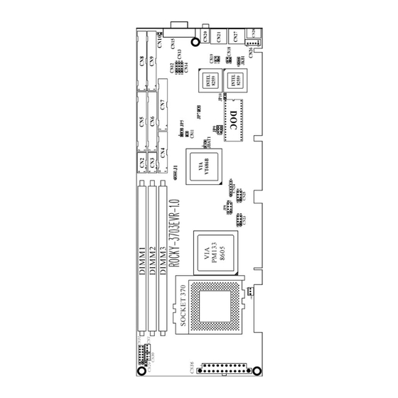
ROCKY – 3703EVR's Layout Installation This chapter describes how to install the ROCKY-3703EVR. At first, the layout of ROCKY-3703EVR is shown, and the unpacking information that you should be careful is described. The jumpers and switches setting for the ROCKY-3703EVR's configuration, such as CPU clock setting, and watchdog timer, are also included. -
Page 6: Unpacking Precautions
Unpacking Precautions Setting the CPU of ROCKY-3703EVR Some components on ROCKY-3703EVR SBC are very • JP8 : CPU Multiplier Setting sensitive to static electric charges and can be damaged by a sudden rush of power. To protect it from unintended damage, Speed be sure to follow these precautions: CLOSE... -
Page 7: Diskonchip™ Flash Disk
DiskOnChip™ Flash Disk (JP9) The DiskOnChip™ Flash Disk Chip(DOC) is produced by M- Systems. Because the DOC is 100% software compatible to hard disk and DOS, users don‘t need any extra software utility. It is just “plug and play” easy and reliable. At present the DOC is Connection available from 2MB to 144MB. -
Page 8: Floppy Disk Drive Connector
Floppy Disk Drive Connector (CN7) PCI E-IDE Disk Drive Connector (CN5, CN6) The ROCKY-3703EVR board is equipped with a 34-pin daisy- You can attach four IDE( Integrated Device Electronics) hard disk drives on two channels. These connectors support Ultra- chain drive connector cable. DMA100 IDE devices. -
Page 9: Parallel Port
Parallel Port (CN4) • Serial Port 10-pin Connector This port is usually connected to a printer. The ROCKY- PIN NO. DESCRIPTION 3703EVR includes an on-board parallel port, accessed through DATA CARRIER DETECT (DCD) a 26-pin flat-cable connector CN4. RECEIVE DATA (RXD) TRANSMIT DATA (TXD) -
Page 10: External Switches And Indicators
External Switches and Indicators (CN31) USB Port Connector (CN23, CN25) There are several external switches and indicators for The ROCKY- 3703EVR provide four built-in USB ports for the monitoring and controlling your CPU board. All the functions are future new I/O bus expansion. in the CN31 connector. -
Page 11: Lan Rj45 & State Led Connector
3.10 LAN RJ45 & State LED Connector (CN21,CN27) The ROCKY-3703EVR is equipped with two built-in 10/100Mbps • CN8(Channel 1)/CN9(Channel 2) : ATA-100 IDE RAID Ethernet controllers. You can connect it to your LAN through Connector, 40-pin RJ45 LAN connectors. There are two LED on the connector PIN NO. -
Page 12: Atx 20-Pin Power Connector
3.14 ATX 20-PIN Power Connector (CN16) This connector supports the ATX power, functions such as modem Ring on, wake-up LAN and soft power off are supported by mainboard. (Power source from Mainboard) AMI BIOS Setup PIN NO. DESCRIPTION PIN NO. DESCRIPTION 3.3V 3.3V... -
Page 13: Standard Cmos Setup
When choose Auto Configuration with Fail Safe Settings will load minimized settings Troubleshooting. For IDE hard disk drive setup, please check the following performance should be very poor when use this setting. possible setup procedure, When choose Auto Configuration with Optimal Settings will 1. -
Page 14: Advanced Chipset Setup
S.M.A.R.T. for Hard Disks > to allow BIOS to use the System Management and Reporting Technologies protocol for reporting server system information on a network BootUp Num-Lock > to turn on/off the Num-Lock option on an enhanced keyboard when you boot. If you turn it off, the arrow keys on the numeric keypad can be used just as the other set of arrow keys on the keyboard and vice versa. -
Page 15: Power Management Setup
Please carefully change any default setting, otherwise the AGP Aperture Size > to define the size of Graphics Aperture. system may become unstable. AGP Master 1 W/S Write>System will run single wait state delay before write data from buffer, if user set to "Disable" system will run twice wait states, so system can stable AGP Master 1 W/S Read>... -
Page 16: Peripheral Setup
Video Power Down Mode > to specify the power state of the VESA VGA video subsystem after the specified period of display-idle has ended. Hard Disk Power Down Mode > to specify the power state of the hard disk after the specified period of hard drive-idle has ended. -
Page 17: Pci /Plug And Play Setup
ECP (supports devices that comply with the Extended Capabilities Port). Parallel Port IRQ > to assign certain IRQ to the parallel port. The optimal and fail-safe settings are 7. Parallel Port DMA Channel > available only if the parallel port mode is ECP. -
Page 18: Hardware Monitor Setup
Hardware Monitor Setup Plug and Play Aware O/S > Yes or No This setup helps users monitor the ROCKY-3703EVR boards on board system voltage and fan speed. The function is When PnP OS is installed, the OS will reassign interrupts when implemented by on board VIA686 chip. -
Page 19: Appendix A. Watch-Dog Timer
Example assembly program: TIMER_PORT = 443H TIMER_START = 443H Appendix A. Watch-Dog Timer TIMER_STOP = 843H The WatchDog Timer is a device to ensure that standalone systems can ;;INITIAL TIMER COUNTER always recover from abnormal conditions that cause the system to crash. -
Page 20: Appendix B. I/O Address Map
Appendix B. I/O Address Map 1 st MB Memory Address Map • I/O Address Map Memory address Description I/O Address Description 00000-9FFFF SYSTEM MEMORY A0000-BFFFF VGA BUFFER 000-01F DMA Controller #1 C0000-C7FFF VGA BIOS 020-021 Interrupt Controller # 1, Master C8000-CFFFF NO USE 040-05F... -
Page 21: Appendix C. Atx Power Supply
Appendix C. ATX Power Supply The following notes show how to connect ATX Power Supply to the backplanes and / or the ISBC card. A. For backplanes with ATX Connector Please, disconnect the AC cord of the Power Supply from the AC source to prevent sudden electric surge to the board. -
Page 22: Appendix D. How To Used Wake Up Function
Appendix D. How to use Wake-Up Function Appendix E. RAID FastTrak100 1. Introduction The ROCKY-3703EVR provides two kind of Wake up Function. This page describes how to use Modem Wake-Up and LAN Wake-Up function. Promise designed its FastTrak100 to provide a cost-effective, high Wake-Up function is working while you use ATX power supply, performance RAID that adds performance and/or reliability to PC desktops and/or servers using Ultra ATA/100, Ultra ATA/66, or EIDE... - Page 23 FastTrak100's bootable BIOS supports individual drives larger than 8.4GB. With FAT32 and NTFS partitioning, the array can press “Enter” key. 5. Choose “Win2000 Promise FastTrak100 Controller” from the be addressed as one large single volume. The FastTrak100 controller provides two IDE hard drive list that appears on screen, and then press the “Enter”...
- Page 24 Computer” followed by the System icon. running. If you’re installing the FastTrak100 drivers on a system 2. Choose the “Hardware” tab, and then click the “Device during an installation of Millenium, see “Installing Drivers During Manager” tab. Millenium Installation.” 3. Click the “+” in front of “SCSI controllers.” “Promise 1.
- Page 25 2. Install Windows 98 normally. 7. Click on “Next.” A message informing you that Windows has 3. After installation, go the “Start” menu and choose “Settings.” found “Win95-98 Promise FASTTRAK100 (tm) IDE Controller” 4. From the “Settings” menu, choose “Control Panel.” should appear.
- Page 26 3. FastTrack100 BIOS Utility The list will include “Win2000 Promise FastTrak100 (tm) controller”. NOTE: If you need to specify any additional devices to be in- stalled, do so at this time. Once all devices are specified, Creating Your Disk Array continue to step 6.
- Page 27 Creating an Array for Performance NOTE: FastTrak100 allows users to create striped arrays with 1, 2, 3, or 4 drives. To create an array for best performance, follow these steps: FastBuild (tm) Utility 1.xx (c) 1995-2000 Promise Technology, Inc. 1. Using the Spacebar, choose “Performance” under the Optimize [Auto Setup Options Menu] Array for section.
- Page 28 Creating a Security Array with an Existing Data Drive NOTE: FastTrak100 permits only two drives to be used for a single 4. Press “N” for the Create Only option. Mirrored array in Auto Setup. If more drives are physically attached to 5.
- Page 29 3. Press “Y” for the Create and Duplicate option. The window below 4. Using FastBuild™ Configuration Utility will appear asking you to select the Source drive to use. FastBuild will copy all data from the Source drive to the Target drive. The FastBuild Configuration Utility offers several menu choices to create and manage the drive array on the Promise FastTrak100 adapter.
- Page 30 Functional - The array is operational. Critical - A mirrored array contains a drive that has failed or Using the Main Menu disconnected. The remaining drive member in the array is functional. This is the first option screen when entering the FastBuild TM However, the array has temporarily lost its ability to provide fault Setup.
- Page 31 Creating Arrays Automatically page 68. The Auto Setup <1> selection from the Main Menu can To delete an array (but not delete the data contained on the array), intuitively help create your disk array. It will assign all available select “Deleting An Array” on page 77. drives appropriate for the disk array you are creating.
- Page 32 Defining Typical Application Usage attached in Auto Setup mode. Allows the user to choose the type of PC usage that will be performed in Security (RAID 1 Mirroring, or RAID 0+1 Striping/Mirroring) order to optimize how FastTrak100 handles data blocks to enhance Creates a mirrored (or fault tolerant) array for data security.
- Page 33 Viewing Drive Assignments Manually Creating an Array The View Drive Assignments <2> option in the Main Menu The Define Array <3> option from the Main Menu allows users displays whether drives are assigned to a disk arrays or are to begin the process of manually defining the drive elements unassigned.
- Page 34 Selecting Array Type Assigning Drive(s) to Array Under the Definition section of this menu, highlight the Array # for which 1. Under the [ Drive Assignments ] section, highlight a drive using the you want to assign a RAID level. [↑] Up [↓] keys.
- Page 35 1. After assigning the drives to a Mirroring array, press <Ctrl-Y> keys to Adding Fault Tolerance to an Existing Drive save your selection. The window below will appear. FastTrak100 will create a mirrored array using an existing Do you want the disk image to be duplicated to another? system drive with data.
- Page 36 Making a FastTrak100 Disk Array Bootable 6. Once “Y” is selected, the following progress screen will appear. The process will take a few minutes. WARNING: In order for you to boot from an array on the Please Wait While Duplicating The Image 10% Complete FastTrak100, your PC or server must be configured in the CMOS Setup to use the FastTrak100 as a bootable device...
- Page 37 Creating a “Hot” Spare Drive for Mirrored Arrays Deleting An Array The Delete Array <4> Menu option allows for deletion of disk array For automatic rebuilds of a mirrored array, attach an extra assignments. This is not the same as deleting data from the drives “spare”...
- Page 38 Array No RAID Mode Total Drv Capacity(MB) Status Rebuilding A Mirrored Array Array 1 Stripe 16126 Functional The Rebuild Array <5> Menu option is necessary to recover from an Stripe Block: 64 KB [ Drive Assignments ] error in a mirrored disk array. You will receive an error message when booting your system from the FastTrak BIOS.
- Page 39 Viewing Controller Settings [↑] Up [↓] Down [ESC] Exit [Enter] Select The Controller Configuration <6> menu selection allows you to enable 9. Highlight the array whose Status is “Critical”. or disable the FastTrak100 BIOS from halting (the default) if it detects an 10.
Need help?
Do you have a question about the ROCKY 3703EVR and is the answer not in the manual?
Questions and answers