Table of Contents
Advertisement
Quick Links
.........................................................................................................................
Leading Edge Dimmer/HF Ballast Controller Installation Manual
Warning..................................................... 2
Features..................................................... 2
Important Safeguards................................... 2
Internal View............................................... 3
Mounting.................................................... 4
Supply & Load Cable Connections................... 5
Connecting Serial Control Cables.................... 6
Hardware Controls .......................................7
.........................................................................................................................
WMGD Pty Limited trading as Dynalite
Unit 6, 691 Gardeners Road Mascot NSW 2020 Australia
t
f +61 2 8338 9333
+61 8338 9899
info@dynalite.com
contents
Dimmable Lamps Chart................................. 7
Hold Down Programming Of Presets................ 9
One Touch Button Operation.......................... 9
Troubleshooting........................................... 10
Specification.............................................. 10
Useful DyNet Op Codes............................... 11-12
ABN 33 097 246 921
dynalite-online.com
Advertisement
Table of Contents

Subscribe to Our Youtube Channel
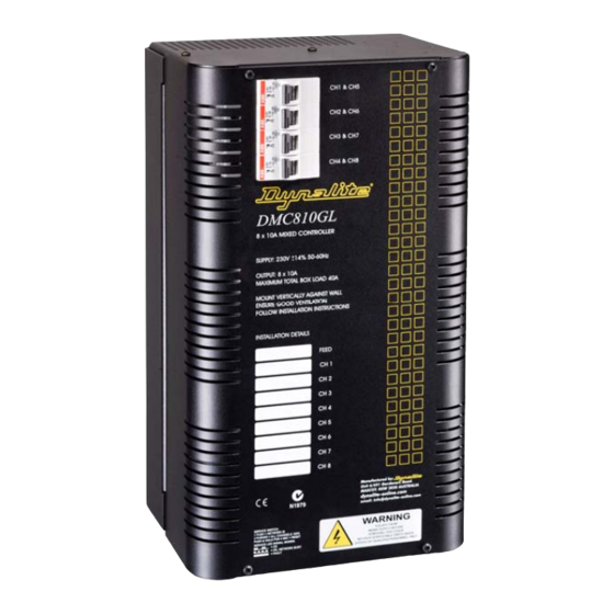
Summary of Contents for Dynalite DMC810GL
-
Page 1: Table Of Contents
Supply & Load Cable Connections.……………… 5 Specification………………………………………. 10 Connecting Serial Control Cables……………….. 6 Useful DyNet Op Codes…………………………. 11-12 Hardware Controls …………………………………7 ………………………………………………………………………………………………………..WMGD Pty Limited trading as Dynalite Unit 6, 691 Gardeners Road Mascot NSW 2020 Australia ... -
Page 2: Dmc810Gl
300mm – subject to local wiring regulations. If anticipated cable runs are over 600 metres for serial cables, consult your dealer for advice. Do not cut or terminate live data cables. ………………………………………………………………………………………………………..DMC810GL Instruction Manual Rev B.DOC... -
Page 3: Internal View
1-10V or DSI Control Outputs Earth Link Accessory Port DyNet Port Network Socket Service LED Low Voltage Cable Service Switch Gland For spare parts, please call your nearest Dynalite Customer Service Centre, and specify: DMC810GL ………………………………………………………………………………………………………..DMC810GL Instruction Manual Rev B.DOC... -
Page 4: Mounting
To ensure the cooling system functions correctly, the DMC810GL should only be mounted vertically, the right way up. The DMC810GL will generate heat when operating, approximately 2 Watts per Amp of load connected to the dimmed channels only, and requires an air gap of 200mm on each side and at the top and bottom of the device. -
Page 5: Supply & Load Cable Connections
100% output. there is no output on any or all channels, see the “Troubleshooting” section (page 11). This device shall be de-energised before terminating any control or data cables. ………………………………………………………………………………………………………..DMC810GL Instruction Manual Rev B.DOC... -
Page 6: Connecting Serial Control Cables
Do not cut or terminate live data cables. If the data cable has to cross over any mains cables, it is recommended that it do so at a 90 angle to minimise noise coupling. Sufficient insulation shall provided, subject local regulations. ………………………………………………………………………………………………………..DMC810GL Instruction Manual Rev B.DOC... -
Page 7: Hardware Controls
………………………………………………………………………………………………………..INCANDESCENT Incandescent lamps are easily dimmed using all Dynalite controllers. The soft start and voltage limit features will extend lamp life. Lamp life can be further extended using the LAMPS voltage limit adjustment. -
Page 8: Preset Programming Using The Program Key
STEP 6: When all channels of the preset scene have been established, press PROGRAM again and the levels will be stored to the current preset. To program another preset, repeat steps 1 - 6. ………………………………………………………………………………………………………..DMC810GL Instruction Manual Rev B.DOC... -
Page 9: Hold Down Programming Of Presets
To alternate between up and down stop pushing for a moment and then hold down again. The level that is selected is saved and restored when the lights off and then on again. ………………………………………………………………………………………………………..DMC810GL Instruction Manual Rev B.DOC... -
Page 10: Troubleshooting
………………………………………………………………………………………………………..Check the following list. If you are still unable to rectify the situation, contact your nearest Dynalite office. A complete list of distributors worldwide can be found on the Internet at: http://dynalite-online.com/html/contacts.htm. Please ensure that you have completed the following prior to calling our technical support department. -
Page 11: Useful Dynet Op Codes
Unused(usually 0) Example: Restore Saved Preset in Area 1: Byte 3 18 hex [1C] [01] [FA] [67] [00] [00] [FF] [83] Byte 4 Unused(usually 0) Byte 5 Unused(usually 0) Byte 6 Join (usually FF hex) ………………………………………………………………………………………………………..DMC810GL Instruction Manual Rev B.DOC... - Page 12 Example: Toggle Channel State of Area 4 CH8: [1C] [07] [09] [70] [00] [00] [FF] [65] Program Toggle Preset (sent to dimmer) Byte 0 1C hex Byte 1 AREA Byte 2 Channel Number (0 origin) Byte 3 7D hex ………………………………………………………………………………………………………..DMC810GL Instruction Manual Rev B.DOC...


Need help?
Do you have a question about the DMC810GL and is the answer not in the manual?
Questions and answers