Table of Contents
Advertisement
Quick Links
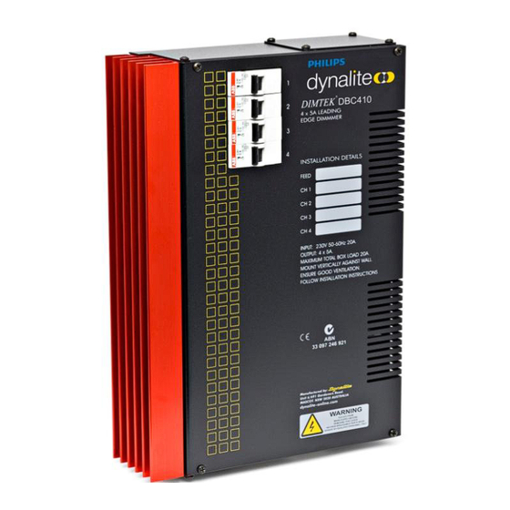
DBC410
4 x 10A HF Ballast Controller
Installation Manual
Warning..................................................... 2
Features..................................................... 2
Important Safeguards...................................
Internal View............................................... 3
Mounting.................................................... 4
Supply & Load Cable Connections...................
Connecting Serial Control Cables....................
Supplied by:
contents
Hardware Controls.............................................7
Troubleshooting................................................ 8
2
Speci cation..................................................... 8
5
6
Advertisement
Table of Contents

Related Manuals for Dynalite DBC410


Summary of Contents for Dynalite DBC410
-
Page 1: Table Of Contents
DBC410 4 x 10A HF Ballast Controller Installation Manual contents Warning…………………………………………….. 2 Hardware Controls.……………………………………..7 Features…………………………………………….. 2 Troubleshooting………………………………………… 8 Speci cation..…………………………………………… 8 Important Safeguards…………………………….. Internal View……………………………………….. 3 Mounting…………………………………….……… 4 Supply & Load Cable Connections.……………… Connecting Serial Control Cables……………….. Supplied by:... -
Page 2: Warning
A INSTALLATION, PROGRAMMING AND new Dynalite panel will turn on all lighting channels from MAINTENANCE MUST BE CARRIED OUT BY button 1 and turn off from button 4 if network terminations QUALIFIED PERSONNEL. -
Page 3: Internal View
LINE 3 LINE 4 Transformer DyNet Network Connections Control CPU Knock Out For Low Voltage Cable Network Socket Service Switch Depth 75mm For spare parts, please call your nearest Dynalite Customer Service Centre, and specify DBC410 DBC410 Installation Manual Rev K.docx... -
Page 4: Mounting
The DBC410 should be mounted vertically, the right way up. The DBC410 requires an air gap of 100mm on each side and at the top and bottom of the device. This air gap is... -
Page 5: Supply & Load Cable Connections
100% output. If there is no output on any or all channels, see the Troubleshooting section (page 8). device should be de energised before terminating the control and data cables. DBC410 Installation Manual Rev K.docx... -
Page 6: Connecting Serial Control Cables
30mm. A data cable that is connected to an energised dimmer is live. Do not cut or terminate live data cables. If the data cable has to cross over any mains cables, it should do so at a 90° angle. DBC410 Installation Manual Rev K.docx... -
Page 7: Hardware Controls
Accessory Module Socket - Accepts plug in modules for optional features such as DMX512 ports and Time clocks. Consult your distributor for details on the available accessory modules. DBC410 Installation Manual Rev K.docx... -
Page 8: Troubleshooting
DBC410 Installation Manual Rev K.doc Specifications and design subject to change without notice. Dynalite Manufactured by WMGD Pty Ltd (ABN 33 097 246 921). All rights reserved. Dynalite, Dimtek, DyNet and DLight and associated logos are the registered trademarks of Dynalite Intelligent Light Pty Ltd. Not to be reproduced without permission.
Need help?
Do you have a question about the DBC410 and is the answer not in the manual?
Questions and answers