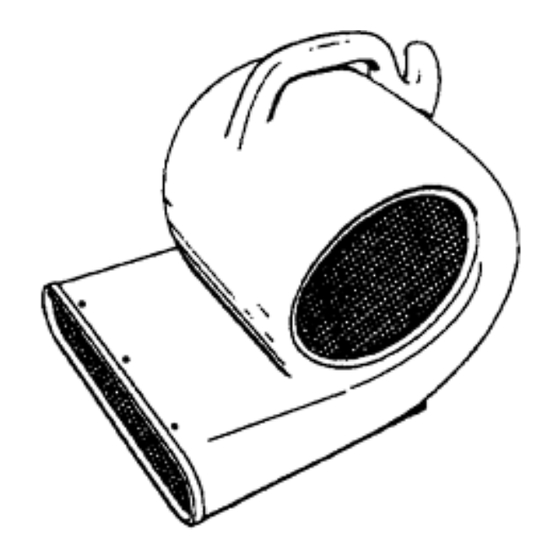
Summary of Contents for Windsor WB3
- Page 1 Operating Instructions (ENG) MODEL: WB3 Read instructions before operating the machine. WB3 98281 03/21/00...
-
Page 2: Machine Data Log/Overview
SALES REPRESENTATIVE # _____________________ DEALER NAME ________________________________ OPERATIONS GUIDE NUMBER ___________________ PUBLISHED __________________________________________ Copyright 1995 Windsor Industries, Printed in USA YOUR DEALER Name: __________________________________________________________________________________________________ Address: _______________________________________________________________________________________________ For the name and address of your dealer contact: Windsor Industries Phone Number: _________________________________________________________________________________________ WB3 98281 12/15/99... -
Page 3: How To Use This Manual
DESCRIPTION – column is a brief description of the part. Parts may be ordered from authorized Windsor SERIAL NO. FROM – column indicates dealers. When placing an order for parts, the the first machine the part number is machine model and machine serial number are applicable to. -
Page 4: Table Of Contents
Lubricating Motor Sleeve Bearings... …8 Fan Removal..........…8 Power Cord/Capacitor....... …8 Motor Removal......... …8 Switch Replacement…......…8 Wiring Diagram… ........…9 GROUP PARTS LIST Switch/Motor Assemblies ......…10 WB3 Assembly......... …12 Suggested Spare Parts/Notes....…14 Warranty........... …15 WB3 98281 12/15/99... -
Page 5: Important Safety Instructions
Do not pull/run machine over cord. Keep cord away from heated surfaces. Connect to a properly grounded outlet. See Grounding Instructions. Use only on GFCI protected receptacles. Do not use this fan with any solid-state speed control device. SAVE THESE INSTRUCTIONS WB3 98281 12/15/99... -
Page 6: Hazard Intensity Level
Unless Operation Guide is Read and understood. In Flammable or Explosive areas. In areas with possible falling objects. WHEN SERVICING MACHINE: Avoid moving parts. Do not wear loose clothing; jackets, shirts, or sleeves when working on the machine. Use Windsor approved replacement parts. WB3 98281 12/15/99... -
Page 7: Grounding Instructions
The green colored rigid ear, lug, or wire extending from the adaptor must be connected to a permanent ground such as a properly grounded outlet box cover. Whenever the adaptor is used, it must be held in place by a metal screw. WB3 98281 03/21/00... -
Page 8: Operation
3. Loosen setscrew on fan hub and remove fan from motor shaft. NOTE: When reinstalling the fan, make sure the motor shaft is clean and apply a thin coat of silicon lubricant to shaft to help assembly. WB3 98281 12/15/99... -
Page 9: Wiring Diagram
WIRING DIAGRAM 115V Wiring Diagram: NOTE: 240V uses blue & brown vs. white & black, respectively. WB3 98281 12/15/99... -
Page 10: Switch/Motor Assemblies
SWITCH/MOTOR ASSEMBLIES Early Version of WB3 Switch Early Version of WB3 Motor A. Brkt, Motor Mounting (14299) B. Scr, 1/4-20 x 1" HHMS (70018) C. Nut, 1/4-20 Lock (57047) A. Knob (48029) B. Nut, Panel (57017) C. Plate, Switch (62215) D. - Page 11 NUT, 15/32-32 HEX PANEL ZINC 57187 NUT, 6-32 ACORN ZINC 87138 WASHER, #6 INT STAR ZINC 62333 PLATE, (GE) SWITCH 70448 SCR, 6-32 X ½ PFHMS PLTD 88315 WIRE, 5” GRN/18 76008 X 76030 72120 SWITCH, 3 SPEED ROTARY WB3 98281 12/15/99...
-
Page 12: Wb3 Assembly
WB3 ASSEMBLY WB3 98281 12/15/99... - Page 13 WB3 PARTS LIST SERIAL NO. PART NO. DESCRIPTION NOTES: FROM 23575 CORD ASM, 16/3 X 25 SJTW YLW WB3 73195 STRAIN RELIEF, ½ NPT 70066 SCR, 10-32 X ¾ PPHMS 70243 SCR, 8-32 X ½ SPHMS BLK 70386 SCR, 10-32 X 1.0 PPHMS...
-
Page 14: Suggested Spare Parts/Notes
SUGGESTED SPARE PARTS LIST/NOTES SUGGESTED SPARE PARTS LIST SERIAL NO. PART NO. DESCRIPTION NOTES: FROM 72120 SWITCH, 3 SPEED ROTARY 27272 CAPACITOR, 15 MFD 370V 50/60HZ 09023 BEARING ASM, SHAFT SUPPORT NOTES WB3 98281 12/15/99... -
Page 15: Warranty
If proof of purchase cannot be identified, the warranty start date is 90 days after date of sale to an authorized Windsor distributor. Parts replaced or repaired under warranty are guaranteed for the remainder of the original warranty period.


Need help?
Do you have a question about the WB3 and is the answer not in the manual?
Questions and answers