
Subscribe to Our Youtube Channel
Related Manuals for Windsor TRACER FS QTFSD


Summary of Contents for Windsor TRACER FS QTFSD
- Page 1 FLOOR SWEEPER Operating Instructions MODEL: TRACER FS QTFSD (Diesel Version) QTFSG (Gas Version) IPX4 Read these instructions before using the machine 98349 11/01/03...
-
Page 2: Machine Data Log
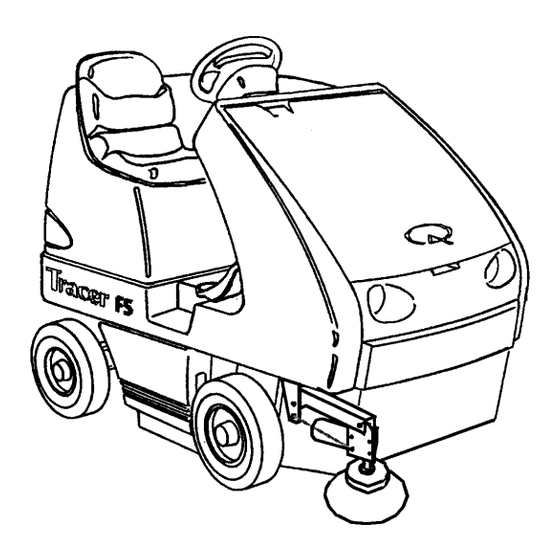
SERIAL NUMBER ______________________________ SALES REPRESENTATIVE # _____________________ DEALER NAME ________________________________ OPERATIONS GUIDE NUMBER ___________________ PUBLISHED __________________________________________ Copyright 1995 Windsor Industries, Printed in USA YOUR DEALER Name: __________________________________________________________________________________________________ Address: _______________________________________________________________________________________________ Phone Number: _________________________________________________________________________________________ OVERVIEW The Tracer Floor Sweeper is a gas or diesel powered, ride-on floor sweeper intended for industrial use. -
Page 3: Table Of Contents
TABLE OF CONTENTS Machine Data Log..........2 GROUP PARTS LIST Table of Contents ...........3 Frame Group..........5-1 HOW TO USE THIS MANUAL Differential Group ......... 5-3 Front Wheel Drive Group......5-5 How to use this Manual........1-1 Impeller Group..........5-7 Impeller (Wet Sweep Bypass) ..... 5-9 SAFETY Rear Clip Group. -
Page 4: How To Use This Manual
Belts correct repair parts. Differential Drive Skirts Parts may be ordered from authorized Windsor Hopper dealers. When placing an order for parts, the Brakes/Tires machine model and machine serial number are Battery Information important. -
Page 5: Important Safety Instructions
IMPORTANT SAFETY INSTRUCTIONS When using a gas or diesel powered appliance, basic precaution must always be followed, including the following: READ ALL INSTRUCTIONS BEFORE USING THIS MACHINE. WARNING: To reduce the risk of fire, electric shock, or injury: This machine is for dry use only and shall not be used or stored outdoors in wet conditions. Use only as described in this manual. -
Page 6: Hazard Intensity Level
WHEN SERVICING MACHINE: Avoid moving parts. Do not wear loose clothing; jackets, shirts, or sleeves when working on the machine. Use Windsor approved replacement parts. WARNING Batteries emit hydrogen gas. Explosion or fire can result. Keep sparks and open flame away. Keep sparks and flames away from the battery. -
Page 7: Safety Label Location
SAFETY LABEL LOCATION NOTE: These drawings indicate the location of safety labels on the Tracer If, at any time, the labels become illegible contact your Windsor representative for prompt replacement. QTFSG/QTFSD 98349 05/15/03... - Page 8 SAFETY LABEL LOCATION NOTE: These drawings indicate the location of safety labels on the Tracer If, at any time, the labels become illegible contact your Windsor representative for prompt replacement. QTFSG/QTFSD 98349 05/15/03...
-
Page 9: Technical Specifications
TECHNICAL SPECIFICATIONS ITEM DIMENSION/CAPACITY Power Source: Gas 20hp, 2 Cylinder, Liquid-Cooled Diesel 14hp, 2 Cylinder, Liquid-Cooled Suspension Floating I-Beam Maximum Speed 10k/hour Sweep Path 1200mm Main Broom 812mm Main Broom Diameter 355mm Side Broom 510mm Hopper Capacity 180 liters Hopper Dump 1520mm Dust Control 54ft... -
Page 10: Controls
CONTROLS SPECIAL NOTES: The sound pressure level at the operator’s ear was The weighted root mean square acceleration at the measured to be 78 dBA for the QTFSG and 83 dBA for operator’s arms was measured to be below 2.5m/s the QTFSD. - Page 11 CONTROLS L. Engine Temperature Light A. Directional Control Pedal M. Oil Pressure Light B. Brake Pedal N. Engine Glow Plug Light (Diesel C. Parking Brake Only) D. Operator Seat O. Light Switch E. Rear Cover Latch P. Engine Throttle Handle F.
- Page 12 CONTROLS A - DIRECTIONAL CONTROL PEDAL E – REAR COVER LATCH This pedal controls the direction of travel and the The rear cover latch locks the rear cover in the speed of the machine. closed position. To open the rear cover, push the latch in and pull the rear cover back.
- Page 13 CONTROLS I – HOPPER DOOR SWITCH L – ENGINE TEMPERATURE LIGHT The hopper door switch opens and closes the The engine temperature light indicates when the hopper dump door. Pushing the front half of the engine is overheating. If the light comes on, stop hopper door switch closes the hopper dump door.
- Page 14 CONTROLS Q – CHOKE (GAS ONLY) DIESEL: DEVICE RATING COMPONENT PROTECTED By pulling this knob out, the choke is engaged for CB-1 Glow Plugs cold starting. To release choke, push the knob in. CB-2 Starter Relay, Oil Pressure Lamp, R – KEY SWITCH Water Temp.
-
Page 15: Starting Machine
OPERATIONS BEFORE OPERATING THE FS: TO SWEEP 1. Complete the machine data sheet on page 2. Plan the sweeping pattern in advance. For efficient operation, the sweeping runs should be long with as 2. Read this manual carefully before operating or little stopping and starting as possible. -
Page 16: Stopping Machine
OPERATIONS STOPPING THE MACHINE TO ENGAGE THE HOPPER SAFETY ARM 1. Remove foot from the directional pedal and apply the brake. Raised hopper may fail. Engage hopper safety arm before working under hopper. 2. Raise and turn off the brooms by pulling the main and side broom levers back to the rear 1. -
Page 17: Machine Jacking
OPERATIONS TO DISENGAGE THE HOPPER SAFETY ARM TO JACK UP MACHINE 1. Raise the hopper. 1. Empty and lower the hopper. 2. Place the safety arm in its storage position on 2. Turn the key switch off and set the parking the inside of the hopper lift arm. -
Page 18: Maintenance
MAINTENANCE HYDRAULIC FLUID 5. Remove bolts (4) in feet of reservoir. 6. Shift reservoir forward so that short leg of Hydraulic fluid is used with the hydraulic pump to reservoir drops down and rests on lower frame. operate the hopper lift system and the side broom 7. -
Page 19: Directional Control System
MAINTENANCE HYDRAULIC FILTER 7. Loosen the locking nuts on both ends of the The hydraulic filter keeps the machines hydraulic threaded portion of the linkage rod. system clean to a level of 10 microns. The hydraulic 8. Turning the balljoint changes the length of the fluid filter is located just inside the left rear frame. -
Page 20: Main Broom
MAINTENANCE MAIN BROOM (Refer to the Main Broom Group TO INSTALL THE MAIN BROOM and Main Broom Lift Group in the Parts section) 1. Turn off machine and set parking brake. FOR SAFETY: The main broom and the vacuum impeller automatically begin to operate when the FOR SAFETY: Before leaving or servicing the main broom lever is positioned in the forward end of machine, stop on level surface, apply parking brake,... - Page 21 MAINTENANCE CHECKING AND ADJUSTING THE MAIN BROOM PATTERN 1. Using chalk, or similar material, coat and area of the floor that is flat and smooth. If a suitable material is not available, run the broom for two minutes during the following test. 2.
-
Page 22: Side Broom
MAINTENANCE 5. Slide the side broom onto the side broom motor SIDE BROOM (Refer to the Side Broom Group in shaft. the Parts section) 6. Install the side broom retaining pin and the retaining pin locking clip. FOR SAFETY: The side broom automatically 7. - Page 23 MAINTENANCE TRANSMISSION JACKSHAFT BELT ADJUSTING THE JACKSHAFT BELT The transmission belt transfers power from the Proper alignment is important for all belts on engine to the transmission jackshaft on the gasoline Tracer machines. To properly align the machines and from the engine jackshaft to the transmission jackshaft belt: transmission jackshaft on the diesel powered Repeat Steps 1-8 from above then:...
-
Page 24: Belts
MAINTENANCE TO ALIGN BELT VACUUM IMPELLER BELT (Refer to the Impeller Group in the Parts section) 1. Repeat steps 1-7 Loosen tension on impeller drive pulley on end The impeller belt transfers power from the auxiliary of transmission jackshaft. motor to the impeller. Check the belt condition and 9. -
Page 25: Differential Drive
MAINTENANCE IMPELLER BELT 6. Loosen 4 bolts holding transmission case to mount. The impeller belt transfers power from transmission 7. Locate tensioning bolt at top of transmission jackshaft to impeller. mount. Tighten or loosen bolt as needed to properly tension chain. 8. - Page 26 MAINTENANCE DRIVE WHEEL CHAIN (Refer to the Front Wheel REPLACING THE RIGHT BROOM DOOR SKIRT Group in the Parts section) 1. Turn off machine and set parking brake. The drive wheel chain transfers power from the differential shaft to the drive wheels. Check the FOR SAFETY: Before leaving or servicing machine, chain condition and tension every 200 hours of stop on level surface, apply parking brake, turn off...
- Page 27 MAINTENANCE REPLACING THE LEFT BROOM SKIRT ADJUSTING THE REAR BROOM SKIRT 1. Turn off machine and set parking brake. 1. Turn off machine and set parking brake. FOR SAFETY: Before leaving or servicing machine, FOR SAFETY: Before leaving or servicing machine, stop on level surface, apply parking brake, turn off stop on level surface, apply parking brake, turn off machine and remove key.
-
Page 28: Skirts
MAINTENANCE HOPPER SEALS The hopper seals prevent dust from exiting around the hopper where it meets the broom chamber. There are two side hopper seals and one upper hopper seal. These seals should be inspected for wear or damage daily. When correctly adjusted, the two hopper side seals should clear the floor by 0 to 1/8 inch (0 to 3mm). - Page 29 MAINTENANCE HOPPER DOOR SEALS 4. Check the distance from the lower rear edge of the hopper to the floor. The correct clearance is The hopper door seals prevent debris from spilling 2 inches (51 mm). The clearance should be out of the hopper before dumping. There are two equal from side to side.
- Page 30 MAINTENANCE To clean the filter after removal, use one of the TIRES following methods: Tires should be inspected after every 100 hours of 1. TAPPING Tap the filter frame gently on the operation. Pneumatic tires should be inflated to 90 dirty side of the filter down.
- Page 31 MAINTENANCE BATTERY BATTERY MAINTENANCE The battery provides the power to start the machine. 1. When cleaning the battery, use a solution of The battery requires regular maintenance to keep baking soda and water. Do not allow the them operating at peak efficiency. cleaning fluid to enter the battery cells.
-
Page 32: Hydraulic Schematic
HYDRAULIC SCHEMATIC HYDRAULIC TROUBLESHOOTING PROBLEM CAUSE SOLUTION Loss of power to rocker Hopper will not lift Key switch must be on check circuit breaker switch Low hydraulic fluid Add hydraulic fluid Hopper overloaded Empty hopper Rocker switch failure Test – replace switch Speed control orifice Clean or replace orifice (located behind the lower plugged... - Page 33 PROPEL SYSTEM TROUBLESHOOTING PROBLEM. CAUSE SOLUTION No propelling Low battery charge Charge battery. Controller overheated Thermal switch tripped. Allow cool down period. Loose or broken wires or Located, then fix or replace wire(s). Check motor for motor failure binding. Check motor for failure. Blown fuse (120A) Replace fuse.
-
Page 34: Machine Troubleshooting
MACHINE TROUBLESHOOTING PROBLEM. CAUSE SOLUTION Excessive dusting Dust skirts and seals worn, Replace or adjust skirts or seals. damaged, not adjusted properly Dust filter clogged or Shake and clean or replace filter. damaged Vacuum hose damaged Replace vacuum hose. Vacuum fan not operated Belt loose, broken or off pulley. -
Page 35: Service Schedule
MAINTENANCE SERVICE SCHEDULE MAINTENANCE DAILY WEEKLY 50HRS Check and add fuel (see Engine’s Owner’s Manual supplied) Check and add engine oil (see Engine’s Owner’s Manual supplied) Check for fuel, oil and coolant leakage (see Engine’s Owner’s Manual supplied) Check radiator for dust and insects (see Engine’s Owner’s Manual supplied) Check water level of batteries after...
Need help?
Do you have a question about the TRACER FS QTFSD and is the answer not in the manual?
Questions and answers