NEC VT440 Service Manual
Hide thumbs
Also See for VT440:
- User manual (42 pages) ,
- Installation data (9 pages) ,
- Specifications (2 pages)
Table of Contents
Advertisement
Quick Links
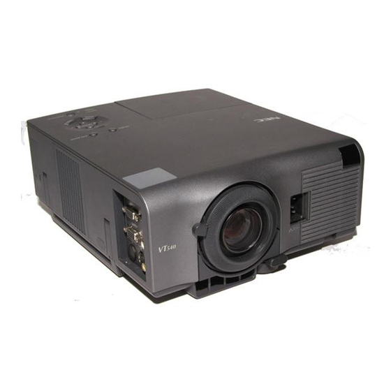
LCD Projector
SERVICE MANUAL
MODEL VT440
Better Service
Better Reputation
Better Profit
SAFETY CAUTION:
Before servicing this chassis, it is important that the service
technician read and follow the "Safety Precautions" and "Product
Safety Notice" in this Service Manual.
WARNING:
SHOCK HAZARD - Use an isolation transformer when servicing.
VT540
VT440G
VT540G
VT440J
VT540J
(Japanese model)
(Japanese model)
PART No.399911031
Advertisement
Chapters
Table of Contents
Troubleshooting

Subscribe to Our Youtube Channel
Related Manuals for NEC VT440


Summary of Contents for NEC VT440
-
Page 1: Lcd Projector
MODEL VT440 VT540 VT440G VT540G VT440J VT540J (Japanese model) (Japanese model) LCD Projector SERVICE MANUAL PART No.399911031 Better Service Better Reputation Better Profit SAFETY CAUTION: Before servicing this chassis, it is important that the service technician read and follow the “Safety Precautions” and “Product Safety Notice”... - Page 2 CONTENTS SAFETY PRECAUTIONS ..........................2-1 USERS MANUAL ............................... 3-1 TROUBLE SHOOTING ............................4-1 METHOD OF ADJUSTMENTS .......................... 5-1 CIRCUIT DESCRIPTION ........................... 6-1 METHOD OF DISASSEMBLY ........................... 7-1 DISASSEMBLY ..............................8-1 PACKAGING ..............................9-1 REPLACEMENT PART LIST ........................... 10-1 CONNECTION DIAGRAMS ..........................11-1 BLOCK DIAGRAM ............................
-
Page 3: Safety Precautions
SAFETY PRECAUTIONS CAUTION RISK OF ELECTRIC SHOCK DO NOT OPEN CAUTION: TO REDUCE THE RISK OF ELECTRIC SHOCK, DO NOT REMOVE COVER. NO USER-SERVICEABLE PARTS INSIDE. REFER SERVICING TO QUALIFIED SERVICE PERSONNEL. This symbol warns the user that uninsulated voltage within the unit may have sufficient magnitude to cause electric shock. - Page 4 SAFTY PRECAUTIONS During servicing carefully observe the following. 5. LAMP Be very careful of the lamp because it generates high 1. OBSERVE ALL PRECAUTIONS heat while it is used at high voltage. When replacing Items and locations that require special care during serv- the bulb, make sure it is cool enough.
- Page 5 LCD Projector MultiSync VT440/VT540 User’s Manual...
-
Page 6: Important Information
EXCEPT Your serial number is located under the name plate label those specified by NEC Technologies in this manual. on the right side of your MultiSync VT440/VT540. Record Failure to comply with this government regulation could it here: void your right to operate this equipment. -
Page 7: Important Safeguards
Important Safeguards CAUTION These safety instructions are to ensure the long life of Do not unplug the power cable from the wall outlet under any your projector and to prevent fire and shock. Please read one of the following circumstances. Doing so can cause damage to the projector: them carefully and heed all warnings. -
Page 8: Lamp Replacement
Do not touch them as the pieces of glass may cause injury. If this happens, contact your NEC dealer for lamp replacement. • Allow a minimum of 30 seconds to elapse after turning off the projector. -
Page 9: Table Of Contents
Getting Started ............E-6 Signal Select ............E-32 What’s in the Box ............E-7 Auto Start .............. E-32 Getting to Know Your MultiSync VT440/VT540 Projector ....E-8 Power Management ..........E-32 Front / Side Features ..........E-8 Power Off Confirmation ......... E-32 Rear / Side Features .......... -
Page 10: Introduction
• Eight pointers are available for your presentation. VT540 Projector The MultiSync VT440/VT540 is one of the very best projectors avail- *1 Do not attempt to mount the projector on a ceiling yourself. able today. The MultiSync VT440/VT540 enables you to project pre-... -
Page 11: What's In The Box
What's in the Box? Make sure your box contains everything listed. If any pieces are missing, contact your dealer. Please save the original box and packing materials if you ever need to ship your MultiSync VT440/VT540 Projector. Lens cap IN P... -
Page 12: Getting To Know Your Multisync Vt440/Vt540 Projector
Getting to Know Your MultiSync VT440/VT540 Projector Front/ Side Features Controls AC Input Connect the supplied power cable’s three-pin plug here. Remote Sensor Remote Sensor Air-Filter (inlet) Slot for Kensington MicroSaver Security System IN P Lens Cap Air-Filter (inlet) - C O... -
Page 13: Rear/ Side Features
Rear/ Side Features Remote Sensor Remote Sensor Built-in Monaural Speaker (1W) Rear Foot Lamp Cover Lamp Cover Screw Card Remote Slot Rear Foot Slot for Card Remote Control Attaching the lens cap to the lens hood with the sup- plied string and rivet The supplied card remote control can be stored in the cabinet. -
Page 14: Top Features
Top Features 1 Source Button 6 Cancel Button Use this button to select a video source such as a PC, VCR or DVD Press this button to exit the menu. Press this button to return the player. adjustments to the last condition while you are in the adjustment or setting menu. -
Page 15: Terminal Panel Features
Terminal Panel Features AUDIO INPUT OUTPUT PC-CONTROL S-VIDEO VIDEO Slot for Kensington MicroSaver Security System 1. RGB Input Connector(Mini D-Sub 15 pin) 5. Video Input (RCA) Connect your PC or other RGB equipment. Use the supplied sig- Connect a VCR, DVD player, laser disc player, or document cam- nal cable to connect to a PC. -
Page 16: Remote Control Features
Remote Control Features Remote Control 1 Source Button Press to select a video source. AUTO SOURCE 2 Auto Adjust Button ADJ. Use this button to adjust Position-H/V and Pixel Clock/Phase for an optimal picture. Some signals may not be displayed correctly, or in some cases it may take some time for a source to switch be- Vol.+ tween sources. -
Page 17: Operating Range
Operating Range 22 feet 30˚ 22 feet 30˚ E–13... -
Page 18: Installation
One-Touch Tilt button on the front side of the pro- jector to release the Front Adjustable foot. Your MultiSync VT440/VT540 Projector is simple to set up and use. Screen But before you get started, you must first: Side view 1. -
Page 19: Distance Chart
Distance Chart A: Distance between the Screen (inch) lens and the screen cen- C: Horizontal throw dis- tance between screen surface and the lens D: Vertical distance be- tween projector base α 4:3 Diagonal and base of image E: Vertical distance be- tween projector base and screen center Formulas(mm) -
Page 20: Ceiling Installation
Using a mirror to reflect your projector’s image enables you to enjoy tor falls to the ground, you can be injured and the projector a much larger image. Contact your NEC dealer if you need a mirror. severely damaged. If you’re using a mirror and your image is inverted, use the “Menu”... -
Page 21: Wiring Diagram
Wiring Diagram Macintosh or Compatibles (Desktop type or notebook type) Pin adapter for Macintosh (supplied) Speaker System IBM VGA or Compatibles RGB INPUT AUDIO (Desktop type or notebook type) Monitor RGB OUTPUT Signal cable (supplied) To mini D-Sub 15-pin connector on the projector. -
Page 22: Connecting Your Pc
(Desktop type) Audio cable (not supplied) Connecting your PC to your MultiSync VT440 (SVGA)/ VT540 (XGA) projector will enable you to project your computer’s screen image for an impressive presentation. To connect to a PC, simply: 1. Turn off the power to your projector and computer. -
Page 23: Connecting Your Macintosh Computer
V I D Macintosh (Desktop type) NOTE: The new Macintosh computer such as G3 will have the 15 pin HD con- nector. The VT440/VT540's "Plug and Play" data will be downloaded to the Macintosh. Therefore, the Mac adapter will not be necessary. - Page 24 After setting, restart your Macintosh computer. See the following pages for setting of the DIP switches. • When using with a Macintosh, SVGA(800 600 :VT440)/ XGA(1024 768 : VT540) is recommended if your Macintosh supports this mode. • When using with a Macintosh PowerBook, output may not be set to 800 600 unless “mirroring”...
-
Page 25: Connecting An External Monitor
I D E V I D You can connect a separate, external monitor to your VT440/VT540 to simultaneously view on a monitor the image you're projecting. To do so: 1. Turn off the power to your projector, monitor and computer. -
Page 26: Connecting Your Dvd Player
Connecting Your DVD Player DVD player I N P D I O White - C O S - V I D E V I D Optional 15-pin-to-RCA 3 cable (Component V ) Audio Equipment Audio cable (not supplied) White You can connect your projector to a DVD player with component outputs or Video output. To do so, simply: 1. -
Page 27: Connecting Your Vcr Or Laser Disc Player
Connecting Your VCR or Laser Disc Player VCR/ Laser disc player I N P D I O S - V I D E - C O S - V I D E V I D V I D S-video cable (not supplied) White Document camera... -
Page 28: Operation
3.OPERATION Enlarging and Moving a Picture This section describes how to select a computer or video source, how to adjust the picture, and how to customize the menu or projector You can enlarge the area you want up to 400 percent. settings. -
Page 29: Using The Menus
Using the Menus NOTE: An interlaced motion video image may be blurred while the menu is displayed. 1. Press the “Menu” button on the remote control or the projector cabinet to display the Main Menu. 2. Press the buttons on the remote control or the projector cabi- net to highlight the menu for the item you want to adjust or set. -
Page 30: Menu Tree
MENU Tree Sub Menu Basic/ Advanced Menu (all) (all) (VCH) (VCH) Items (all) Hi-Bright/ Eco (all) (all) Normal/ Natural1/ Natural2 (VCH) Aspect Ratio Normal/ Zoom/ Wide Zoom/ Cinema (all) (VCH) Noise Reduction Off/ Low/ Medium/ High (all) (CH) Color Matrix HDTV/ SDTV/ B-Y/R-Y, Cb/Cr, Pb/Pr (all) White Balance... -
Page 31: Menu Elements
Menu Elements Title bar Highlight OK Button Cancel Button Solid triangle Check box Radio button Slide bar ○ ○ ○ ○ ○ ○ ○ ○ ○ ○ ○ ○ ○ ○ ○ ○ ○ ○ ○ ○ ○ ○ ○ ○ ○ ○ ○ ○ ○ ○ ○ ○ ○ ○ ○ ○ ○ ○ ○ ○ ○ ○ ○ ○ ○ ○ ○ ○ ○ ○ ○ ○ ○ ○ ○ ○ ○ ○ ○ ○ ○ ○ ○ ○ Menu windows or dialog boxes typically have the following elements: Title bar: Indicates the menu title. -
Page 32: Menu Descriptions & Functions
However, a picture will be blurred if you correct the keystone angle beyond +12 degrees or more for SXGA signal on VT440. Brightness Adjusts the brightness level or the back raster intensity. -
Page 33: Lamp Mode
Lamp Mode Aspect Ratio This feature enables you to select two brightness mode of the lamp: Aspect Ratio allows you to select the best Aspect mode to display High-Bright and Eco modes. The lamp life can be extended up to your source image. -
Page 34: White Balance
Native mode, the image is displayed full screen using the determines the best resolution for the current RGB input signal Advanced AccuBlend feature. to project an image using NEC’s Advanced AccuBlend Intelli- gent Pixel Blending Technology. Factory Default (Advanced mode) The image can be automatically adjusted for geometry and sta- bility;... -
Page 35: Menu
Menu Menu Display Time (Advanced mode): This option allows you to select how long the projector waits after the last touch of a button to turn off the menu. The preset choices are "Manual", "Auto 3 sec", "Auto 10 sec", and "Auto 30 sec". -
Page 36: Signal Select
[Page2] (Advanced mode) Power Off Confirmation: This option determines whether a confirmation dialog for turn- ing off the projector will appear or not. Keystone Save: This option enables you to save your current keystone settings. Saving your change once affects all sources. The changes are saved when you turn off the projector. -
Page 37: Maintenance
CAUTION: Do not use a lamp other than the NEC replace- ment lamp (VT40LP). Replacing the Lamp Order this from your NEC dealer. -
Page 38: Remote Control Battery Installation
Cleaning or Replacing the Filters [Wireless Card Remote Control] The air-filter sponge keeps the inside of the MultiSync VT440/VT540 Projector free from dust or dirt and should be cleaned after every 100 1. Press firmly and slide the battery cover off. -
Page 39: Power/ Status Light Messages
5. TROUBLESHOOTING This section helps you resolve problems you may encounter while setting up or using the projector. Power/ Status Light Messages Condition Power Indicator Status Indicator Note Standby Steady orange – – Cooling down Blinking green – Blinks green for 30 seconds Lamp in High-Bright mode Steady green –... -
Page 40: Specifications
This section provides technical information about the MultiSync VT440/VT540 Projector’s performance. Model Number VT440 / VT440G / VT540 / VT540G Optical LCD Panel 0.9” p-Si TFT active-matrix, 800 600 dots (VT440) / 1024 768 dots (VT540) Lens Manual zoom, manual focus F2.0 – 2.3 f=35.8 – 43.0 mm... -
Page 41: Troubleshooting
TROUBLESHOOTING Operational checks By making checks on operation under normal working conditions, a certain degree of fault diagnosis can be carried out. Prior to removing the top cover, make the following checks: • Is the POWER indicator lit in orange color in the standby state? •... - Page 42 TROUBLESHOOTING POWER block Problems in the POWER and related circuits often cause typical malfunctions, such as no picture presentation, no power supply to each PWB, no lamp lighting, no fan rotation, and so on. Confirm whether the voltage outputs specified below are available at the POPM connector of the MAIN PWB. PIN No.
- Page 43 TROUBLESHOOTING LCES PWB Are the following signal inputs available at POSV (connected with POSV of the MAIN PWB)? (See the waveform diagram.) PIN No. • 9-14 : Rch video signal (10Vp-p) • 22-27 : Gch video signal (10Vp-p) • 35-40 : Bch video signal (10Vp-p) POSV connector defective Are the following signal outputs available at the respective output pins and test pins of IC5201 (or IC5202, IC5203)? (See the waveform diagram.)
- Page 44 TROUBLESHOOTING LCEX PWB Are the following signal inputs available at POSV (connected with POSV of the MAIN PWB)? (See the waveform diagram.) PIN No. • 3-14 : Rch video signal (10Vp-p) • 16-27 : Gch video signal (10Vp-p) • 29-40 : Bch video signal (10Vp-p) POSV connector defective Are the following signal outputs available at the respective output pins and test pins of IC6201 (or IC6202, IC6203)? (See the waveform diagram.)
- Page 45 TROUBLESHOOTING • Troubleshooting for the I/O block, Sync block, and Video block 1. No video images are generated. (VIDEO system) Are there signals (Y, R-Y, B-Y) at L3401 to 3? See the relevant circuit diagram for waveforms. Check Q3401 to 3, IC3401, and the peripheral circuits. Are there signals at Pins 30 to 32 of IC1104? Check Q1115 to 7 and the peripheral circuits.
- Page 46 TROUBLESHOOTING 2. No RGB images are generated. (VIDEO system) Are there video signals (R, G, B/Y, Cb, Cr) at TP3403 to 5? Check IC3401 and the peripheral circuits. Are there video signal inputs at Pin 30 (R), Pin 28 (G), and Pin 26 (B) of POMI? Check the POMI connector, poor soldering in I/O PWB, and the signal cable.
- Page 47 TROUBLESHOOTING Is there a video signal input (sync provided) at Pin 28 (G) of POMI? Check the POMI connector, poor soldering in I/O PWB, and the signal cable. Check IC1001, Q1000, and the peripheral circuits. Is there a vertical sync signal (in positive polarity) at TP3507? Check IC3502 and the peripheral circuits.
-
Page 48: Method Of Adjustments
METHOD OF ADJUSTMENTS PC Control Software Table of Contents 1. Outline software descriptions 2. Equipment to be used and operating environments 3. Troubleshooting and adjustment procedures 3-1. Replacement of the MAIN PWB 3-2. Replacement of the LCEP PWB 3-3. Replacement of the VIDEO-DEC PWB 3-4. -
Page 49: Outline Software Descriptions
This is the PC control software for servicing adjustments to be conducted during the replacement of the MAIN PWB, LCEP PWB, VIDEO-DEC PWB, or the LCD panel for the LCD projector, the VT440/VT540 Series. This software is used for the adjustment of Sub-Brightness/Sub-Contrast, Flicker, and Ghost, and also the modification of Lamp Usage Time, Filter Usage Time, Panel Usage Time, Projector Usage Time, and Language Selection. -
Page 50: Troubleshooting And Adjustment Procedures
METHOD OF ADJUSTMENTS 3. Troubleshooting and adjustment procedures 3-1. Replacement of the MAIN PWB <Copying of the V-T data, ADJ data, Logo data, and Uniformity data> Let the PJ power supply stay in the STAND BY state and select the [Data] tab for servicing software. Make data read/write according to the descriptions (1) and (2) below. - Page 51 METHOD OF ADJUSTMENTS (2) Adjustment of Component Sub-Brightness/Sub-Contrast Select [Component] in the Auto ADJ box. Make adjustments by any method of (a), (b) or (c) below. (a) Auto adjustment As an adjusting signal, enter a split color bar (7 colors) with the use of a Component signal genera- tor.
- Page 52 METHOD OF ADJUSTMENTS (2) Adjustment of Ceiling Check [Ceiling]. Click the [ON] button in the Test Pattern box in order to display the internal horizontal line signal. If this [ON] button is clicked continuously, a changeover action takes place in the toggle mode in the course of R->...
-
Page 53: Replacement Of The Lcep Pwb
METHOD OF ADJUSTMENTS 3-2. Replacement of the LCEX (LCES) PWB <Adjustment of Flicker> Make the similar adjustments as those for the replacement of the MAIN PWB. 3-3. Replacement of the VIDEO-DEC PWB <Adjustment of Sub-Brightness/Sub-Contrast> Make the similar adjustments as those for the replacement of the MAIN PWB. 3-4. -
Page 54: Various Functional Descriptions
<Model Name> The present PJ data are acquired and discrimination of the model is carried out. In the case of the VT440 System, [VT440] is displayed. For the VT540 System, [VT540] is displayed. <Read and Write of the V-T Data>... - Page 55 METHOD OF ADJUSTMENTS <Read and Write of the ADJ Data> At the time of the replacement of the MAIN PWB, this function is used to write the V-T data (adjusting data used for shipment and various user setting values), which have been used before the replacement, in the new MAIN PWB.
- Page 56 METHOD OF ADJUSTMENTS 4-2. Sub-B/C <Sub-Brightness/Sub-Contrast> This function is used for the manual adjustment of Sub-Brightness/Sub-Contrast. The data are independently possessed by the three types of signals for RGB, Component, and Video. The signal data selected in the Auto ADJ box are acquired and they are respectively displayed for R(Cr)/G(Y)/ B(Cb) beside the scroll bar on the screen.
-
Page 57: Data
METHOD OF ADJUSTMENTS <Auto ADJ> This function is used for the selection and automatic adjustment of signals to be used for the adjustment of Sub-Brightness/Sub-Contrast. Select the required adjusting signal from RGB/Component/Video. According to the selected signal, signal changeover (RGB/Component-> RGB1, Video-> Video), data read, and data reset (signal being displayed) are carried out. -
Page 58: Flicker
METHOD OF ADJUSTMENTS 4-3. Flicker <Floor/Ceiling> This function is used for the adjustment of flicker. The data are sustained for Floor and Ceiling, respectively. The present data of the PJ are acquired and displayed on the screen. The data acquired firstly (at the time of starting of the adjusting software) are stored as the initial value and displayed on the left of the arrow mark. -
Page 59: Ghost
R/G/B, respectively. Adjusting range: “VT540” 00H - 2FH “VT440” 00H - 17H <Test Pattern> This function is used when an internal Test Pattern is displayed for ghost adjustment. -
Page 60: Lamp
METHOD OF ADJUSTMENTS 4-5. Lamp <Change time (Lamp Usage Time)> This function is used when changing the lamp usage time. The action for the modification of the lamp usage time should be carried out while the PJ power supply is made to stay in the Standby mode. - Page 61 METHOD OF ADJUSTMENTS <Change time (Filter Usage Time)> This function is used when changing the filter usage time. The action for the modification of the filter usage time should be carried out while the PJ power supply is made to stay in the Standby mode. At the beginning (at the time of adjusting software start), the projector data are acquired and stored as the initial values.
- Page 62 METHOD OF ADJUSTMENTS <Change time (Projector Usage Time)> This function is used when changing the Projector Usage Time. The action for the modification of the projector usage time should be carried out in the standby mode at all times. The present projector data are acquired and displayed on the screen. The data acquired at the beginning (at the time of adjusting software start) are stored as the initial values and displayed on the left of the arrow mark.
- Page 63 METHOD OF ADJUSTMENTS 4-6. Option <Power> Used for Power ON/OFF. When ON/OFF is selected, the power supply is turned ON and OFF. <Input Select> Used for input changeover. The input line is changed over to the selected input. <Test Pattern> Used to display the various internal test patterns.
- Page 64 The default setting for the PJ is 38400 bps. <CRC> The VT440/540 is provided with a protective function not to perform unwanted POWER ON when the internal data (except for the adjusting data) have been changed. The CRC function is used in the case of failure in POWER ON due to the modification of the internal data.
-
Page 65: Error Messages
METHOD OF ADJUSTMENTS 5. Error messages “RS xxxxxx” A communication error in conjunction with the PJ. Examine the connections and confirm whether the main power supply of the PJ is turned ON or not. “ACK Data length error,” “R-CheckSum error,” “Write error” A communication error in conjunction with the PJ. -
Page 66: Disassembly
METHOD OF ADJUSTMENTS 1. Adjustment of the optical axis (Shadow adjustment) 1-1. Tools required 1-2. Preliminary arrangements before adjustments 1-3. Method of shadow adjustment in each color Fig. 1 Flow Chart of Shadow Adjustment Fig. 2 Objective Blocks to be Adjusted 2. - Page 67 METHOD OF ADJUSTMENTS 1. Adjustment of the optical axis (Shadow adjustment) This adjustment is intended to remove color stain (defined as shadow hereafter) that may appear at the edge part of the projected screen possibly caused by a problem around the optical engine block. Adjustments can be carried out based on the flow chart in Fig.
- Page 68 METHOD OF ADJUSTMENTS 1-3-2. Vertical shadow adjustment for B (when the shadow color is yellow) Replace the RL2 vertical adjusting screw. (Part name: Nylock screw (HLSS4*6), Part No.: 24N04751) Then, follow the working procedures below by the use of a ball driver (opposite side 2.0mm). Sufficiently loosen the RL2 vertical fixing screw (Part name: special screw (PL-HM2.5*6), Part No.: 12851741) (in 1 position).
- Page 69 METHOD OF ADJUSTMENTS Start of adjustment Check the vertical shadows of R, G, B. Vertical shadows No shadows Shadows present present Shadows of G and R present Adjust the vertical shadows of G and R. (1-3-1) No shadows Check the vertical shadows of B. Shadows present Shadows of only B present...
- Page 70 Fig. 2...
- Page 71 METHOD OF ADJUSTMENTS 2. Adjustment of the Polarizing Plate It is unnecessary to adjust the polarizing plate. If the polarizing plate is damaged, however, it is necessary to replace the polarizer and the mounting metal fitting (POL). <Replacement procedures> 2-1. Tools required The following tools are required for this replacement: <Tools to be used>...
- Page 72 METHOD OF ADJUSTMENTS Fig. 3 5-25...
- Page 73 METHOD OF ADJUSTMENTS Picture Quality Decision Criteria Judge units that satisfy the following criteria as acceptable. (1) Pixel Mis-Convergence The pixel Mis-Convergence of the red and blue shall be as specified below in reference to the green. • 1 pixel or less in the center area •...
-
Page 74: Circuit Description
CIRCUIT DESCRIPTION LC driver block 1. Circuit configuration PWB configuration • MAIN PWB Used for the phase decode processing of the RGB video signals, the level adjustment, and the genera- tion of various timing signals. • Used for the level shift processing of the panel drive timing signals for the LCES PWB (SVGA) and the LCEX PWB (XGA), and also for the generation of panel auxiliary signals. - Page 75 CIRCUIT DESCRIPTION Interface between MAIN and LCES, LCEX P0SV P0ST Pin No. Signal name Pin No. Signal name A+17.5V DGND A+17.5V VIDR/2 VIDR/4 VIDR/6 VIDR/8 D+5V VIDR/10 DGND VIDR/12 VIDR/1 VIDR/3 ENB1R VIDR/5 ENB2R VIDR/7 DGND VIDR/9 ENB1G VIDR/11 ENB2G AGND ENB1B VIDG/2...
- Page 76 CIRCUIT DESCRIPTION List of I C control ICs (Output block) Item name Circuit symbol Function Slave address Remarks M62398FP IC5103/IC6103 Serial D/A Output video level adjustment, flicker adjustment Interface with the LC panel SVGA panel XGA panel PORES/GES/BES POREX/GEX/BEX Pin No. Signal name Pin No.
- Page 77 CIRCUIT DESCRIPTION I/O Block, VIDEO Processor Block, SYNC Block 1. I/O terminals Video input • RCA PHONO terminal for composite video signal input (1 system) • S VIDEO input terminal (1 system) RGB input (Application to the component input through the conversion cable) •...
- Page 78 CIRCUIT DESCRIPTION 3. I/O PWB block RGB OUT circuit The RGB video signal input entered in Pin 15 of the Mini D-SUB is amplified at the 6dB amplifier (IC4000; AD8013AR) so that it attains 1Vp-p at the time of 75Ω termination. The H Sync output is generated through the buffer circuit (Q4000 to Q4002).
- Page 79 CIRCUIT DESCRIPTION RGB/Component signal processor and A/D converter block The video signal input entered in Pin 15 of the Mini D-SUB is fed to the A/D converter IC (IC3401: CXA3506R) through the buffer circuit. In the case of a component signal, only the chroma signals (Pb, Pr, Cb, Cr) are entered after their levels have been lowered at the attenuator of -6B.
- Page 80 CIRCUIT DESCRIPTION Signal Processor Block 1. PLL block The PLL block is incorporated in the A/D converter (IC3401). In the PLL block, the dot clock signal is generated in synchronization with the horizontal sync signal input. This clock signal is fed to the ENDEAVOR (IC3502). 2.
-
Page 81: Method Of Disassembly
METHOD OF DISASSEMBLY 1. Main unit diagonal view... - Page 82 METHOD OF DISASSEMBLY 2. FILTER ASSY A/FILTER ASSY B/LAMP COVER ASSY/CAP (1) Loosen the one screw , and take out the LAMP COVER ASSY. (2) Take out the FILTER ASSY A/FILTER ASSY B/ and the CAP. FILTER ASSY B LAMP COVER ASSY Screw FILTER ASSY A...
- Page 83 METHOD OF DISASSEMBLY 3. TOP COVER ASSY/STAY R/FILTER F (3) Remove the FILTER F. (1) Remove the five screws , and take out the TOP COVER ASSY. Note) Refer to P7-4 and P7-5. (2) Remove the two screws , and take out the STAY Screw 1 STAY R TOP COVER ASSY...
- Page 84 METHOD OF DISASSEMBLY 1: Hold both sides of the set with both hands at Part A. Apply a force to Part B in the direction of the arrow (diagonally toward the top of the set). In this case, the force being applied should be as low as possible in order not to damage the switch.
- Page 85 METHOD OF DISASSEMBLY 3: Remove the top cover in the direction of the arrow. At that time, this action should be done in the direction of rotation, with the front side of the cabinet regarded as a fulcrum. When mounting the top cover, the procedures should be reverse as those for the removal.
- Page 86 METHOD OF DISASSEMBLY 4. LAMP BOX SASSY (1) Loosen the two screws , and take out the LAMP BOX SASSY. LAMP BOX SASSY Screw...
- Page 87 METHOD OF DISASSEMBLY 5. MAIN PWB ASSY (1) Remove the four screws , and take out the MAIN PWB ASSY. Screw MAIN PWB ASSY...
- Page 88 METHOD OF DISASSEMBLY 6. LCEX PWB ASSY (VT540 System)/LCES PWB ASSY (VT440 System)/KEY PWB ASSY/ BARRIER (B/M) (1) Remove the two screws and two studs, and (2) Remove the three screws , and take out the take out the LCEX PWB ASSY (VT540 System) KEY PWB ASSY and the BARRIER (B/M).
- Page 89 METHOD OF DISASSEMBLY 7. POWER UNIT (1) Remove the three screws and the two screws , and take out the POWER UNIT. Screw POWER UNIT Screw...
- Page 90 METHOD OF DISASSEMBLY 8. OPTICAL ENGINE ASSY (1) Remove the five screws , and take out the OP- TICAL ENGINE ASSY. Screw OPTICAL ENGINE ASSY 7-10...
- Page 91 METHOD OF DISASSEMBLY 9. OPTICAL ENGINE ASSY 7-11...
- Page 92 METHOD OF DISASSEMBLY 10. ZOOM LENS (SK) (1) Remove the four screws , and take out the ZOOM LENS (SK). Screw 1 ZOOM LENS (SK) Screw 1 7-12...
- Page 93 METHOD OF DISASSEMBLY 11. COVER (INHAIL DUCT) ASSY/INHAIL DUCT (SK) ASSY/STOPPER (XDP) ASSY (1) Remove the COVER (INHAIL DUCT) ASSY. (3) Remove the three screws and the stud, and (2) Remove the two screws , and take out the take out the INHAIL DUCT (SK) ASSY. STOPPER (XDP) ASSY.
- Page 94 METHOD OF DISASSEMBLY 12. COVER OPT (SK) (1) Remove the eight screws , and take out the COVER OPT (SK). Screw Screw COVER OPT (SK) 7-14...
- Page 95 METHOD OF DISASSEMBLY 13. OPT BASE SASSY/BARRIER (XDP) (1) Remove the two screws , and take out the OPT BASE SASSY. (2) Remove the BARRIER (XDP). Screw BARRIER (XDP) OPT BASE SASSY 7-15...
- Page 96 METHOD OF DISASSEMBLY 14. R POL SASSY/G POL SASSY/B POL SASSY (1) Remove the R,G,B POL SASSY. B POL SASSY R POL SASSY G POL SASSY 7-16...
- Page 97 METHOD OF DISASSEMBLY 15. MIRROR ASSY1 (SKT)/DICHROIC MIRROR 1 (SK)/DICHROIC MIRROR 2 (SK)/ MIRROR 0 (SK)/MIRROR 2 (SK)/RELAY LENS ASSY 1 (SK)/RL2 SASSY/SPRING S (1) Remove the one screw , and take out the MIR- (4) Remove ten pieces of SPRING S, and take out ROR ASSY1 (SKT).
- Page 98 METHOD OF DISASSEMBLY 16. FL SASSY/IT1 SASSY/IT2 SASSY/BARRIER 2 (SEPARATE BASE)/ BARRIER 1 (SEPARATE BASE)/THERMOSTAT (1) Remove the two screws , and take out the (4) Remove the two screws , and take out the BAR- THERMOSTAT. RIER 1 (SEPARATE BASE). (2) Remove the two screws , and take out the IT1 (5) Remove the two screws...
- Page 99 METHOD OF DISASSEMBLY 17. DUCT CASE (SK) ASSY (1) Remove the three screws , and take out the DUCT CASE (SK) ASSY. DUCT CASE (SK) ASSY Screw 7-19...
- Page 100 METHOD OF DISASSEMBLY 18. BRACKET (I/O) ASSY/I/O PWB ASSY/REMOCON CASE UNIT (1) Remove the one screw , and take out the (3) Remove the one screw , and take out the BRACKET (I/O) ASSY. REMOCON CASE UNIT. (2) Remove the three screws , and take out the I/O PWB ASSY.
- Page 101 METHOD OF DISASSEMBLY 19. SCIROCCO FAN (1) Remove the five screws , and take out the SCIROCCO FAN. Screw SCIROCCO FAN 7-21...
- Page 102 METHOD OF DISASSEMBLY 20. HANDLE/BRACKET (HANDLE)/SHAFT (HANDLE)/SPEAKER/SPEAKER HOLDER/ FILTER S/FILTER R (1) Remove the two screws , and take out the two (3) Remove the one screw , and take out the BRACKET (HANDLE). SPEAKER HOLDER and the SPEAKER. (2) Remove the two SHAFT (HANDLE), and then take out the HANDLE.
- Page 103 MEMO...
- Page 104 DISASSEMBLY • MAIN BODY...
- Page 105 DISASSEMBLY • OPTICAL ENGINE...
- Page 106 DISASSEMBLY • RL2 SASSY...
- Page 107 DISASSEMBLY • POL SASSY CONDENSER LENS ASSY PLATE (POL) POLARIZER POL and POLARIZER ASSY R POL ASSY G POL ASSY B POL ASSY SCREW POL SASSY PART LIST R POL SASSY G POL SASSY B POL SASSY COMPONENTS PART NO PART NO PART NO PLATE(POL)
- Page 108 DISASSEMBLY • FL SASSY...
-
Page 109: Packaging
PACKAGING Packing Procedures 1. VT440... - Page 110 PACKAGING 2. VT440G...
- Page 111 PACKAGING 3. VT540...
- Page 112 PACKAGING 4. VT540G...
-
Page 113: Replacement Part List
2. When you place an order for spare parts, please refer to number specified. The letters NSP in the table indicate non-service parts. the respective service manual and mention the right parts number on your P.O. Sheets. 1. VT440 SYMBOL PART NO DESCRIPTION *** PWB ASSYS ***... - Page 114 VT440 *** APPEARANCE PARTS *** 12851741 SPECIAL SCREW(PL-HM2.5*6) 910E2511 PL-CPIMS*2.5*6*15BF 24N04721 SCREW(WASCHER 2.5*10) 910E2521 PL-CPIMS*2.5*8*15BF 910E2531 PL-CPIMS*2.5*10*15BF 910E306L PL-CPIMS*3*10*3GF 24N04781 SPECIAL SCREW(PL-HM3*16) 910D3066 PL-CPIMS*3*10*3KF 91613061 SCREW,#2CBTS*3*10*15BF 91614031 SCREW,#2CBITS*4*12*15BF 24N03651 STUD(D-SUB,M2.6*3GF) 24N04352 SPECIAL SCREW(M4) 24N04691 STAD(M3*14,M/FM) 24N04701 STAD(M3*17.5,M/FM) 24N04731 SCREW(CBIPS2*6,PRECOAT) 24N04741...
- Page 115 LABEL,SERIAL MANUFACTURE 25765841 LABEL(1*10) 25781322 LABEL,BARCODE 24BS6621 REMOCON CASE UNIT 24C02681 CLIP(DS-9UL) 24C05911 TILT RIVET 24D11271 BOTTOM COVER 24D11421 TOP COVER(VT440) 24DT7492 BOTTOM COVER ASSY 24DT7665 TOP COVER ASSY 24F29461 TILT FOOT(R) 24F30581 CUSHION FOOT(R) 24F31771 HOLDER(CL1) 24F31781 HOLDER(CL2) 24F31791...
- Page 116 VT440 *** APPEARANCE PARTS *** 24F32091 LAMP BOX(B) 24F32561 TILTINSERT 24FT6951 24FT7312 LAMP COVER ASSY 24FT7351 FILTER ASSY A 24FT7362 FILTER ASSY B 24FT7401 TILT FOOT ASSY 24FT7431 SEPARATE BASE(SK) ASSY 24FT7441 DUCT CASE(SK)ASSY 24FT7451 INHAIL DUCT(SK)ASSY 24FT7461 COVER(INHAIL DUCT)ASSY...
- Page 117 24MU5511 FILLER C,CARTON 24MU5521 PROTECTION BAG 70810792 POWER CORD U3 L3 BK,L(L) 78038751 QUICK REFERENCE VT540/440 78038771 WARRNTY CARD 78411391 USE'S MANUAL VT540/VT440 E10(M52) 79646751 RD-366E 79646941 VT CABLE SET *** VT CABLE SET *** 73499369 CABLE,RGB 70599172 ADAPTER D15P-MD15P...
- Page 118 VT440G 2. VT440G SYMBOL PART NO DESCRIPTION *** PWB ASSYS *** 935Y1D01 LCES PWB ASSY 935Y1F01 MAIN PWB ASSY 935X7NA1 I/O PWB ASSY 935X7NB1 KEY PWB ASSY *** ELECTRICAL PARTS & MISCELLANEOUS PARTS *** 79646932 POWER UNIT 73895159 CABLE,FFC 30P*38 P0.5 SO 73895160 CABLE,FFC 40P*38 P0.5 SO POBES...
- Page 119 VT440G *** APPEARANCE PARTS *** 12851741 SPECIAL SCREW(PL-HM2.5*6) 910E2511 PL-CPIMS*2.5*6*15BF 24N04721 SCREW(WASCHER 2.5*10) 910E2521 PL-CPIMS*2.5*8*15BF 910E2531 PL-CPIMS*2.5*10*15BF 910E306L PL-CPIMS*3*10*3GF 24N04781 SPECIAL SCREW(PL-HM3*16) 910D3066 PL-CPIMS*3*10*3KF 91613061 SCREW,#2CBTS*3*10*15BF 91614031 SCREW,#2CBITS*4*12*15BF 24N03651 STUD(D-SUB,M2.6*3GF) 24N04352 SPECIAL SCREW(M4) 24N04691 STAD(M3*14,M/FM) 24N04701 STAD(M3*17.5,M/FM) 24N04731 SCREW(CBIPS2*6,PRECOAT) 24N04741 SCREW(CFIPS3*6*15BF) 24N04751 SPECIAL SCREW(HLSS4*6)
- Page 120 LABEL,SERIAL MANUFACTURE 25765841 LABEL(1*10) 25781322 LABEL,BARCODE 24BS6621 REMOCON CASE UNIT 24C02681 CLIP(DS-9UL) 24C05911 TILT RIVET 24D11271 BOTTOM COVER 24D11421 TOP COVER(VT440) 24DT7492 BOTTOM COVER ASSY 24DT7665 TOP COVER ASSY 24F29461 TILT FOOT(R) 24F30581 CUSHION FOOT(R) 24F31771 HOLDER(CL1) 24F31781 HOLDER(CL2) 24F31791...
- Page 121 VT440G *** APPEARANCE PARTS *** 24F32091 LAMP BOX(B) 24F32561 TILTINSERT 24FT6951 24FT7312 LAMP COVER ASSY 24FT7351 FILTER ASSY A 24FT7362 FILTER ASSY B 24FT7401 TILT FOOT ASSY 24FT7431 SEPARATE BASE(SK) ASSY 24FT7441 DUCT CASE(SK)ASSY 24FT7451 INHAIL DUCT(SK)ASSY 24FT7461 COVER(INHAIL DUCT)ASSY 24FT7471 STOPPER (XDP)ASSY 24G05271...
- Page 122 24MU5511 FILLER C,CARTON 24MU5521 PROTECTION BAG 70810004 POWER CORD E3 L3 BK,L(L) 78038751 QUICK REFERENCE VT540/440 78038771 WARRNTY CARD 78411391 USE'S MANUAL VT540/VT440 E10(M52) 79646751 RD-366E 79646941 VT CABLE SET *** VT CABLE SET *** 73499369 CABLE,RGB 70599172 ADAPTER D15P-MD15P...
- Page 123 VT540 3. VT540 SYMBOL PART NO DESCRIPTION *** PWB ASSYS *** 935X7D01 LCEX PWB ASSY 935X7F01 MAIN PWB ASSY 935X7NA1 I/O PWB ASSY 935X7NB1 KEY PWB ASSY *** ELECTRICAL PARTS & MISCELLANEOUS PARTS *** 79646932 POWER UNIT 73895159 CABLE,FFC 30P*38 P0.5 SO 73895160 CABLE,FFC 40P*38 P0.5 SO POBES...
- Page 124 VT540 *** APPEARANCE PARTS *** 12851741 SPECIAL SCREW(PL-HM2.5*6) 910E2511 PL-CPIMS*2.5*6*15BF 24N04721 SCREW(WASCHER 2.5*10) 910E2521 PL-CPIMS*2.5*8*15BF 910E2531 PL-CPIMS*2.5*10*15BF 910E306L PL-CPIMS*3*10*3GF 24N04781 SPECIAL SCREW(PL-HM3*16) 910D3066 PL-CPIMS*3*10*3KF 91613061 SCREW,#2CBTS*3*10*15BF 91614031 SCREW,#2CBITS*4*12*15BF 24N03651 STUD(D-SUB,M2.6*3GF) 24N04352 SPECIAL SCREW(M4) 24N04691 STAD(M3*14,M/FM) 24N04701 STAD(M3*17.5,M/FM) 24N04731 SCREW(CBIPS2*6,PRECOAT) 24N04741 SCREW(CFIPS3*6*15BF) 24N04751 SPECIAL SCREW(HLSS4*6)
- Page 125 VT540 *** APPEARANCE PARTS *** 12JS1531 DICHROIC MIRROR 1(SK) 12JS1541 DICHROIC MIRROR 2(SK) 12JS1551 POLARIZER 1(SK) 12JS1561 POLARIZER 2(SK) 12JS1571 POLARIZER 3(SK) 12JS1581 REFLCTER LAMP(SK) 12JS1601 COVER GLASS(SK) 12JS1711 POLARIZER 3(SKK) 12JS1721 MIRROR ASSY1(SKT) 18775141 LABEL,SERIAL MANUFACTURE 25765841 LABEL(1*10) 25781322 LABEL,BARCODE 24BS6621 REMOCON CASE UNIT...
- Page 126 VT540 *** APPEARANCE PARTS *** 24F32091 LAMP BOX(B) 24F32561 TILTINSERT 24FT6951 24FT7311 LAMP COVER ASSY 24FT7351 FILTER ASSY A 24FT7361 FILTER ASSY B 24FT7401 TILT FOOT ASSY 24FT7431 SEPARATE BASE(SK) ASSY 24FT7441 DUCT CASE(SK)ASSY 24FT7451 INHAIL DUCT(SK)ASSY 24FT7461 COVER(INHAIL DUCT)ASSY 24FT7471 STOPPER (XDP)ASSY 24G05271...
- Page 127 24MU5511 FILLER C,CARTON 24MU5521 PROTECTION BAG 70810792 POWER CORD U3 L3 BK,L(L) 78038751 QUICK REFERENCE VT540/440 78038771 WARRNTY CARD 78411391 USE'S MANUAL VT540/VT440 E10(M52) 79646751 RD-366E 79646941 VT CABLE SET *** VT CABLE SET *** 73499369 CABLE,RGB 70599172 ADAPTER D15P-MD15P...
- Page 128 VT540G 4. VT540G SYMBOL PART NO DESCRIPTION *** PWB ASSYS *** 935X7D01 LCEX PWB ASSY 935X7F01 MAIN PWB ASSY 935X7NA1 I/O PWB ASSY 935X7NB1 KEY PWB ASSY *** ELECTRICAL PARTS & MISCELLANEOUS PARTS *** 79646932 POWER UNIT 73895159 CABLE,FFC 30P*38 P0.5 SO 73895160 CABLE,FFC 40P*38 P0.5 SO POBES...
- Page 129 VT540G *** APPEARANCE PARTS *** 12851741 SPECIAL SCREW(PL-HM2.5*6) 910E2511 PL-CPIMS*2.5*6*15BF 24N04721 SCREW(WASCHER 2.5*10) 910E2521 PL-CPIMS*2.5*8*15BF 910E2531 PL-CPIMS*2.5*10*15BF 910E306L PL-CPIMS*3*10*3GF 24N04781 SPECIAL SCREW(PL-HM3*16) 910D3066 PL-CPIMS*3*10*3KF 91613061 SCREW,#2CBTS*3*10*15BF 91614031 SCREW,#2CBITS*4*12*15BF 24N03651 STUD(D-SUB,M2.6*3GF) 24N04352 SPECIAL SCREW(M4) 24N04691 STAD(M3*14,M/FM) 24N04701 STAD(M3*17.5,M/FM) 24N04731 SCREW(CBIPS2*6,PRECOAT) 24N04741 SCREW(CFIPS3*6*15BF) 24N04751 SPECIAL SCREW(HLSS4*6)
- Page 130 VT540G *** APPEARANCE PARTS *** 12JS1531 DICHROIC MIRROR 1(SK) 12JS1541 DICHROIC MIRROR 2(SK) 12JS1551 POLARIZER 1(SK) 12JS1561 POLARIZER 2(SK) 12JS1571 POLARIZER 3(SK) 12JS1581 REFLCTER LAMP(SK) 12JS1601 COVER GLASS(SK) 12JS1711 POLARIZER 3(SKK) 12JS1721 MIRROR ASSY1(SKT) 18775141 LABEL,SERIAL MANUFACTURE 25765841 LABEL(1*10) 25781322 LABEL,BARCODE 24BS6621 REMOCON CASE UNIT...
- Page 131 VT540G *** APPEARANCE PARTS *** 24F32091 LAMP BOX(B) 24F32561 TILTINSERT 24FT6951 24FT7311 LAMP COVER ASSY 24FT7351 FILTER ASSY A 24FT7361 FILTER ASSY B 24FT7401 TILT FOOT ASSY 24FT7431 SEPARATE BASE(SK) ASSY 24FT7441 DUCT CASE(SK)ASSY 24FT7451 INHAIL DUCT(SK)ASSY 24FT7461 COVER(INHAIL DUCT)ASSY 24FT7471 STOPPER (XDP)ASSY 24G05271...
- Page 132 24MU5511 FILLER C,CARTON 24MU5521 PROTECTION BAG 70810004 POWER CORD E3 L3 BK,L(L) 78038751 QUICK REFERENCE VT540/440 78038771 WARRNTY CARD 78411391 USE'S MANUAL VT540/VT440 E10(M52) 79646751 RD-366E 79646941 VT CABLE SET *** VT CABLE SET *** 73499369 CABLE,RGB 70599172 ADAPTER D15P-MD15P...
- Page 133 VT440J 5. VT440J SYMBOL PART NO DESCRIPTION *** PWB ASSYS *** 935Y1D01 LCES PWB ASSY 935Y1F01 MAIN PWB ASSY 935Y1NA1 I/O PWB ASSY 935Y1NB1 KEY PWB ASSY *** ELECTRICAL PARTS & MISCELLANEOUS PARTS *** 79646932 POWER UNIT 73895164 CABLE,FFC 30P*38 P0.5 SU 73895165 CABLE,FFC 40P*38 P0.5 SU POBES...
- Page 134 VT440J *** APPEARANCE PARTS *** 12851741 SPECIAL SCREW(PL-HM2.5*6) 910E2511 PL-CPIMS*2.5*6*15BF 24N04721 SCREW(WASCHER 2.5*10) 910E2521 PL-CPIMS*2.5*8*15BF 910E2531 PL-CPIMS*2.5*10*15BF 910E306L PL-CPIMS*3*10*3GF 24N04781 SPECIAL SCREW(PL-HM3*16) 910D3066 PL-CPIMS*3*10*3KF 91613061 SCREW,#2CBTS*3*10*15BF 91614031 SCREW,#2CBITS*4*12*15BF 24N03651 STUD(D-SUB,M2.6*3GF) 24N04352 SPECIAL SCREW(M4) 24N04691 STAD(M3*14,M/FM) 24N04701 STAD(M3*17.5,M/FM) 24N04731 SCREW(CBIPS2*6,PRECOAT) 24N04741 SCREW(CFIPS3*6*15BF) 24N04751 SPECIAL SCREW(HLSS4*6)
- Page 135 VT440J *** APPEARANCE PARTS *** 12JS1531 DICHROIC MIRROR 1(SK) 12JS1541 DICHROIC MIRROR 2(SK) 12JS1551 POLARIZER 1(SK) 12JS1561 POLARIZER 2(SK) 12JS1571 POLARIZER 3(SK) 12JS1581 REFLCTER LAMP(SK) 12JS1601 COVER GLASS(SK) 12JS1711 POLARIZER 3(SKK) 12JS1721 MIRROR ASSY1(SKT) 25617801 TAPE FORM 24BS6621 REMOCON CASE UNIT 24C02681 CLIP(DS-9UL) 24C05911...
- Page 136 VT440J *** APPEARANCE PARTS *** 24FT6951 24FT7312 LAMP COVER ASSY 24FT7351 FILTER ASSY A 24FT7362 FILTER ASSY B 24FT7401 TILT FOOT ASSY 24FT7431 SEPARATE BASE(SK) ASSY 24FT7441 DUCT CASE(SK)ASSY 24FT7451 INHAIL DUCT(SK)ASSY 24FT7461 COVER(INHAIL DUCT)ASSY 24FT7471 STOPPER (XDP)ASSY 24G05271 PUSH BUTTON 24G05301 PUSH BOTTON(TILT) 24H24411...
- Page 137 VT440J *** APPEARANCE PARTS *** 24J15871 CUSHION (RL2) 24J15961 CUSHION2(INHAIL DUCT) 24J15971 BARRIER(B/M) 24J15981 SHEET A(SP) 24J15991 SHEET B(SP) 24J16021 CUSHION(FILTER) 24J16041 CUSHION(10*6.5*T13) 24K24401 INLAY(I/O) 24L11331 LABEL(8*28) 24L34401 CAUTION LABEL(SERVICE) 24L41311 CAUTION 24L42201 CAUTION LABEL(EARTH) 24L43971 NAME PLATE 24L44001 LABEL POS 24L44741 LABEL(VT LAMP) 24L44981...
- Page 138 VT440J *** PRINTED & PACKING MATERIALS *** 16761791 SERIAL LABEL 24M15261 ENVELOPE(VL CLUB) 24M16261 ACCESSORY BAG 24MU4771 SPACER F 24MU4781 SPACER R 24MU4951 CARTON BOX 24MU5511 FILLER C,CARTON 24MU5521 PROTECTION BAG 70800855 POWER CORD J3 L3 BK,L(L) 78037724 VL CLUB LEAFLET 78038111 VL CLUB REGISTRATION CARD 78038761...
- Page 139 VT540J 6. VT540J SYMBOL PART NO DESCRIPTION *** PWB ASSYS *** 935X7D01 LCEX PWB ASSY 935X7F01 MAIN PWB ASSY 935X7NA1 I/O PWB ASSY 935X7NB1 KEY PWB ASSY *** ELECTRICAL PARTS & MISCELLANEOUS PARTS *** 79646932 POWER UNIT 73895164 CABLE,FFC 30P*38 P0.5 SU 73895165 CABLE,FFC 40P*38 P0.5 SU POBES...
- Page 140 VT540J *** APPEARANCE PARTS *** 12851741 SPECIAL SCREW(PL-HM2.5*6) 910E2511 PL-CPIMS*2.5*6*15BF 24N04721 SCREW(WASCHER 2.5*10) 910E2521 PL-CPIMS*2.5*8*15BF 910E2531 PL-CPIMS*2.5*10*15BF 910E306L PL-CPIMS*3*10*3GF 24N04781 SPECIAL SCREW(PL-HM3*16) 910D3066 PL-CPIMS*3*10*3KF 91613061 SCREW,#2CBTS*3*10*15BF 91614031 SCREW,#2CBITS*4*12*15BF 24N03651 STUD(D-SUB,M2.6*3GF) 24N04352 SPECIAL SCREW(M4) 24N04691 STAD(M3*14,M/FM) 24N04701 STAD(M3*17.5,M/FM) 24N04731 SCREW(CBIPS2*6,PRECOAT) 24N04741 SCREW(CFIPS3*6*15BF) 24N04751 SPECIAL SCREW(HLSS4*6)
- Page 141 VT540J *** APPEARANCE PARTS *** 12JS1531 DICHROIC MIRROR 1(SK) 12JS1541 DICHROIC MIRROR 2(SK) 12JS1551 POLARIZER 1(SK) 12JS1561 POLARIZER 2(SK) 12JS1571 POLARIZER 3(SK) 12JS1581 REFLCTER LAMP(SK) 12JS1601 COVER GLASS(SK) 12JS1711 POLARIZER 3(SKK) 12JS1721 MIRROR ASSY1(SKT) 25617801 TAPE FORM 24BS6621 REMOCON CASE UNIT 24C02681 CLIP(DS-9UL) 24C05911...
- Page 142 VT540J *** APPEARANCE PARTS *** 24F32601 WASHER(LAMP) 24FT6951 24FT7312 LAMP COVER ASSY 24FT7351 FILTER ASSY A 24FT7362 FILTER ASSY B 24FT7401 TILT FOOT ASSY 24FT7431 SEPARATE BASE(SK) ASSY 24FT7441 DUCT CASE(SK)ASSY 24FT7451 INHAIL DUCT(SK)ASSY 24FT7461 COVER(INHAIL DUCT)ASSY 24FT7471 STOPPER (XDP)ASSY 24G05271 PUSH BUTTON 24G05301...
- Page 143 VT540J *** APPEARANCE PARTS *** 24J15861 CUSHION (FL) 24J15871 CUSHION (RL2) 24J15961 CUSHION2(INHAIL DUCT) 24J15971 BARRIER(B/M) 24J15981 SHEET A(SP) 24J15991 SHEET B(SP) 24J16021 CUSHION(FILTER) 24J16041 CUSHION(10*6.5*T13) 24K24401 INLAY(I/O) 24L11331 LABEL(8*28) 24L34401 CAUTION LABEL(SERVICE) 24L41311 CAUTION 24L42201 CAUTION LABEL(EARTH) 24L43941 NAME PLATE 24L43991 LABEL POS 24L44741...
- Page 144 VT540J *** PRINTED & PACKING MATERIALS *** 16761791 SERIAL LABEL 24M15261 ENVELOPE(VL CLUB) 24M16261 ACCESSORY BAG 24MU4771 SPACER F 24MU4781 SPACER R 24MU4921 CARTON BOX 24MU5511 FILLER C,CARTON 24MU5521 PROTECTION BAG 70800855 POWER CORD J3 L3 BK,L(L) 78037724 VL CLUB LEAFLET 78038111 VL CLUB REGISTRATION CARD 78038761...
- Page 147 VIDEO/SYNC BLOCK...
- Page 169 PRINTED IN JAPAN 0002MI0030 01150034 (VT440) 01150035 (VT440G) 01151012 (VT440J) 01150031 (VT540) 01150032 (VT540G) 01151011 (VT540J)
- Page 170 PRINTED IN JAPAN 0005MI0030 01150034 (VT440) 01150035 (VT440G) 01151012 (VT440J) 01150031 (VT540) 01150032 (VT540G) 01151011 (VT540J)
Need help?
Do you have a question about the VT440 and is the answer not in the manual?
Questions and answers