Table of Contents
Advertisement
Quick Links
DVD PLAYER
DV-563A-S
DV-50A
THIS MANUAL IS APPLICABLE TO THE FOLLOWING MODEL(S) AND TYPE(S).
Model
Type
DV-563A-S
KUXU/CA
DV-50A
KUXU/CA
¶ DV-50A is a system(s) component.
Component
DVD RECEIVER
AUDIO/VIDEO MULTI-CHANNEL RECEIVER
DVD PLAYER
For details, refer to "Important symbols for good services".
PIONEER CORPORATION
PIONEER ELECTRONICS (USA) INC. P.O. Box 1760, Long Beach, CA 90801-1760, U.S.A.
PIONEER EUROPE NV Haven 1087, Keetberglaan 1, 9120 Melsele, Belgium
PIONEER ELECTRONICS ASIACENTRE PTE. LTD. 253 Alexandra Road, #04-01, Singapore 159936
PIONEER CORPORATION 2003
Power Requirement
AC120V
AC120V
System
EX-500
VSX-50
DV-50A
4-1, Meguro 1-chome, Meguro-ku, Tokyo 153-8654, Japan
DV-563A-S
Region No.
1
&&PG######$$
1
&&PG######$$
Service Manual
RRV2798
RRV2797
RRV2740
This service manual
T-ZZE JUNE 2003 printed in Japan
ORDER NO.
RRV2740
Serial No.
Confirm 3rd & 4th
alphabetical letters.
Remarks
Advertisement
Table of Contents

Related Manuals for Pioneer DV-563A-Sl DV-50A


Summary of Contents for Pioneer DV-563A-Sl DV-50A
-
Page 1: Dvd Player
PIONEER CORPORATION 4-1, Meguro 1-chome, Meguro-ku, Tokyo 153-8654, Japan PIONEER ELECTRONICS (USA) INC. P.O. Box 1760, Long Beach, CA 90801-1760, U.S.A. PIONEER EUROPE NV Haven 1087, Keetberglaan 1, 9120 Melsele, Belgium PIONEER ELECTRONICS ASIACENTRE PTE. LTD. 253 Alexandra Road, #04-01, Singapore 159936... -
Page 2: Safety Information
PIONEER Service Manual. A subscription to, or additional copies Also test with plug reversed of, PIONEER Ser vice Manual may be obtained at a (Using AC adapter Earth nominal charge from PIONEER. plug as required) - Page 3 [ Important symbols for good services ] In this manual, the symbols shown-below indicate that adjustments, settings or cleaning should be made securely. When you find the procedures bearing any of the symbols, be sure to fulfill them: 1. Product safety You should conform to the regulations governing the product (safety, radio and noise, and other regulations), and should keep the safety during servicing by following the safety instructions described in this manual.
-
Page 4: Table Of Contents
CONTENTS SAFETY INFORMATION ............................. 2 1. SPECIFICATIONS ............................5 2. EXPLODED VIEWS AND PARTS LIST ......................6 2.1 PACKING ..............................6 2.2 EXTERIOR SECTION..........................8 2.3 FRONT PANEL SECTION ........................10 2.4 LOADING MECHA ASSY ........................12 2.5 TRAVERSE MECHA ASSY-S ........................14 3. -
Page 5: Specifications
1. SPECIFICATIONS Number of channels ..... . . 2 General Jacks ......RCA jack System . -
Page 6: Exploded Views And Parts List
2. EXPLODED VIEWS AND PARTS LIST NOTES: Parts marked by "NSP" are generally unavailable because they are not in our Master Spare Parts List. mark found on some component parts indicates the importance of the safety factor of the part. Therefore, when replacing, be sure to use parts of identical designation. -
Page 7: Power Cable
PACKING parts List Mark No. Description Part No. Mark No. Description Part No. Paper Board VHC1100 > Power Cable ADG7021 Packing Case See Contrast table (2) Audio / Video Cable See Contrast table (2) Sheet (750 x 600 x 0.5) Z23-007 Remote Control Unit See Contrast table (2) -
Page 8: Exterior Section
2.2 EXTERIOR SECTION Refer to "2.4 LOADING MECHA. ASSY". DV-563A-S Only Refer to "2.3 FRONT PANEL SECTION". DV-563A-S... - Page 9 EXTERIOR SECTION parts List Mark No. Description Part No. Mark No. Description Part No. PCB Base VNE2278 DVDM Assy VWS1563 PCB Base VNE2310 JCKB Assy VWV1942 NSP 18 S Earth Plate VNF1128 • • • • • Adapter 3L VNL1960 >...
-
Page 10: Front Panel Section
2.3 FRONT PANEL SECTION DV-563A-S... - Page 11 DV-563A-S/KUXU/CA and DV-50A/KUXU/CA are constructed the same except for the following : DV-563A-S/ DV-50A/KUXU/ Mark No. Symbol and Description KUXU/CA 1 FLKY Assy VWG2427 VWG2430 10 Front Panel Assy VXA2576 VXA2575 11 Pioneer Name Plate VAM1129 Not used 11 Pioneer Name Plate B Not used PAN1376 DV-563A-S...
-
Page 12: Loading Mecha Assy
2.4 LOADING MECHA ASSY Note : Refer to Refer to "2.5 TRAVERSE MECHA. ASSY-S". " Application of Lubricant". To DVDM CN101 (Pickup Assy-S) To DVDM CN104 (Stepping Motor) Daifree To DVDM CN102 (Spindle Motor) GEM1036 Lubricating Oil GYA1001 Lubricating Oil GYA1001 LOADING MECHA ASSY parts List Mark No. - Page 13 Application of Lubricant Lubricating Oil GYA1001 Around the shaft No. 11 Loading Base Lubricating Oil GYA1001 Lubricating Oil Lubricating Oil No. 13 GYA1001 GYA1001 Lubricating Oil Drive Cam Inner side of a ditch Inner side of a ditch GYA1001 Lubricating Oil Lubricating Oil No.
-
Page 14: Traverse Mecha Assy-S
2.5 TRAVERSE MECHA ASSY-S 15 (Torque : 0.15 ± 0.01 N•m) Silicone Adhesive GEM1037 DVDM CN101 (Pickup Assy) 4 (Adjustment screw) Silicone Adhesive GEM1037 Screw Tight 15 (Torque : 0.15 ± 0.01 N•m) GYL1001 (Adjustment spring) To DVDM CN102 (Spindle Motor) DVDM CN104 (Stepping Motor) DV-563A-S... - Page 15 TRAVERSE MECHA ASSY-S parts List Mark No. Description Part No. Spindle Motor VXM1099 Stepping Motor VXM1101 Pickup Assy-S OXX8005 Skew Screw VBA1080 Skew Spring VBH1335 Guide Bar VLL1514 Sub Guide Bar VLL1515 Leaf Spring VNC1023 Joint Spring VNC1019 Support Spring VNC1020 NSP 11 Mecha.Chassis...
-
Page 16: Block Diagram And Schematic Diagram
3. BLOCK DIAGRAM AND SCHEMATIC DIAGRAM 3.1 BLOCK DIAGRAM DVDM ASSY DSD L/PCMDATA0 DSD_L/PCMDATA0 DSD_PCM_0 DSD R DSD_R DSD_PCM_1 DSD C/PCMDATA1 DSD_C/PCMDATA1 DSD_PCM_2 IC701 IC702 DSD LFE DSD_LFE DSD_PCM_3 SAA7893HL/C2 K4S641632F-TC75 SACD IC 64M SDRAM DSD LS/PCMDATA2 DSD_LS/PCMDATA2 DSD_PCM_4 DSD RS DSD_RS DSD_PCM_5 PCM_LSRS_IN... - Page 17 IC201 IC204 JCKB ASSY DSD1791DBR BA4560F Audio DAC (L, R) Audio LPF & Amp. JA101 VOUTL+ PDATA DSD_L DAC L/D0 VOUTL– FRONT DSD_R VOUTR+ DAC R VOUTR– DAC C/D1 SURROUND DAC LFE IC301 IC302 DSD1702EG BA4560F DAC LS/D2 Audio DAC (Ls, Rs) CENTER Audio LPF &...
-
Page 18: Loab Assy And Overall Wiring Diagram
3.2 LOAB ASSY and OVERALL WIRING DIAGRAM Note : When ordering service parts, be sure to refer to "EXPLODED VIEWS and PARTS LIST" or "PCB PARTS LIST". JCKB ASSY (VWV1942) DV-563A-S... -
Page 19: Flky Assy
: RF SIGNAL ROUTE : FOCUS SERVO LOOP LINE : TRACKING SERVO LOOP LINE : STEPPING SERVO LOOP LINE PWSB ASSY FLKY ASSY (VWG2429) (DV-563A-S: VWG2427) (DV-50A: VWG2430) PICKUP ASSY-S (OXX8005) DVDM ASSY SPINDLE STEPPING MOTOR (VWS1563) MOTOR : VXM1101 : VXM1099 LOAB ASSY LOADING... -
Page 20: Dvdm Assy 1/3 [Front End Block]
3.3 DVDM ASSY 1/3 [FRONT END BLOCK] DVDM ASSY (VWS1563) CN601 DV-563A-S... - Page 21 : RF SIGNAL ROUTE : FE_DATA SIGNAL ROUTE : FOCUS SERVO LOOP LINE : TRACKING SERVO LOOP LINE : STEPPING SERVO LOOP LINE 1– 5: Refer to "3.10 WAVEFORMS". DV-563A-S...
-
Page 22: Dvdm Assy 2/3 [Back End Block]
3.4 DVDM ASSY 2/3 [BACK END BLOCK] DVDM ASSY (VWS1563) B/Cb R/Cr S-Y/Y S-C/C B/Cb S-Y/Y S-C/C R/Cr DV-563A-S... - Page 23 : FE_DATA SIGNAL ROUTE : V SIGNAL ROUTE : S-VIDEO OUT C/C SIGNAL ROUTE S-C/C : S-VIDEO OUT Y/Y SIGNAL ROUTE S-Y/Y : R/Cr SIGNAL ROUTE R/Cr : G/Y SIGNAL ROUTE : B/Cb SIGNAL ROUTE S-C/C B/Cb : AUDIO DATA SIGNAL ROUTE : AUDIO(DIGITAL) SIGNAL ROUTE S-Y/Y B/Cb...
-
Page 24: Dvdm Assy 3/3 [Sacd And Power Supply Block]
3.5 DVDM ASSY 3/3 [SACD and POWER SUPPLY BLOCK] DVDM ASSY (VWS1563) : AUDIO DATA SIGNAL ROUTE : AUDIO(DIGITAL) SIGNAL ROUTE DV-563A-S... - Page 25 : The power supply is shown with the marked box. CN104 CN101 DV-563A-S...
-
Page 26: Jckb Assy 1/2 [Audio Block]
3.6 JCKB ASSY 1/2 [AUDIO BLOCK] JCKB ASSY (VWV1942) : The power supply is shown with : V SIGNAL ROUTE the marked box. : S-VIDEO OUT C/C SIGNAL ROUTE S-C/C : S-VIDEO OUT Y/Y SIGNAL ROUTE S-Y/Y : R/Cr SIGNAL ROUTE R/Cr : G/Y SIGNAL ROUTE : B/Cb SIGNAL ROUTE... - Page 27 6– -: Refer to "3.10 WAVEFORMS". 330/10 330/10 DV-563A-S...
-
Page 28: Jckb Assy 2/2 [Video Block]
3.7 JCKB ASSY 2/2 [VIDEO BLOCK] JCKB ASSY (VWV1942) : V SIGNAL ROUTE : S-VIDEO OUT C/C SIGNAL ROUTE S-C/C : S-VIDEO OUT Y/Y SIGNAL ROUTE S-Y/Y : R/Cr SIGNAL ROUTE R/Cr : G/Y SIGNAL ROUTE : B/Cb SIGNAL ROUTE B/Cb : AUDIO(DIGITAL) SIGNAL ROUTE : AUDIO SIGNAL ROUTE... - Page 29 S-C/C S-Y/Y B/Cb S-Y/Y R/Cr S-C/C B/Cb R/Cr =– $: Refer to "3.10 WAVEFORMS". DV-563A-S...
-
Page 30: Flky And Pwsb Assys
3.8 FLKY and PWSB ASSYS FLKY ASSY (DV-563A-S: VWG2427) (DV-50A: VWG2430) DV-563A-S... - Page 31 : The power supply is shown with DV-563A DV-50A the marked box. Not used PWSB ASSY (VWG2429) Not used CN105 FLKY ASSY S102 : FL DIMMER S103 : 4 1 S104 : ¡ ¢ S105 : 7 S106 : 8 S107 : 3 S109 : 0 S110 : RETURN...
-
Page 32: Power Supply Unit
3.9 POWER SUPPLY UNIT DV-563A-S... -
Page 33: Waveforms
3.10 WAVEFORMS Note : The encircled numbers denote measuring point in the schematic diagram. Measurement condition : No. 1 to 2 and 12 to 17 : reference A1 (DVD), T2-chp 19, Color-bar No. 6 to 11 : reference A1 (DVD), T2-chp 1 DVDM ASSY IC301 - pin 99 [RF] IC301 - pin 36 [FG]... - Page 34 DV-563A-S...
-
Page 35: Pcb Connection Diagram
4. PCB CONNECTION DIAGRAM 4.1 LOAB ASSY NOTE FOR PCB DIAGRAMS : 1. Part numbers in PCB diagrams match those in the schematic 3. The parts mounted on this PCB include all necessary parts for diagrams. several destinations. 2. A comparison between the main parts of PCB and schematic For further information for respective destinations, be sure to diagrams is shown below. -
Page 36: Dvdm Assy
4.2 DVDM ASSY SIDE A SIDE A DVDM ASSY (VNP1921-A) CN601 CN101 CN602 CN102 CN105 CN104 Q390 Q6302 Q6972 IC402 IC701 IC601 IC401 IC613 IC301 IC101 IC611 IC400 DV-563A-S... - Page 37 SIDE B SIDE B DVDM ASSY (VNP1921-A) Q6973 Q551 Q521 Q511 Q212 Q211 Q402 Q531 Q541 Q501 Q202 Q201 Q403 Q401 IC603 IC615 IC621 IC608 IC702 IC403 IC201 IC607 IC602 IC604 IC606 IC451 DV-563A-S...
-
Page 38: Jckb Assy
4.3 JCKB ASSY SIDE B C623 C621 Q101 Q751 IC103 IC104 IC204 Q702 Q401 Q301 Q402 Q302 Q751 JCKB ASSY (VNP1919-B) SIDE A CN102 CN602 CN101 CN601 Q202 Q203 R106 R107 IC301 IC401 Q214 Q201 CMKD-P3X R108 Q215 Q216 IC102 R109 C771 R133... - Page 39 SIDE B C806 SIDE A WARNING THIS PRODUCT CONTACT LEAD IN SOLDER AND CERTAIN ELECTRICAL PARTS CONTAIN CHEMICALS WHICH ARE KNOWN TO THE STATE CALIFORNIA TO CAUSE CANCER, BIRTH DEFECTS OR OTHER REPRODUCTIVE HARM. WASH HANDS AFTER HANDLING. HEALTH & SAFETY CODE SECTION 25249.6 - PROPOSITION 65 CONTACT SIDE R272...
-
Page 40: Flky And Pwsb Assys
4.4 FLKY and PWSB ASSYS SIDE A FLKY ASSY (VNP1901-B) CN102 D102 D101 PYKC F4X S102 FL DIM D104 S104 >> S103 FL101 << PWSB ASSY (VNP1901-B) SIDE B PWSB ASSY (VNP1901-B) C154 R138 PWSB VWG2424- CN103 VWG2425- FLKY ASSY (VNP1901-B) DV-563A-S... - Page 41 SIDE A X101 VWG2417- VWG2418- FLKY VWG2419- MENU S111 VWG2420- S109 S114 S113 VWG2421- RIGHT S115 S116 LEFT ENTER S112 VWG2422- VWG2423- TOP MENU S108 EJECT IR101 /STOP VNP1901- /PLAY S110 S117 S118 S119 DC FC PLAY/>> PAUSE/<< DOWN RETURN S107 S106 C101...
-
Page 42: Power Supply Unit
4.5 POWER SUPPLY UNIT SIDE A SIDE B POWER SUPPLY UNIT AC IN [VWR1365] P301 P101 DV-563A-S... -
Page 43: Pcb Parts List
5. PCB PARTS LIST NOTES: Parts marked by "NSP" are generally unavailable because they are not in our Master Spare Parts List. mark found on some component parts indicates the importance of the safety factor of the part. Therefore, when replacing, be sure to use parts of identical designation. When ordering resistors, first convert resistance values into code form as shown in the following examples. - Page 44 Mark No. Description Part No. Mark No. Description Part No. C213, C214, C355, C705 CKSRYB103K50 Q205–Q208, Q304, Q305 2SD2114K C101, C102, C122, C132, C139 CKSRYB104K16 C300 CKSRYB104K16 Q404, Q405 2SD2114K C394 CKSRYB152K50 Q201, Q202, Q214, Q215 DTC114YUA Q301, Q302, Q401, Q402, Q702 DTC114YUA C126, C344 CKSRYB223K50...
- Page 45 Mark No. Description Part No. Mark No. Description Part No. > JA102 JACK VKB1179 P301 PROTECTOR(800mA) AEK7063 > CN601 7P CONNECTOR VKN1211 P101 PROTECTOR(1.6A) AEK7066 CN101, CN102 33P CONNECTOR VKN1519 KN101–KN103 EARTH METAL FITTING VNF1084 FLKY ASSY [VWG2427] SEMICONDUCTORS IC101 PE5374A D102 SLR-343VC...
-
Page 46: Adjustment
6. ADJUSTMENT 6.1 ADJUSTMENT ITEMS AND LOCATION Adjustment Items Adjustment Points (Mechanism Part) [Mechanism Part] Cautions: After adjustment, adjustment screw locks with the Tangential and Radial Height Coarse Adjustment Screw tight. DVD Jitter Adjustment Tangential Radial adjustment adjustment [Electrical Part] screw screw Electrical adjustments are not required. -
Page 47: Necessary Adjustment Points
6.3 NECESSARY ADJUSTMENT POINTS When Adjustment Points Exchange Parts of Mechanism Assy ∗ After adjustment, screw locks Mechanical ~, Ÿ Exchange the Pickup point with the Screw tight. Electric point Mechanical Exchange the Traverse Mechanism point Electric point ∗ After adjustment, screw locks Mechanical Ÿ... -
Page 48: Test Mode
6.4 TEST MODE • The TEST MODE functions that are used only during adjustment are described here. For details, see "7.1.1 TEST MODE". TEST MODE: ON TEST POWER GGF1381 Test mode remote control unit TEST MODE: DISC SET CHECK <TRAY OPEN> DVD, CD OPEN/CLOSE OPEN/CLOSE... -
Page 49: Mechanism Adjustment
6.5 MECHANISM ADJUSTMENT Tangential and Radial Height Coarse Adjustment START Cautions: • Remove the Loading Mecha. Assy. Because there is not a Spacer for height adjustment in • Remove a Spacer for height adjustment adjustment after the second time, will keep it at need. attached to the back side (shaded area) (This parts is Traverse mechanism exclusive use of a model of the Loading Mecha. -
Page 50: Dvd Jitter Adjustment
DVD Jitter Adjustment • Playback method of inner and outer address for the purpose is refererd to "6.4 TEST MODE". • Jitter indication of the monitor is refererd to "7.1.2 DISPLAY SPECIFICATION OF THE TEST MODE". Use disc: GGV1025 START Mechanism Assy •... -
Page 51: General Information
7. GENERAL INFORMATION 7.1 DIAGNOSIS 7.1.1 TEST MODE Test Mode Functional Specification 1 Test mode entry In the power ON state, press the [ESC] (A8-5F) key and [TEST / RANDOM] (A8-5E) key in order of the Test mode remote control unit. - Page 52 ~ Search 1. Search address input entry • It becomes the address input mode when pressing the [+10] (A8-1F) key. (Most significant digit of an address displays "<".) • In this time, display the last address as the initial state. 2.
-
Page 53: Display Specification Of The Test Mode
7.1.2 DISPLAY SPECIFICATION OF THE TEST MODE Character in bold : Item name : Information display 0 Disc sensing [DSC – ∗ ∗ ∗] 1 Address indication The address being traced is displayed in number. The type of discs loaded is displayed. (as for the DVD, indication of decimal number is possible.) [DVD], [CD ], [VCD], [ DVD : ID indication (hexadecimal number, 8 digits) -
Page 54: Functional Specification Of The Shortcut Key
7.1.3 FUNCTIONAL SPECIFICATION OF THE SHORTCUT KEY Only during normal playback, the following shortcut keys can be assigned by pressing a required key after pressing the ESC key of the remote control unit. To quit, press the ESC key Remote Control Remote Control Command Contents Conditions... -
Page 55: Specification Of Model Information Display
7.1.4 SPECIFICATION OF MODEL INFORMATION DISPLAY To display model information : Press the ESC key then the CHAP key. To close the model information display : Press the ESC key. • Display contents Character in bold : Item name : Information display 1 Model name Display it according to model information set from the FL controller. -
Page 56: Functional Specification Of The Service Mode
7.1.5 FUNCTIONAL SPECIFICATION OF THE SERVICE MODE • EDC / ID error FL display (shortcut function) EDC/ID error is displayed on the FL display if you press the CX key while holding the ESC key on the TEST MODE remote control unit pressed. -
Page 57: Mechanical Error History
7.1.6 MECHANICAL ERROR HISTORY Only if a mechanical error (FE error) has been generated, a mechanical error history containing up to the last eight errors is displayed if you press the CHP/TIM key in Service Mode. Errors are displayed in descending order, with the latest one at the top. Description of the mechanical error history 1 Error number Note: When an error has been generated, if the servo state... -
Page 58: Error Code Table
ERROR CODE TABLE Error Name Causes Check Item Possibility of Trouble Remarks FOCUS ERROR (0 x 0∗) Are not there a dirt or a scratch in 1. Pickup the Disc? Does LD become weak? 2. Driver Focus on error 0 x 01 Focus on could not be completed Does the lens move up and down? 3. - Page 59 Error Name Causes Check Item Possibility of Trouble Remarks SPINDLE ERROR (0 x 6∗) Spindle on error 0 x 61 Spindle on could not be completed Spindle off error 0 x 62 Spindle off could not be completed Spindle lost error 0 x 63 Spindle lost control Spindle CAV error 0 x 64 CAV on could not be completed...
-
Page 60: Id Number And Id Data Setting
7.1.7 ID NUMBER AND ID DATA SETTING Caution: For the DVD players compatible with DVD-RW, for playback of a DVD-RW disc (CPRM), it is necessary that an individual ID number and ID data are set for each player. If the ID number and ID data be not properly set in the manner described below, future operations cannot be guaranteed. - Page 61 ID Number Confirmation Mode To enter ID Number Confirmation Mode after the ID number and • Indication of an ID number already set the ID data are set, press the ESC key then the STEREO key. An ID number already set is displayed in the following cases: 1) When the ESC key then the CLEAR key are pressed, user The ID number already set is displayed.
- Page 62 ID DATA Input Mode To enter ID DATA Input Mode, with the ID number set, press the When writing of the data read from the disc to flash ROM is ESC key then the STEREO key. completed, "Rom Write OK!" is displayed. After seeing this message, you can exit this mode by pressing the CLEAR key.
-
Page 63: Trouble Shooting
7.1.8 TROUBLE SHOOTING Check the error history first. (See "7.1.6 MECHANICAL ERROR HISTORY") When the error history is not displayed, see the below table. Symptoms Diagnosis Contents Possible Defective Points The power is not turned on. Check the voltage of EV+3.3V, –28V and FLDC on the POWER POWER SUPPLY Unit SUPPLY Unit. - Page 64 Symptoms Diagnosis Contents Possible Defective Points Does the voltage of CN103-pin 3 and pin 5 on the DVDM Assy change A tray cannot be opened. DVDM Assy normally ? (An opening screen is Front End IC (IC301) Pin 3 (XCLOSE): Tray is fully closed: "H" displayed on the monitor) Tray SW Pin 5 (OPEN): Tray is fully opened: "H"...
-
Page 65: Sequence After Power On
7.1.9 SEQUENCE AFTER POWER ON Flow chart from power on to the picture output STANDBY Power on operation by a user Spindle turn (remote controller key or product key) Read ID information code FL controller receives a message Various setting [FL controller] FL lighting / outputs a power on signal The picture appears... -
Page 66: Disassembly
7.1.10 DISASSEMBLY Note: For performing the diagnosis shown below, the following jig cables for service are required: • GGD1330 ×2 Diagnosis of the PCBs Procedures ; JCKB Assy : ¥ → ø → π DVDM Assy : ¥ → ø → [ Bonnet and Tray Panel Remove the Bonnet by removing the five screws. - Page 67 Front Panel Section Front panel section Remove the six hooks. Remove the front panel section. ×2 JCKB Assy Rear Panel Remove the rear panel by removing the nine screws. ×5 Remove the five screws. JCKB Assy JCKB Assy Remove the JCKB Assy and stand it against the other parts.
- Page 68 DVDM Assy Exchange the two flexible cables for the two jig cables. Jig Cable Remove the three screws. (GGD1330) DVDM Assy DVDM Assy Remove the DVDM Assy and stand it against the other parts. Diagnosis DV-563A-S...
- Page 69 Removing the Traverse Mecha. Assy-S and Pickup Assy-S Loading Mecha. Assy Remove the bridge by removing the one screw. Rear View Pull out the tray, then remove it by pressing the hook. Short-circuit two points of C and D by soldering. Note: After replacement, connect the flexible cable, then remove the soldered joint (open).
- Page 70 Traverse Mecha. Assy-S Flexible cable Dislodge the flexible cables from their factory for the spindle motor Front Side placement. Flexible cable Flexible cable for the pickup for the stepping motor Bottom View Remove the four hooks. Traverse Mecha. Assy-S × 2 Remove the Traverse Mecha.
- Page 71 Pickup Assy-S Front Side Note: The Pickup Assy-S can be removed without removing the Traverse Mecha. Assy-S. (shown as Step ø.) Dislodge the flexible cable for the pickup from its packaged placement. Remove the flexible cable for the pickup. Flexible cable for the pickup Bottom View Adjustment screw Adjustment screw...
- Page 72 Remove the two screws. Pickup Assy-S Note: The screws are secured with epoxy. Make sure to apply epoxy after reattaching the screws. Leaf Spring Joint Spring Silicone Adhesive GEM1037 Joint 03 Silicone Adhesive GEM1037 Arrangement of the flexible cable Arrangement of the flexible cable for the spindle motor for the stepping motor : Conductive surface...
- Page 73 Arrangement of the flexible cable for the pickup : Conductive surface Note: Be sure to move the Pickup Assy-S to the innermost perimeter. Pass the flexible cable below the hook, and fold it back. Fold the flexible cable inward at the position of the reference line.
- Page 74 7.2 IC • The information shown in the list is basic information and may not correspond exactly to that shown in the schematic diagrams. • List of IC STM6316ATXXA, STI5588CVB, SAA7893HL/C2, M63108FP, PE5374A 7 STM6316ATXXA (DVDM ASSY : IC301) • FRONT END IC ¶...
- Page 75 ¶ Pin Function t i c t i c t s i t s i t s i t s i t s i t i s t i s DV-563A-S...
- Page 76 t s i l l u t i s u l l - t l l i c y t i d l l - t l l i c y t i - t l l i c y t i - t l l i c y t i...
- Page 77 l l i l l i t i c l i b y t i DV-563A-S...
- Page 78 7 STI5588CVB (DVDM ASSY : IC601) • BACK END IC ¶ Pin Configuration PIO2[5] CPU_DATA[13] PIO2[6] CPU_DATA[12] PIO2[7] CPU_DATA[11] VDD3_3 CPU_DATA[10] CPU_DATA[9] PIO3[0] CPU_DATA[8] PIO3[1] PIO3[2] VDD1_8 PIO3[3] CPU_DATA[7] PIO3[4] CPU_DATA[6] PIO3[5] CPU_DATA[5] PIO3[6] CPU_DATA[4] PIO3[7] CPU_DATA[3] VDD1_8 CPU_DATA[2] CPU_DATA[1] B_DATA CPU_DATA[0] B_BCLK...
- Page 79 ¶ Block Diagram Internal peripherals Central 2 UARTs, Cache sub-system command port (C2+) C-SSCs, Low power IR transceiver mode MAFE interface Clock DMAs ICache generator Front-end & SRAM link interface Refill control DCache Diagnostic controller JTAG debugging CPU arbiter interface Communications arbiter Programmable...
- Page 80 ¶ Pin Function . r i & l a i d i l l a i d i l . t i l . t i l DV-563A-S...
- Page 81 . r i t i s t i s t i s t i s t i s t i s t i s t i s t s i t s i DV-563A-S...
- Page 82 . r i . ' L ' L ' ' L ' ' L ' : ' L : ' L : ' L c i t i t i c i t i t i c i t i t i c i t i t i c i t...
- Page 83 . r i s t i r i f : ' L : ' L u : ' ' L ' t i r ' t i . ' L ' L ' ' L ' ' L ' ' L ' DV-563A-S...
- Page 84 . r i y t i l a i n i l n i l DV-563A-S...
- Page 85 . r i n i l c i t i t i c i t i t i l b i DV-563A-S...
- Page 86 7 M63018FP (DVDM ASSY : IC101) • BTL Driver IC ¶ Pin Arrangement ¶ Block Diagram DV-563A-S...
- Page 87 ¶ Pin Function DV-563A-S...
- Page 88 Destination (of player) Select (Set with a combinaition of this 3 ports) MS1_0 H" : No System Reset mode , "L" : General mode H" : OEM Model , "L" : Pioneer Model MIC IN Detection of Microphone "H" : Microphone connected CHECKER H"...
- Page 89 Pin Name Function LED5 LED Port 5 LED4 LED Port 4 LED3 LED Port 3 LED2 LED Port 2 LED1 LED Port 1 LED0 LED Port 0 TEST1 (Test Port) TEST0 (Test Port) FIP Segment 17 Output FIP Segment 16 Output FIP Segment 15 Output FIP Segment 14 Output FIP Segment 13 Output...
-
Page 90: Disc / Content Format Playback Compatibility
7.3 DISC / CONTENT FORMAT PLAYBACK COMPATIBILITY Disc / content format ties, including but not limited to: the type of disc used; the type of recording; damage, dirt playback compatibility or condensation on either the disc or the player’s pick-up lens. See below for notes General disc compatibility about particular software and formats. - Page 91 PC-created disc compatibility • When naming MP3 files, add the corre- sponding file name extension (.mp3). • If you record a disc using a personal Files are played according to the file computer, even if it is recorded in a extension.
-
Page 92: Cleaning
7.4 CLEANING Before shipping out the product, be sure to clean the following positions by using the prescribed cleaning tools: Position to be cleaned Cleaning tools Pickup lenses Cleaning liquid : GEM1004 Cleaning paper : GED-008 DV-563A-S... -
Page 93: Panel Facilities
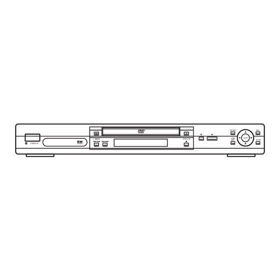
8. PANEL FACILITIES Front panel DV-563A-S STANDBY/ON 10 RETURN Press to switch the player on or into standby. Press to return to a previous menu screen. FL DIMMER 11 HOME MENU Press to dim or brighten the display. Press to display (or exit). Disc tray Press to stop the disc (you can resume play- OPEN/CLOSE... - Page 94 Use the supplied audio/video cable when CONTROL IN / OUT connecting these jacks. Match the colors of For passing remote control signals to other Pioneer components. the jacks and cables for correct stereo sound. AUDIO OUT (5.1ch) Multichannel analog audio outputs for connection to an AV receiver with multi- channel inputs.
- Page 95 Display 14 13 V-PART D.MIX Lights when playing a video part of a DVD During multichannel audio playback, indi- disc. cates that the output signal has been “down- mixed” from the original audio source. This is PRGSVE an automatic function performed by the Lights when the player is set to output player in order to present the most appro- progressive scan video.
- Page 96 Remote control [DV-563A-S] STANDBY/ON Press to switch the player on or into standby. AUDIO Press to select the audio channel or language. SUBTITLE Press to select a subtitle display. Number buttons TOP MENU Press to display the top menu of a DVD disc. ENTER &...
- Page 97 12 PLAY MODE Press to display the Play Mode menu. (You Press to stop the disc (you can resume play- can also get to the Play Mode menu by back by pressing (play)). pressing HOME MENU and selecting Play 23 DISPLAY Mode).
- Page 98 Remote control [DV-50A] OPEN/CLOSE Press to open or close the disc tray. Press to select DVD as the current input. AUDIO Press to select the audio channel or language SUBTITLE Press to select a subtitle display. TOP MENU Press to display the top menu of a DVD disc. ENTER &...
- Page 99 13 LED 24 ENTER Indicates a remote control operation. Use to select menu options, etc. (works exactly the same as the ENTER button in 6 SOURCE above). Press to switch the player on or into standby. 25 ZOOM 15 PLAY MODE Press to change the zoom level.
Need help?
Do you have a question about the DV-563A-Sl DV-50A and is the answer not in the manual?
Questions and answers