
Related Manuals for Altinex TP110


Summary of Contents for Altinex TP110
- Page 1 SPECIAL APPLICATION MANUAL PART NUMBER: 400-0431-001 TP115-110 VGA/COMPONENT+ AUDIO TWISTED PAIR (UTP) TRANSMITTER...
-
Page 2: Table Of Contents
APPLICATION DIAGRAMS........5 DIAGRAM 1: TYPICAL SETUP ......5 DIAGRAM 2: INTERNAL VIEW ......6 INSTALLING YOUR TP115-110......7 OPERATION............... 7 VIDEO EQUALIZATION ........7 TROUBLESHOOTING GUIDE ........ 7 NO DISPLAY............7 NO SOUND............8 ALTINEX POLICY ............8 LIMITED WARRANTY/RETURN POLICY ..8 CONTACT INFORMATION ........8 400-0431-001... -
Page 3: Precautions / Safety Warnings
Any changes or modifications to the unit not To prevent fire or shock, do not expose this unit expressly approved by ALTINEX, Inc. could void to rain or moisture. Do not place the TP115-110 the user’s authority to operate the equipment. -
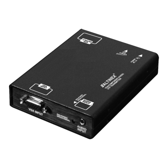
Page 4: About Your Tp115-110
Computer video and audio signals over Twisted Output Pair (UTP) type cable when used together with an Video+ Audio RJ-45 female ALTINEX UTP video receiver, such as the Compatibility TP115-111. Altinex – UTP Standard The TP115-110 is compact and easy to use. The... -
Page 5: Description Of Pe1005
SPECIAL APPLICATION DESCRIPTION OF PE1005 400-0431-001... -
Page 6: Application Diagrams
SPECIAL APPLICATION APPLICATION DIAGRAMS DIAGRAM 1: TYPICAL SETUP TP115-110 TP115-111 400-0431-001... -
Page 7: Diagram 2: Internal View
SPECIAL APPLICATION DIAGRAM 2: INTERNAL VIEW SIGNAL POWER DETECT SYNC PROCESSING VGA HD PAIR1 15 PIN PAIR3 BLUE GREEN PAIR2 OUTPUT CAT 5 PLUG AND PLAY LEFT AUDIO AUDIO STEREO MODULATION 3.5mm RIGHT PAIR4 CLOCK GENERATOR 9V, 1A 2.5mm 400-0431-001... -
Page 8: Installing Your Tp115-110
SPECIAL APPLICATION INSTALLING YOUR TP115-110 OPERATION Step 1. Determine the best location for the The TP115-110 requires only one adjustment to be made for optimal performance. The adjustment is TP115-110 TP115-111. Where video equalization for long cable lengths. possible, locate the TP115-110 as close to the video source as possible and the 7.1 VIDEO EQUALIZATION TP115-111 as close to the receiving... -
Page 9: No Sound
If there is still no sound, see Cause 4. Cause 4: receiving device problem. Solution: Make sure the receiving device has power and is turned on. If there is still no sound, please call Altinex at (714) 990-2300. 400-0431-001...
Need help?
Do you have a question about the TP110 and is the answer not in the manual?
Questions and answers