Table of Contents
Advertisement
Quick Links
Download this manual
See also:
User Manual
Advertisement
Table of Contents

Subscribe to Our Youtube Channel
Related Manuals for Altinex Multi Tasker MT103-122


Summary of Contents for Altinex Multi Tasker MT103-122
- Page 1 MULTITASKER™ MANUAL PART NUMBER: 400-0373-001 MT103-122 VGA + AUDIO TO CAT-5 TRANSMITTER FOR MULTITASKER™ USER’S GUIDE...
-
Page 2: Table Of Contents
VIDEO EQUALIZATION ........16 AUDIO GAIN ............16 TROUBLESHOOTING GUIDE ......16 LED IS NOT RED ..........16 LED IS NOT GREEN (VGA) ......17 NO DISPLAY............17 REMOTE IMAGE QUALITY IS POOR ....18 NO SOUND............18 ALTINEX POLICY ..........18 LIMITED WARRANTY/RETURN POLICY ..18 CONTACT INFORMATION ......18... -
Page 3: Precautions / Safety Warnings
Any changes or modifications to the unit not To prevent fire or shock, do not expose this unit expressly approved by ALTINEX, Inc. could void to rain or moisture. Do not place the MT103-122 the user’s authority to operate the equipment. -
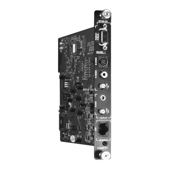
Page 4: About Your Mt103-122
Composite RCA Jack (CAT-5) type cable when used together with an Input Stereo Audio 3.5mm Stereo Jack ALTINEX Twisted Pair Video Receiver, such as the Output RJ-45 Female (1) MT103-123 or DA1931CT. VGA thru UXGA, Stereo Compatibility Audio, C-Video, S-Video The MT103-122 is compact and easy to use. -
Page 5: Product Description
MULTITASKER™ PRODUCT DESCRIPTION... -
Page 6: Application Diagram
MULTITASKER™ APPLICATION DIAGRAM DIAGRAM 1: TYPICAL CONFIGURATION... -
Page 7: Diagram 2 Rj-45 Pinout
MULTITASKER™ DIAGRAM 2 RJ-45 PINOUT Pin Number RJ-45 Output Signals Orange/White Orange Green/White Blue Blue/White Green Brown/White Brown Table 1 Standard 568B Wiring Color Code... -
Page 8: Diagram 3 Internal View
MULTITASKER™ DIAGRAM 3 INTERNAL VIEW MT103-122 CAT-5 Video + Audio Transmitter... -
Page 9: Diagram 4: Dip Switch Settings
MULTITASKER™ DIAGRAM 4: DIP SWITCH SETTINGS AUDIO SYNC PULSE = INTERNAL 50KHZ SYNC PULSE Use for YPbPr, S-Video and C-Video SYNC = HORIZONTAL SYNC PULSE Use with VGA input. VIDEO EQUALIZATION (EQ) HW = HARDWARE EQ. SW = SOFTWARE EQ. -
Page 10: Installing Your Mt103-122
MULTITASKER™ INSTALLING YOUR MT103-122 OPERATION Step 1. Determine the settings required for Audio 7.1 RS-232 CONTROL Sync and if Equalization will be hardware When used in the MultiTasker™ Enclosure, the or software controlled. If necessary to MT103-122 has many advanced remote control change the defaults, see DIAGRAM 4 on capabilities, which are accessible through standard page 8. - Page 11 MULTITASKER™ The Card ID is an assigned value. It is equal to 2. [C] the enclosure slot number in which the card is This command receives the status of the card. installed. The value can range from 1 to 4 up to 1 to 20 depending on the enclosure.
- Page 12 MULTITASKER™ Example: Feedback Prefix Definitions: +MT = Card Number Send the command [?C10] to receive the +VR = Firmware Version feedback for the MT103-122 in slot #10. Each +ON = On/Off Control status field begins with a '+' and ends with the +EQ = Equalization card slot number (ex: C10).
- Page 13 MULTITASKER™ SET EQUALIZATION Upon completion, the system will display the results. If there are no problems, the system will Command Format: [EQ=mCnUi] display the following: = Equalization (m=# from 0 to 50) MEMORY IS GOOD Cn = Card ID (n = slot # from 1 to max slots) Otherwise, failures will be listed.
- Page 14 MULTITASKER™ Command Format: [WRCn…GkUi] Example: Cn = Card ID (n = slot # from 1 to max slots) The cards in slots 1, 2 and 19 are part of Gk = Group number (k = # from 1-8) group 5 in Unit ID 1. Read the member data for Ui = Unit ID (i = # from 0-9) group 5 of Unit ID 1, by sending the command [RDG5U1].
-
Page 15: Summary Of Commands
MULTITASKER™ NOTE: In MTSetup™, send the command [VER] 7.3 SUMMARY OF COMMANDS from the Terminal Window. The system will Card Commands respond with feedback similar to the following: [VER] Receives software version [690-0122-015 690-0123-004 690-0124-018] Receives status of the card Check the last three digits against the numbers above to determine if the MENU MODE option is [CnS]... - Page 16 MULTITASKER™ The system will interrogate the enclosure 7.4.4 MT103-122 MENUS and return a list of cards installed and their Following are the menus available to the slot locations. MT103-122. The first menu is the Main Menu Example: 8 (Slot 8): MT103-122 only.
-
Page 17: Adjustments
MULTITASKER™ 7.4.5 MENU MODE EXAMPLES 7.5 ADJUSTMENTS MENU MODE examples assume The MT103-122 requires only two adjustments to MT103-122 is installed in slot #1. Start by be made for optimal performance. The first is Video clicking the mouse in the Terminal window. Equalization for long cable lengths. -
Page 18: Led Is Not Green (Vga)
If the Send the [C] command to see if display is good, call ALTINEX at there is communication with the (714) 990-2300. card. If there is no feedback, see 8.3 NO DISPLAY... -
Page 19: Remote Image Quality Is Poor
If there is still no sound, see Cause 4. Cause 4: receiving device problem. Solution: Make sure the receiving device has power and is turned ON. If there is still no sound, please call Altinex at (714) 990-2300.
Need help?
Do you have a question about the Multi Tasker MT103-122 and is the answer not in the manual?
Questions and answers