Table of Contents
Advertisement
Quick Links
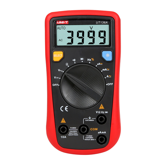
UT136A/B/C/D
Handheld Digital Multimeter
Operating Manual
Safety Information
eter UT
/C/D complies with the standard
IEC/EN
, in pollution degree 2, overvoltage
category (CAT II
V and double insulation. Use
the meter only as
in this operating manual,
otherwise the protection provided by the meter may
be impaired.
.
efore using the meter inspect the case. Do not
use the meter if it is damaged or the case (or part
of the
is removed. Look for cracks or missing
plastic. Pay attention to the insulation around the
connections.
2. Inspect the test leads for damaged insulation or
exposed metal. Replace damaged test leads with
identical model number or electrical specifications
before using the meter.
3. Replace the battery as soon as the battery
indicator "
" Appears. With a low battery, the
meter might produce false readings that can lead to
electric shock and personal injury.
4. When measurement is on / off against the correct
testing position.
5. Do not apply more that the rated voltage, as
marked on the meter in order to avoid possible
electric shock or personal injury and avoid possible
damage to the meter.
. Do not change the measuring range during the
testing as it causes to damage the meter.
7. When each measurement has been completed,
disconnect between the test leads and the circuit
under test connection, then turn the meter power
off and remove the test leads away form the input
terminals of the meter.
8. When the meter working at an effective voltage
over
V in DC and 3 Vrms in AC, special care
should be taken.
9. Do not use or store the meter in an environment of
high temperature and humidity. The performance of
the meter may deteriorate after dampened.
. The internal circuit of the meter shall not be
altered at will to avoid damage of the meter and any
accident.
. Soft cloth and mild detergent should be used to
clean the surface of the meter when servicing. No
abrasive and solvent should be used to prevent the
surface of the meter from corrosion, damage and
accident.
International Electrical Symbols
Double Insulated
Grounding
W
Conforms to Standards of European Union
.
aximum voltage between any terminals and
grounding. Refer to different range input protection
voltage.
2.
A terminal:
A H
Fast Type Ceramic Fuse
3. mA terminal: .5 A H
V Fast Type Ceramic
32
Relative Humidity:
5. Electromagnetism:
Under V/m emission: est Total Accuracy= Spec c
:
7.
attery in meter: 9V
Weight:
Button function and auto power off
HOLD button
Press HOLD to enter and exit hold mode in any mode
except frequency measurement.
2. SELECT button
Press SELECT button to select the alternate
functions including AC/DC voltage, AC/DC current,
auto and manual ranging, frequency and duty cycle.
Used as REL function button under resistance
measurement.
3. AUTO POWER OFF
To preserve battery life, the
into a "sleep" mode if you do not press any button for
around 5 minutes. The
pressing any button, then returns to the display for
the function selected previously. To disable the sleep
mode function, press SELECT button while turning on
the meter.
The buzzer phonate go with every time button be
effectual pressed. When the meter will auto power off
in
minutes the buzzer beeps 5 times.
off there will be a long time buzzer beeps.
Measurement Operation
First check on 9V battery, then turn rotary switch to
the measuring position. If the low battery, "
will be displayed on LCD panel. Nearly to "
on the meter front panel terminal input which alarm
not exceed the testing voltage and current input value
limitation.
A. DC/ AC Voltage Measurement
. In each range, the meter has an input impedance
of
This loading effect can cause measurement
errors in high impedance circuits. If the circuit
impedance is less than or equal to
2. Press SELECT to switch AC or DC voltage
measurement.
3. The display value of AC measurement is effective
value of sine wave( average
4. The
mV AC range can obtain only under
manual mode.
Note:
To avoid possibly damages to the meter, please do
To avoid electrical shock, please pay attention during
the high voltage measurement.
B. Capacitor Measurement
. The
eter will display a xed value as below which
is the
eter internal fixed distributed capacitance
,
value. To ensure accuracy when measuring a small
value of capacitance, the tested value must subtract
this value, REL mode can help on that.
2. It is normal to take several seconds to obtain a
stable reading when testing a high value capacitor.
3. To avoid possibly damages to the meter, please do
not attempt to input higher than
AC.
C. DC/AC Current Measurement
F22 or NEDA
4 or
.
Press SELECT to switch AC or DC current measurement
2.Turn off power to the circuit before the connection
between the test leads across with the object being
measured.
3. Selecting the correct terminal input and turn the
rotary switch to select the measuring function. In case
of no any idea on the value input of the current, just
automatically goes
simply test from the high value to low one.
4. Fuses are located on mA and
eter can be activated by
Never attempt the test lead connect to any circuits
especially on the power supply terminal and may be
hurt.
5. For the safety purpose, less than
for each measurement duration and keep
duration for next measurement during the current
measurement over 5A.
D. Resistance Measurement
power
" sign.
" sign
. The LCD displays "OL" indicating open circuit for
the tested resistor or the resistor value is higher than
the maximum range of the meter.
2. To maintain the resistance measurement accuracy,
discount circuit power and discharge all the high
voltage capacitors during the measuring resistance.
3. The test leads cause
variation during the measurement, In order to obtain
precision readings in
Need to make the short circuit on the test leads and
e
mark the measurement value which show on LCD
display. Then deduct this variation value on the
measurement value which come the meter.
4. If
the error is
than or equal to .5 , check for loose test leads,
incorrect function selection or others.
5. For
stable reading with short test leads for measurement.
Do not input higher than DC
voltage to prevent any damage and accident.
E. Diodes Measurement
V.
y
Disconnect circuit power and discharge all the high
voltage capacitors before measuring resistance.
2. Place the red test lead on the component's anode
and place the back test lead on the component's
cathode, a good diode should still produce a forward
voltage drop reading of
displays "OL" indicating
diodes or the testing the diodes with polarity.
3.
4. Do not input higher than DC
voltage to prevent any damage and accident.
DC and 33V rms
F. Continuity Measurement
A terminal input.
seconds is
.
~ .2
resistance
istance measurement.
reading with shortened test leads is not less
sistance measuremen t greater than
it is normal to take several seconds to obtain a
and AC
~
mV. The LCD
circuit for the tested
V.
and AC
minutes
rms
rms
Advertisement
Table of Contents

Subscribe to Our Youtube Channel
Related Manuals for UNI-T UT136A


Summary of Contents for UNI-T UT136A
- Page 1 C. DC/AC Current Measurement attery in meter: 9V F22 or NEDA 4 or UT136A/B/C/D Handheld Digital Multimeter Weight: Operating Manual Button function and auto power off Safety Information HOLD button Press HOLD to enter and exit hold mode in any mode...
- Page 2 UT136A/B/C/D Operating Manual P/N: 110401103485 1. Set the rotary switch to NCV and remove the test Range Resolution Accuracy lead from the input terminals. ±(1.2% + 2) 2. Place the housing front part with marking towards the 220V/50H eing measured. Distance <10mm, ±(1% + 2)
Need help?
Do you have a question about the UT136A and is the answer not in the manual?
Questions and answers