
Related Manuals for Delta 36-960


Summary of Contents for Delta 36-960
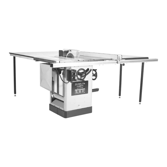
- Page 1 fi UNISAW Left Ti l t 1 0″ Ti l t i n g Arbor Saw (Model 36-960) D AT ED 6-27-00 PA RT NO. 422-40-651-0003 Copyright ' 2000 Delta Machinery...
-
Page 2: Safety Rules
If you have any questions relative to a particular applica- tion, DO NOT use the machine until you have first contacted Delta to determine if it can or should be performed on the product. -
Page 3: Additional Safety Rules For Circular Saw S
ADDITIONAL SAFETY RULES FOR CIRCULAR SAW S 1 . W ARNING: Do not operate your saw until it is com- 1 7 . N E V E R s tart the saw with the workpiece pressed pletely assembled and installed according to the instruc- against the blade. -
Page 4: Machine Data
MACHINE DATA ″ (16 mm) Diameter of Arbor Table: Diameter of Blade 10″ (254 mm) Height 34″ (864 mm) Blade Speed (with 3450 rpm motor) 4000 rpm Size with Extension Wi n g And Biesemeyer Table Board 74″ x 27″ (1880x686 Capacities: ″... - Page 5 F i g . 3 F i g . 5 F i g . 4 BIESEMEYER FENCE SYSTEM NOTE: A common hardware package is used for for fastening front rail to saw table ″ l o n g f l a t h e a d P h i l l i ps screws (2) several different models, therefore you may have 1 3 - -16 x 1...
- Page 6 A S S E M B LY INSTRUCTIONS W ARNING: FOR YOUR OWN SAFETY, DO NOT CONNECT THE SAW TO THE POWER SOURCE UNTIL THE SAW IS COMPLETELY A S S E M B L E D AND YOU HAVE READ AND UNDERSTOOD THE ENTIRE OWNER S MANUAL.
- Page 7 Fig. 12 F i g . 11 ASSEMBLING ON/OFF SWITCH 1 . Loosely assemble switch and switch bracket (A) Fig. 1 2 , t o t h e i n s i d e f r o n t l i p o f t h e l e ft extension wing with hex flat head screw (D), flat washer (E), and hex nut (F) through hole (G) Fig.
- Page 8 Fig. 17 Fig. 16 6 . Insert threaded end of support rod (G) Fig. 16, through slot in back of saw and through hole (H) Fig. 16, in rear trunnion. Fasten support rod (G) Fig. 16, to trunnion using star washer and nut (J) Fig. 17. NOTE: Thread nut (J) onto threaded end of support rod as far as possible by hand.
- Page 9 Fig. 23 Fig. 22 1 0 . Assemble splitter (P) Fig. 22, inside the splitter mounting bracket as shown. Push splitter (P) down as far as possible, making certain bottom edge (T) of splitter (P) i s pa r a l l e l w i t h table surface, and tighten screw (B). 11 .
- Page 10 Fig. 27 Fig. 28 2 . Using template (D) Figures 27 and 28, to check and adjust front rail at both ends of the saw table as shown, to make sure rail (A) is pa r a l l e l w i t h table surface and tighten rail mounting hardware (B).
- Page 11 Fig. 32 Fig. 33 3 . Fasten the leg bracket (L) Fig. 32, to the end piece (J) ″ f l a t h e a d P h i l l i ps s c r e w s , f l a t o f t h e table using the two 1 washers and hex nuts (M) Figs.
- Page 12 Fig. 37 Fig. 38 ″ wood screws (I) supplied. 2 . Figure 37 illustrates one of the legs (H) fastened to the bottom of the extension table with the four wood screws ″ d r i l l b i t , d r i l l t w o t h r o u g h h o l e s t h r o u g h t h e ( I ) .
- Page 13 Fig. 42 Fig. 43 t able board back onto the rear rail, and drill through the h o l e s i n t h e r e a r r a i l t h r o u g h t h e table board, Fig. 41. 7 .
- Page 14 Fig. 48 Fig. 47 ″ sheet t o t h e l e ft rear of the saw cabinet using three metal screws (D). 3 . Insert locking lever (E) Fig. 47, through the hole in the right edge of motor cover (B). Assemble spacer (F) over threads of lever (E), and fasten lever to motor cover with lock nut (G) Fig.
- Page 15 Fig. 52 Fig. 53 Fig. 51, illustrates the miter gage and wrenches stored on the two holder brackets . ASSEMBLING RIP FENCE HOLDER B R A C K E T S Assemble the rip fence holder brackets (A) and (B) Fig. 52, to the four holes located in the right hand side of the ″...
- Page 16 to lock fence in position. NOTE: A magnet (B) Fig. 56, is provided to hold clamp handle (A) in the up position when moving the fence. 3 . The distance the fence is positioned away from the blade is indicated by the witness line (C) Fig. 57, located on the cursor (D).
-
Page 17: Connecting Saw To Power Source
SCREWS (D) AND (E) IS NECESSARY TO ADJUST THE FENCE PARALLEL WITH THE MITER GAGE SLOT. ADJUSTING CLAMPING ACTION OF FENCE LOCKING HANDLE When the fence locking handle (A) is pushed to the down position, as shown in Fig. 61, the fence assembly (B) should be completely clamped to the guide tube (C). -
Page 18: Single Phase Operation
Check with a qualified electrician or service personnel if the grounding instructions are not completely understood, or if in doubt as to whether the tool is properly grounded. Repair or replace damaged or worn cord immediately. SINGLE PHASE OPERATION THREE HORSEPOWER MOTO R S The motor supplied with the Unisaw is single phase, 3 horsepower, and is designed to be operated from a 220-240 volt power system only. - Page 19 ″ t o ″ above ground blades, the blade should be raised the top surface of the material being cut. Wi t h h o l l o w ground blades, the blade should be raised the maximum to provide greater clearance. To raise the saw blade, loosen lock knob (B) Fig.
- Page 20 11 . Loosen locknut (C), and turn adjusting screw (D) counter clockwise, on turn. 1 2 . Turn the blade tilting handwheel until the blade is 45 degrees to the ta b l e . 1 3 . Turn adjusting head screw (D) clockwise, until it just conta c ts the casting on the front trunnion, then tighten l o c k n u t ( C ) , u n t i l i t i s l o c k e d i n t o p l a c e .
-
Page 21: Maintenance
The miter gage body will stop at 90 degrees and 45 degrees both right and left . To r o tate the miter gage body past these p o i n ts, the stop link (D) Fig. 73, must be moved up and out of the way. The head of the miter gage pivots o n a s p e c i a l tapered screw (G) Fig. - Page 22 NOTE: THE USE OF ATTACHMENTS AND A C C E S- SORIES NOT RECOMMENDED BY DELTA M AY RESULT IN THE RISK OF INJURY TO PERSONS AND/OR DAMAGE TO THE TOOL.
- Page 23 When cross-cutting a number of pieces to the same length, a block of wood (B), can be clamped to the fence and used as a cut-off gage as shown in Fig. 80. It is important that this block of wood always be positioned in front of the saw blade as shown.
- Page 24 Fig. 84 Fig. 85 d i fferent knife shapes available make it possible for the operator to produce almost any kind of mouldings, such as various styles of corner moulds, picture frames, table edges, etc. The moulding head consists of a cutterhead in which can be mounted various shapes of steel knives, as shown in F i g .
- Page 25 Fig. 89 Fig. 90 Fig. 88 WOOD WILL CAUSE KICKBACK. When moulding end grain, the miter gage is used. The feed should be slowed up at the end of the cut to prevent s p l i n t e r i n g . I n a l l c u ts, attention should be given the grain, making the cut in the same direction as the grain whenever possible.
- Page 26 Fig. 93 Fig. 94 sticks and feather boards should also be used. Also, the accessory dado head table insert (E) Fig. 91, must be used in place of the standard ta b l e i n s e r t . Fig.
-
Page 27: Parts, Service O R W A R R A N T Y Assista N C E
D e l ta w i l l r e pa i r o r r e p l a c e , a t i ts expense and at its option, any Delta machine, machine pa r t ,...
Need help?
Do you have a question about the 36-960 and is the answer not in the manual?
Questions and answers