Table of Contents
Advertisement
Premium
Digital Humidifier Control
Safety and Installation Instructions
READ COMPLETE INSTALLATION INSTRUCTIONS
AND TEMPLATE BEFORE STARTING INSTALLATION.
WARNING
ATTENTION INSTALLER: This product must be
installed by a qualified heating and air conditioning
contractor. Failure to do so could result in serious
injury from electrical shock.
Advertisement
Table of Contents

Related Manuals for Aprilaire Premium Digital Humidifier Control


Summary of Contents for Aprilaire Premium Digital Humidifier Control
- Page 1 Premium Digital Humidifier Control Safety and Installation Instructions READ COMPLETE INSTALLATION INSTRUCTIONS AND TEMPLATE BEFORE STARTING INSTALLATION. WARNING ATTENTION INSTALLER: This product must be installed by a qualified heating and air conditioning contractor. Failure to do so could result in serious injury from electrical shock.
- Page 2 Troubleshooting ........page 22 2. Sharp edges may cause serious injury from cuts. Use care when cutting plenum openings and THESE INSTALLATION INSTRUCTIONS ARE FOR THE handling ductwork. APRILAIRE DIGITAL HUMIDIFIER CONTROL ONLY! For Aprilaire ® humidifier installation, follow Aprilaire CAUTION Humidifier Installation Instructions.
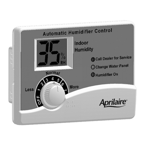
- Page 3 STEP 2: Disassemble the Humidifier Control Figure B Use the “OFF” setting to turn the Remove the knob. Remove the cover by pulling at the bottom and Water Panel Change Indicator OFF. swinging it out and upward. NOTE: When using the Model 50 Current Sensing Relay, the Water Panel Change STEP 3: Check the Mode Switch Indicator MUST be OFF.
- Page 4 DUCT (SHEET METAL) MOUNT: STEP 5: Determine Location for Humidifier Control and Mount Control After location for Control is selected, drill a 3/4 inch hole for the RH sensor (the RH sensor extends from the back of the Humidifier Control must be mounted on the Return Duct, at least Humidifier Control).
- Page 5 SHEET METAL PLATE MANUAL MODE RESISTOR RETURN DUCT RETURN SHEET METAL CUT OPENING IN 24V BLOWER DUCT PLATE RETURN DUCT COMMUNICATION OPERATION SIGNAL WITH APRILAIRE FROM HVAC 8570 THERMOSTAT EQUIPMENT CONTINUOUS 24V 24V SIGNAL TO POWER FOR CONTROL HUMIDIFIER 90-1203 90-1397...
- Page 6 STEP 6: Determine Location for Outdoor STEP 8: Alternate Location for Outdoor Temperature Sensor Temperature Sensor The location of the Outdoor Temperature Sensor must meet The Sensor can also be mounted in the center of either: these three requirements: • PVC fresh air intake pipe for the HVAC system 1.
- Page 7 STEP 9: Route the Wire from Control to Sensor Installing the Humidifier Control for Run wire to the outdoor temperature sensor. Sensor is not Manual Operation affected by lead length. Do not run outdoor temperature sensor alongside wires carrying high voltage (120 VAC or higher). If it is not feasible to install the Outdoor Secure the sensor bracket with a #8 screw.
- Page 8 USING FURNACE ACCESSORY TERMINALS TO DETECT STEP 11: Power Source for Humidifier Control – FURNACE OR BLOWER OPERATION (FIGURE K) Terminals R and C See the furnace manual for voltage and operation of the Wire external 24 VAC transformer into a constant power source accessory terminals.
- Page 9 TRANSFORMER PROVIDED WITH HUMIDIFIER 24 VAC WHITE/YELLOW TRANSFORMER WHITE/BLUE OUTDOOR TEMPERATURE SENSOR OR MANUAL MODE RESISTOR 4851 RELAY APRILAIRE FURNACE TERMINAL STRIP 500 & 600 SERIES YELLOW WIRES 400 SERIES YELLOW WIRE & WHITE WIRE 700 SERIES BROWN WIRES TYPICAL 24 VAC...
- Page 10 HEAT PUMP WIRING (FIGURE N) USING MODEL 50 CURRENT SENSING RELAY TO DETECT FURNACE BLOWER OPERATION (FIGURE P) This configuration allows the humidifier to run whenever the heat pump blower is running (and the Humidifier Control is This option is to be used only if the furnace terminals or calling for humidity).
-
Page 11: System Checkout
• If in Manual Mode and system is installed during cooling season, set the Humidifier Control to “OFF” 8. Instruct the homeowner to refer to the Aprilaire Owner’s Manual for the initial adjustment period. 9. Make sure the red “Call Dealer for Service” light is not flashing. -
Page 12: Troubleshooting
TROUBLESHOOTING PROCEDURE (CONTINUED) Display Error Code: E4: Communication Applies to both Automatic and Manual Operation unless This only applies to systems wired to an Aprilaire Model 8570 indicated otherwise. Thermostat (see Figure Q). SYMPTOM Rotate the Humidifier Control knob to the “Test/Reset” position. - Page 13 SYMPTOM SYMPTOM Humidifier does not operate in “Test/Reset” mode Yellow “Change Water Panel” Light is blinking (see Figure R) TROUBLESHOOTING PROCEDURE TROUBLESHOOTING PROCEDURE • Make sure that the blower is operating and the HVAC Check the condition of the Water Panel and replace it if system is calling for heat.
- Page 14 SYMPTOM SYMPTOM Humidifier operates only in “Test/Reset” mode Humidifier operates constantly • If outdoor temperature is greater than 60°F or less than • If the humidity level in the home is less than the Humidifier -30°F, the Humidifier Control will only operate in the Control knob setting and there is a continuous fan call or “Test/Reset”...
- Page 15 SYMPTOM Humidifier or Humidifier Control “chatters” or clicks On and Off rapidly TROUBLESHOOTING PROCEDURE • Check for steady 22 VAC to 30 VAC across the “R” and “C” terminals of the Humidifier Control with a voltmeter. • Check, with a voltmeter, that the HVAC signal across the “W/G”...
Need help?
Do you have a question about the Premium Digital Humidifier Control and is the answer not in the manual?
Questions and answers