Table of Contents
Advertisement
Advertisement
Table of Contents

Related Manuals for Sailor SAILOR 500 FleetBroadband


Summary of Contents for Sailor SAILOR 500 FleetBroadband
- Page 2 INSTALLATION MANUAL SAILOR 500/250 FleetBroadband...
-
Page 3: Installation Manual
Thrane & Thrane A/S SAILOR 500 FleetBroadband ® SAILOR 250 FleetBroadband ® Installation manual Document number: TT98-125646-C Release date: December 13, 2007... - Page 4 Information in this document is subject to change without notice and does not represent a commitment on the part of Thrane & Thrane A/S. We recommend downloading the latest version of the manual from the Thrane & Thrane Extranet. Copyright © 2007 Thrane & Thrane A/S. All rights reserved. Trademark acknowledgements •...
- Page 5 This radiation may be hazardous to humans close to the antenna. During transmission, make sure that nobody gets closer than the recommended minimum safety distance. On the SAILOR 500 FleetBroadband, the minimum safety distance on the focal line to the antenna panel is 1.3 m, based on a radiation level of 10 W/m .
- Page 6 The equipment must be installed with the following minimum safe distances to magnetic steering compass: SAILOR FleetBroadband terminal: min. 0.3 m. SAILOR 500 FleetBroadband antenna: min. 1.0 m SAILOR 250 FleetBroadband antenna: min. 1.1 m Service User access to the interior of the terminal is prohibited. Only a technician authorized by Thrane &...
- Page 7 Grounding, cables and connections To minimize shock hazard, the equipment chassis and cabinet must be connected to an electrical ground. The terminal must be grounded to the ship. For further grounding information refer to Grounding and RF protection on page 109. Do not extend the cables beyond the lengths specified for the equipment.
- Page 8 Mandatory safety instructions to installers & users of SAILOR 250 FleetBroadband ® Use only manufacturer or dealer supplied antenna. Antenna minimum safe distance: 0.415 m. Antenna gain 12.2 dBi referenced to isotropic. The Federal Communications Commission has adopted a safety standard for human exposure to RF (Radio Frequency) energy, which is below the OSHA (Occupational Safety and Health Act) limits.
- Page 9 Warning Maintain a separation distance from the antenna to a person(s) of at least 0.415 m. Note Thrane & Thrane recommends a minimum safety distance of 0.6 m to the SAILOR 250 FleetBroadband antenna. You, as the qualified end-user of this radio device must control the exposure conditions of bystanders to ensure the minimum separation distance (above) is maintained between the antenna and nearby persons for satisfying RF Exposure compliance.
-
Page 10: About The Manual
About the manual Intended readers This is an installation manual for the SAILOR 500 FleetBroadband and the SAILOR 250 FleetBroadband systems. The readers of the manual include installers of the system and service personnel. Personnel installing or servicing the system must be properly trained and authorized by Thrane &... -
Page 11: Related Documents
Thrane & Thrane Extranet and download the latest version, or acquire it from your distributor. Related documents The below list shows the documents related to this manual and to the SAILOR 500 FleetBroadband and SAILOR 250 FleetBroadband systems. Document Title and description... - Page 12 Typography In this manual, typography is used as indicated below: Bold is used for the following purposes: • To emphasize words. Example: “Do not touch the antenna”. • To indicate what the user should select in the user interface. Example: “Select Settings > LAN”. Italic is used to emphasize the paragraph title in cross- references.
-
Page 13: Table Of Contents
Table of contents Chapter 1 System units Introduction ............... 1 Terminal ..............1 SAILOR 500 FleetBroadband antenna .......2 ® SAILOR 250 FleetBroadband antenna .......3 ® IP handset and cradle ..........4 Chapter 2 Installing the system Unpacking ..............7 2.2 Placing the antenna ...........8 2.3 Installing the antenna ..........21 2.4 Placing the terminal .......... - Page 14 Table of contents 4.5 Analog Phone/Fax interface ........50 4.6 ISDN interface ............51 4.7 LAN interface ............53 Discrete I/O interface ..........55 4.9 L-Band interface ............. 58 Chapter 5 Starting up the system Using the SIM card ...........59 5.2 Powering the system ..........61 5.3 Entering the SIM PIN for the terminal ......62 5.4 Operating the system ..........64 Chapter 6...
- Page 15 Table of contents App. B Technical specifications B.1 Overview ..............89 B.2 SAILOR 500 FleetBroadband antenna .....89 ® B.3 SAILOR 250 FleetBroadband antenna .....95 ® B.4 Minimum distance to transmitters......100 B.5 SAILOR FleetBroadband terminal ......101 App. C Grounding and RF protection Why is grounding required? ........109 C.2 General about marine DC systems ......
- Page 16 Table of contents...
-
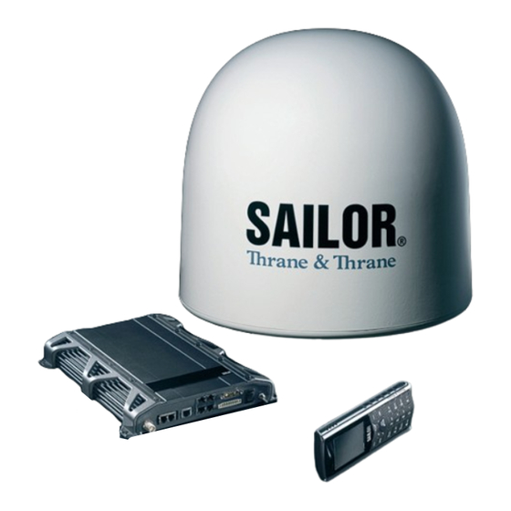
Page 17: System Units
There are two different types of antennas, depending on whether you have a SAILOR 500 FleetBroadband system or a SAILOR 250 FleetBroadband system. 1.2 Terminal The terminal – which contains the primary electronic parts – is designed for wall or desktop installation. -
Page 18: Sailor ® 500 Fleetbroadband Antenna
1.3 SAILOR 500 FleetBroadband antenna ® The SAILOR 500 FleetBroadband antenna is a BGAN Class 8 mechanical tracking antenna, consisting of a stabilized antenna with RF-unit, antenna control unit and GPS antenna. All communication between the antenna and terminal passes through a single coaxial cable. The antenna unit is protected by a fibre glass radome. -
Page 19: Sailor ® 250 Fleetbroadband Antenna
Chapter 1: System units 1.4 SAILOR 250 FleetBroadband antenna ® The SAILOR 250 FleetBroadband antenna is a BGAN Class 9 mechanical tracking antenna. All communication between the antenna and terminal passes through a single coaxial cable. The antenna unit is protected by a thermo-plastic radome. -
Page 20: Ip Handset And Cradle
Chapter 1: System units 1.5 IP handset and cradle 1.5.1 Thrane & Thrane IP handset Besides the normal functions of an IP handset, the Thrane & Thrane IP handset also provides a user interface for the SAILOR FleetBroadband system. The IP handset connects to the LAN interface of the terminal, and is power supplied with Power over Ethernet (PoE) through the LAN interface. - Page 21 Chapter 1: System units 1.5.2 Thrane & Thrane IP cradle The IP cradle serves as a holder for the IP handset. It is power supplied from the terminal using Power over Ethernet (PoE). The cradle is connected to the handset with a coil cord and to the terminal with a standard LAN cable. IP handset and cradle...
- Page 22 Chapter 1: System units IP handset and cradle...
-
Page 23: Installing The System
Unpack your SAILOR FleetBroadband system and check that the following items are present: • TT-3738A SAILOR FleetBroadband terminal • TT-3052A SAILOR 500 FleetBroadband antenna or TT-3050A SAILOR 250 FleetBroadband antenna • TT-3670A IP handset and cradle • Basic cable support kit •... -
Page 24: Placing The Antenna
2.2.1 Obstructions The antenna rotates 360° and down to –25° for the SAILOR 500 FleetBroadband and -60° for the SAILOR 250 FleetBroadband in pitch and roll, to allow for continuous pointing even in heavy sea conditions. Any obstructions within this volume can cause signal degradation. - Page 25 Chapter 2: Installing the system 2.2.2 Radiation hazard The SAILOR 500 FleetBroadband antenna radiates 22 dBW EIRP. This translates to a minimum safety distance of 1.3 m from the antenna while it is transmitting, based on a radiation level of 10 mW/cm The SAILOR 250 FleetBroadband antenna radiates 16.1 dBW EIRP.
- Page 26 Chapter 2: Installing the system 2.2.3 Interference Overview The antenna must be mounted as far away as possible from the ship’s radar and high power radio transmitters (including other Inmarsat based systems), because they may compromise the antenna performance. RF emission from radars might actually damage the antenna.
- Page 27 Chapter 2: Installing the system Radar It is difficult to give exact guidelines for the minimum distance between a radar and the antenna because radar power, radiation pattern, frequency and pulse length/shape vary from radar to radar. Further, the antenna is typically placed in the near field of the radar antenna and reflections from masts, decks and other items in the vicinity of the radar are different from ship to ship.
- Page 28 “d min.” is defined as the shortest distance between the radar antenna (in any position) and the surface of the SAILOR FleetBroadband antenna. X-band (~ 3 cm / 10 GHz) damage distance SAILOR 500 FleetBroadband SAILOR 250 FleetBroadband Radar d min. at 15°...
- Page 29 Chapter 2: Installing the system S-band (~ 10 cm / 3 GHz) damage distance SAILOR 500 FleetBroadband SAILOR 250 FleetBroadband Radar d min. at 15° d min. at 60° d min. at 30° d min. at 75° power vertical vertical...
-
Page 30: Other Precautions
Chapter 2: Installing the system The presences of S-band radar(s) are unlikely to cause any performance degradation – as long as the minimum distances (d min.) listed in the previous section are applied. It is strongly recommended that interference free operation is verified experimentally before the installation is finalized. - Page 31 The antenna mast must be designed to carry the weight of the antenna unit, which is approximately • 16 kg (+ the weight of the mast flange) for the SAILOR 500 FleetBroadband antenna and • 3.9 kg (+ 1.1 kg for the mast mount kit) for the SAILOR 250 FleetBroadband antenna.
- Page 32 Chapter 2: Installing the system SAILOR 250 FleetBroadband antenna mast mounting ® Mast mount kit: The top of the SAILOR 250 FleetBroadband antenna mast should be fitted with the dedicated mounting kit, see SAILOR 250 FleetBroadband mast mount kit ® on page 88.
- Page 33 Alternatively, mount stays or wires to stabilize the mast further. OD (mm) Note The hole in the lower part of the mast is necessary for drainage and ventilation for the SAILOR 500 FleetBroadband antenna. Please refer to Condensation, SAILOR 500 FleetBroadband on page 24. ® Placing the antenna...
- Page 34 Chapter 2: Installing the system The tables in the next sections give some suggested design values for the free part of the mast (shown on the previous page). Note The tables list the values for steel masts. For aluminium masts, the free mast length is reduced to 75% of the values for steel.
- Page 35 500 FleetBroadband antenna mast length ® The below table shows the values for a SAILOR 500 FleetBroadband antenna mast without stays or wires. Note that these values are only guidelines - always consider the environment and characteristics of the ship before deciding on the mast dimensions.
- Page 36 Chapter 2: Installing the system SAILOR 250 FleetBroadband antenna mast length ® The below table shows the values for a SAILOR 250 FleetBroadband antenna mast without stays or wires. Note that these values are only guidelines - always consider the environment and characteristics of the ship before deciding on the mast dimensions.
-
Page 37: Installing The Antenna
Chapter 2: Installing the system 2.3 Installing the antenna 2.3.1 Antenna grounding You may ground the antenna using the mounting bolts. If the antenna cannot or should not be electrically connected directly to the mounting surface, you can use a separate grounding cable to make the connection between the antenna and the common ground to which the terminal is also connected. - Page 38 Chapter 2: Installing the system Recommended antenna cables The table below shows recommended cable types and maximum cable lengths for both SAILOR 500 FleetBroadband and SAILOR 250 FleetBroadband. Cable Type Absolute maximum length G02232-D RG223-D 25 m RG214/U 50 m...
- Page 39 Chapter 2: Installing the system 2.3.3 Important mounting notes Line of sight Place the antenna with free line of sight in all directions to ensure proper reception of the satellite signal. Do not place the antenna close to large objects that may block the signal. Water intrusion After having connected the antenna cable to the antenna - ensure that the connector assembly is properly protected against seawater and corrosion.
- Page 40 500 FleetBroadband ® In some cases there will be condensation inside the radome. The gasket in the bottom center of the SAILOR 500 FleetBroadband antenna is designed to lead any water away from the radome. Gasket with drainage Make sure this draining gasket is not blocked. If the antenna is mounted on a pole, make sure the pole is hollow inside and open at the bottom, allowing water from the gasket to escape and providing ventilation for the antenna.
- Page 41 Chapter 2: Installing the system Vibration, SAILOR 500 FleetBroadband ® Install the antenna where vibrations are limited to a minimum. If you cannot avoid heavy vibrations, we recommend using vibration isolators between the hull/mast and the radome. E.g. use Paulstra isolators (530903 11) together with Paulstra washers.
- Page 42 -25°, which is the maximum rotation angle (pitch and roll) for the SAILOR 500 FleetBroadband antenna. Use M10 bolts for mounting the SAILOR 500 FleetBroadband antenna. The bolt thread must not penetrate more than 12 mm (or 8 turns of the bolt) - and not less than 6 mm (or 4 turns of the bolt)- into the threaded part of the bushes in the radome.
-
Page 43: Placing The Terminal
Chapter 2: Installing the system 2.4 Placing the terminal 2.4.1 Where to place the terminal Temperature conditions The terminal must be placed in a ventilated area with free space around all sides of the unit, except the bottom side. Ambient temperature range is –25° to +55°C. If the terminal is installed in a location where the ambient temperature may exceed 50°C, we recommend placing the terminal where unintentional contact is avoided. -
Page 44: Installing The Terminal
The antenna is connected to the terminal by means of a coax cable. For the SAILOR 500 FleetBroadband antenna the coax cable is connected with a TNC connector at the terminal end and an N connector at the antenna end. - Page 45 Chapter 2: Installing the system Ground stud To ensure that the terminal is grounded – also if the cable is disconnected from the terminal, connect an extra ground wire to the ground stud on the terminal. This ground wire must be a heavy wire or braid cable with a larger diameter than the coax cable.
- Page 46 Chapter 2: Installing the system Connect the foil to the hull by plenty of screws or hard–soldering. Run the foil past the place where the short antenna cable is to be grounded and mount the grounding kit on top of the foil. For further grounding information read Appendix C Grounding and RF protection on page 109.
- Page 47 Chapter 2: Installing the system 2.5.3 Mounting the Basic cable support The Basic cable support comes with the terminal as part of the delivery. When mounted on the terminal the Basic cable support offers a number of holders to which you can secure the cables from the terminal, using cable strips.
- Page 48 Chapter 2: Installing the system 2. Fasten the Basic cable support to the two mounting bushes close to the connector panel on the terminal, using two M4 x 6 mm countersunk screws. 3. Install the terminal as described in Installing the terminal on a bulkhead on page 34 or Installing the terminal on a desktop on page 36.
- Page 49 Chapter 2: Installing the system 2.5.4 Mounting the Extended cable support The Extended cable support is available from Thrane & Thrane. For part number, see Cable support on page 88. The Extended cable support offers connectors and grounding for the antenna cable, as well as a number of holders to which you can secure the cables from the terminal, using cable...
- Page 50 Chapter 2: Installing the system 2.5.5 Installing the terminal on a bulkhead Terminal with no cable support Do as follows to mount the terminal on a bulkhead: 1. Insert four screws through the holes in the mounting bracket and into the mounting surface.
- Page 51 Chapter 2: Installing the system Terminal with Basic cable support First mount the Basic cable support on the terminal as described in Mounting the Basic cable support on page 31. 1. Mount the terminal with the Basic cable support on the bulkhead by inserting four screws through the holes in the mounting bracket and into the mounting surface.
- Page 52 Chapter 2: Installing the system 2.5.6 Installing the terminal on a desktop Four rubber feet make the terminal well suited for desktop installation. Simply place the terminal on a desktop and connect all cables. Make sure the grounding requirements are met. See Grounding and RF protection on page 109.
-
Page 53: Connecting Power
Chapter 3 Connecting power 3.1 Power source There are different options for the power supply: • The 24 V DC ship supply provides power for the terminal. • A 12 V DC supply provides power for the terminal. Be aware that the maximum allowed source impedance is much lower for a 12 V DC supply than for a 24 V DC supply. -
Page 54: Power Cable Selection
Chapter 3: Connecting power 3.2 Power cable selection 3.2.1 Source impedance The length of the terminal power cable depends on the type of cable used and the source impedance of the ship’s DC power installation. The maximum allowed source impedance depends on the utilization of the power range of the terminal DC input (10.5 - 32 V DC;... - Page 55 Chapter 3: Connecting power 3.2.2 Power cable recommendations Overview The terminal is delivered with a power cable, which can be extended according to the recommendations below: Red: + Black: - When extending the power cable, positive and negative supply wires must be installed closely together side by side to keep cable inductance low.
- Page 56 Chapter 3: Connecting power Calculating the maximum power cable extension For 24 V DC operation, the total impedance must be max. 500 mΩ, including the ship’s source impedance. For 12 V DC operation, the total impedance must be max. 85 mΩ, including the ship’s source impedance.
- Page 57 Chapter 3: Connecting power length by connecting two cables in stead of one, or you can use a cable with a larger diameter. Example: Ship supply voltage: 12 V DC Ship source impedance (measured): 50 mΩ Extension cable type: 4 mm (AWG 11) 85 mΩ...
-
Page 58: To Connect Power
Chapter 3: Connecting power 3.3 To connect power Do as follows: 1. Connect the power cable to the ship’s 24 V DC supply according to the recommendations in the previous section. Note If you need a remote on/off function, connect the wires from pin 2 (green wire) and 5 (orange wire) in the power connector to a switch or similar which can connect/disconnect these two pins. -
Page 59: Remote On/Off
Chapter 3: Connecting power 3.4 Remote on/off The terminal has a remote on/off function. When the terminal power switch is in the “on” position you can remote control the power function. By installing a switch that can short-circuit the “Remote on/off” pins (2 and 5) in the power connector you can power the terminal on or off with this “remote switch”. - Page 60 Chapter 3: Connecting power Remote on/off...
-
Page 61: Hardware Interfaces
Chapter 4 Hardware interfaces 4.1 The connector panel The connector panel is placed at one end of the terminal and has the following connectors: • 1 L-Band connector for reception of maritime data • 1 Antenna connector (TNC) • 2 Phone/Fax connectors •... -
Page 62: Antenna Interface On Terminal
4.2.1 Overview The antenna interface on the terminal connects to the TT-3052A antenna in the SAILOR 500 FleetBroadband system or to the TT-3050A antenna in the SAILOR 250 FleetBroadband system. The antenna connector on the terminal is a TNC female connector placed in the connector panel. -
Page 63: Dc Power Input
Chapter 4: Hardware interfaces 4.3 DC power input 4.3.1 Overview The DC power input for the terminal is a 10.5 - 32 V DC; 14 - 5.5 A input with a remote on/off function. The input is protected against reverse polarity. For information on power recommendations and how to connect, see Connecting power on page 37. - Page 64 Chapter 4: Hardware interfaces 4.3.2 Pin-out The power connector is a Mixed D-Sub connector 7W2, control pin male / power pin male. The below table shows the pin-out for the connector and the colors of the corresponding wires. Color of wire in Mixed D-Sub connector, Pin function number...
-
Page 65: Ground Stud
Chapter 4: Hardware interfaces 4.4 Ground stud The terminal has a ground stud with a wing nut. The ground stud is located in the connector panel and is used for grounding the terminal. For information on how to ensure proper grounding of the terminal, see Grounding the terminal on page 28 and Grounding and RF protection on page 109. -
Page 66: Analog Phone/Fax Interface
Chapter 4: Hardware interfaces 4.5 Analog Phone/Fax interface 4.5.1 Overview The terminal has two RJ-11 ports, which can be used for connection of analog phones, fax machines or analog modems. Phone/Fax 1 Phone/Fax 2 4.5.2 Pin-out The Phone/Fax connectors are RJ-11, 6/4 female connectors. The table and figure below show the pin-out for the connectors. -
Page 67: Isdn Interface
Chapter 4: Hardware interfaces 4.6 ISDN interface 4.6.1 Overview The terminal has one ISDN connector for connecting an ISDN phone or an ISDN modem. The ISDN interface supports 56/64 kbps data rate. It is configured as the network side, i.e. Rx is an input and Tx is an output. ISDN interface... - Page 68 Chapter 4: Hardware interfaces 4.6.2 Pin-out The figure and table below show the connector outline and pin assignments. RJ-45 female connector Pin number Pin function not connected not connected Rx+ (c) input Tx+ (d) output Tx- (e) output Rx- (f) input not connected not connected ISDN interface...
-
Page 69: Lan Interface
Chapter 4: Hardware interfaces 4.7 LAN interface 4.7.1 Overview The terminal has four Ethernet LAN ports with Power over Ethernet (PoE). The Ethernet ports are standard IEEE 802.3 af ports using RJ-45 connectors. 4.7.2 Power over Ethernet (PoE) One power supply powers all four interfaces with a floating 48 V DC supply (44 - 57 V DC). - Page 70 Chapter 4: Hardware interfaces 4.7.3 Pin-out The figure and table below show the connector outline and pin assignments. Pin number Pin function RJ-45 female connector TxD+ input (positive PoE) TxD-input (positive PoE) RxD+ output (negative PoE) not connected not connected RxD- output (negative PoE) not connected...
-
Page 71: Discrete I/O Interface
Chapter 4: Hardware interfaces 4.8 Discrete I/O interface 4.8.1 Overview The terminal has an I/O connector with 5 configurable inputs/outputs. The connector is a WieCon Type 8513S connector. A mating I/O connector is included in the delivery. Discrete I/O interface... - Page 72 Chapter 4: Hardware interfaces 4.8.2 Pin-out The figure and table below show the connector outline and pin assignments. WieCon Type 8513S connector Pin number Connection Default configuration GPIO 1 Radio silence acknowledge output, active high GPIO 2 Mute input, active high GPIO 3 Radio silence input, active high...
- Page 73 The output voltage is 9-15 V, 50 mA. For information on how to configure the I/O pins, see the user manual for the SAILOR 500 FleetBroadband and SAILOR 250 FleetBroadband systems. Discrete I/O interface...
-
Page 74: L-Band Interface
Chapter 4: Hardware interfaces 4.9 L-Band interface 4.9.1 Overview The terminal has an L-Band output for automatic delivery of maritime broadcast data. Use a coax cable with an SMA connector to connect a broadcast receiver for maritime data to the L-band output. 4.9.2 Pin-out The figure below shows the pin-out for the SMA female connector. -
Page 75: Chapter 5 Starting Up The System
Chapter 5 Starting up the system 5.1 Using the SIM card 5.1.1 Inserting the SIM card The SIM card is provided by your Airtime Provider. Insert the SIM card as follows: 1. Open the SIM cover in the left side of the connector panel. 2. - Page 76 Chapter 5: Starting up the system Removing the SIM card Note When the SIM card is removed, you cannot use the BGAN menu of the IP handset nor make calls or start data sessions. Only emergency calls are allowed, and only if permitted by the network.
-
Page 77: Powering The System
When the system is powered on, stay clear of the antenna! The antenna emits radio frequency energy, not only when the system is used. Always keep a minimum distance of 1.3 m from the SAILOR 500 FleetBroadband antenna and 0.6 m from the SAILOR 250 FleetBroadband antenna. -
Page 78: Entering The Sim Pin For The Terminal
Chapter 5: Starting up the system 5.3 Entering the SIM PIN for the terminal 5.3.1 Overview You normally have to enter a PIN to use the system. You can enter the PIN using a standard or ISDN phone, the IP handset or the web interface. For information on how to connect the handset or computer you are going to use, refer to the user manual. - Page 79 Chapter 5: Starting up the system After entering the PUK, you must enter a new PIN of your own choice (4 to 8 digits long). Dial the following: <PUK> * <New PIN> * <New PIN> followed by # or off-hook key. Example: If the PUK is 87654321 and the new PIN is 1234, dial 87654321 * 1234 * 1234 followed by # or off-hook key.
-
Page 80: Operating The System
Chapter 5: Starting up the system 5.4 Operating the system 5.4.1 General use The user manual for the SAILOR FleetBroadband systems describes general use of the system and goes through all the functions of the web interface. It also contains a brief description of how to use the Thrane & Thrane IP handset with the terminal. -
Page 81: Chapter 6 Service And Repair
We do not recommend repairing the terminal on board the ship. Replace the defective unit and have it repaired at a qualified workshop on shore. Some of the modules in the SAILOR 500 FleetBroadband antenna can be replaced. See the next sections for details. -
Page 82: Fleetbroadband Antenna
Chapter 6: Service and repair 6.2.2 Modules in the SAILOR 500 FleetBroadband antenna ® Remove the top of the radome to access the antenna modules. The electronic part of the antenna consists of a number of modules. The following modules are available as spare parts. See Appendix A. •... - Page 83 Chapter 6: Service and repair 6.2.3 High Power Amplifier (HPA) Removing the HPA module To remove the HPA from the antenna, do as follows: 1. Disconnect the six plugs indicated in the drawing below. Remember to release connector latches on the connectors. Do not pull the wires - pull the plugs.
- Page 84 Chapter 6: Service and repair 3. Unscrew the four finger screws on the back of the HPA and gently remove the HPA. Replacing modules...
- Page 85 Chapter 6: Service and repair Mounting the HPA module To mount the new HPA, repeat the above procedure in reverse: 1. Fit the threaded studs on the back of the HPA into the holes in the mounting bracket on the antenna. Apply a small amount of Loctite 243 onto each of the four threaded studs before mounting the finger screws on the threaded studs.
- Page 86 Chapter 6: Service and repair 6.2.4 Antenna Tracking Board/Low Noise Amplifier (ATB/LNA) Removing the ATB/LNA module To remove the ATB/LNA module from the antenna, do as follows: 1. Disconnect the six plugs indicated in the drawing below. Important notes: • Remember the exact position of each plug, so you do not connect to the wrong connector when installing the new module.
- Page 87 Chapter 6: Service and repair 2. Gently lift the cable holder and release the cables. 3. Unscrew the two finger screws and gently remove the ATB/LNA module. Replacing modules...
- Page 88 Chapter 6: Service and repair Mounting the ATB/LNA module To mount the new ATB/LNA module, repeat the above procedure in reverse: 1. Fit the threaded studs on the antenna into the holes in the sides of the ATB/LNA module, and fasten the finger screws with torque 1.2 Nm. 2.
- Page 89 Chapter 6: Service and repair 6.2.5 GPS module Removing the GPS module To remove the GPS module from the antenna, do as follows: 1. Disconnect the plug from the GPS module. Remember to release the connector latch on the connector. Do not pull the wires - pull the plug. 2.
- Page 90 Chapter 6: Service and repair Mounting the GPS module To mount the new GPS module, repeat the above procedure in reverse: 1. Fit the GPS module over the dedicated four threaded bushes on the mounting plate above the HPA module. 2.
-
Page 91: Chapter 7 Troubleshooting
Chapter 7 Troubleshooting 7.1 Reset button 7.1.1 How to access the Reset button The terminal has a Reset button placed next to the SIM slot behind the SIM cover. The functions of this button is described in the next section. To press the Reset button, use a pointed device. - Page 92 Chapter 7: Troubleshooting 7.1.2 Function of the Reset button The Reset button on the terminal has the following functions: Action Function With the terminal The terminal IP address and IP netmask are running, press the temporarily set to the default value (default IP Reset button address: 192.168.0.1).
- Page 93 Chapter 7: Troubleshooting Action Function While the terminal For service use only! is booting, press The bootloader initiates software upload. This and hold the Reset firmware upload procedure is only supposed to be button. used if the other procedures fail due to missing or corrupted firmware.
-
Page 94: Status Signaling
Chapter 7: Troubleshooting 7.2 Status signaling 7.2.1 Overview The SAILOR FleetBroadband system uses event messages and light indicators to display the status of the system. 7.2.2 Light indicators Overview The terminal has a number of light indicators, placed in the panel at the top of the terminal: •... - Page 95 Chapter 7: Troubleshooting General status indicator functions Power indicator Behavior Meaning Steady green Power OK. Flashing green The terminal is powering up. Flashing orange The terminal is closing down. No power. Terminal indicator Behavior Meaning Steady green Ready. BGAN registration completed. Flashing green Please wait - process in progress.
- Page 96 Chapter 7: Troubleshooting Antenna indicator Behavior Meaning Steady green Tracking. The antenna is ready for use. Flashing green Please wait - process in progress. Slow flashing: The antenna is starting up Rapid flashing: Sky scan Orange Warning - temporary malfunction. User action is required.
- Page 97 Chapter 7: Troubleshooting LAN indicator functions Activity indicator Behavior Meaning Flashing green The LAN port is active. Link/Speed indicator Behavior Meaning Green Link speed is 100 Mbps. Yellow Link speed is 10 Mbps. The link is down. PoE indicator Behavior Meaning Green The terminal is supplying power to the LAN port.
-
Page 98: Event Messages
Chapter 7: Troubleshooting 7.2.3 Event messages Display of event messages The terminal can detect events during POST (Power On Self Test), PAST (Person Activated Self Test) or CM (Continuous Monitoring). When the terminal detects an event that requires your action, it issues an event message. -
Page 99: Logging Of Events
Chapter 7: Troubleshooting Logging of events Diagnostic report When contacting Thrane & Thrane for support, please include a diagnostic report. The diagnostic report contains information relevant for the service personnel during troubleshooting. To generate the diagnostic report, access the web interface and select Help Desk. - Page 100 Chapter 7: Troubleshooting Logging of events...
-
Page 101: Part Numbers
Appendix A Part numbers A.1 System units A.1.1 TT-3740A SAILOR 500 FleetBroadband system ® Item Part number SAILOR 500 FleetBroadband antenna 403052A SAILOR FleetBroadband terminal 403738A A.1.2 TT-3742A SAILOR 250 FleetBroadband system ® Item Part number SAILOR 250 FleetBroadband antenna... -
Page 102: Fleetbroadband
Appendix A: Part numbers A.2 Spare parts, SAILOR 500 FleetBroadband ® A.2.1 Antenna spare parts Item Part number HPA module S-62-124671 ATB/LNA module S-88-126533-A GPS module S-60-124765 A.2.2 Cables Item Part number Antenna cable, 30 m 37-126525 Power cable 37-125999 LAN cable, 2 m 37-203213 Spare parts, SAILOR... -
Page 103: Spare Parts, Sailor ® 250 Fleetbroadband
Appendix A: Part numbers A.3 Spare parts, SAILOR 250 FleetBroadband ® A.3.1 Cables Item Part number Antenna cable, 25 m 37-204567-025 Power cable 37-125999 LAN cable, 2 m 37-203213 Spare parts, SAILOR 250 FleetBroadband ®... -
Page 104: Accessories
Part number Basic cable support kit 673738A Extended cable support kit 403738A-940 a. Included in the basic package for both SAILOR 500 FleetBroadband and SAILOR 250 FleetBroadband. A.4.2 SAILOR 250 FleetBroadband mast mount kit ® The mast mount kit interfaces to a 1½” tube (OD 48.3 mm - absolute maximum OD 52 mm). -
Page 105: Sailor ® 500 Fleetbroadband Antenna
Appendix B Technical specifications B.1 Overview This chapter contains specifications for the SAILOR 500 FleetBroadband system and the SAILOR 250 FleetBroadband system including the terminal and antenna. Note For specifications and outline drawings for the Thrane & Thrane IP handset, refer to the manual for the IP handset. - Page 106 Appendix B: Technical specifications Item Specification EIRP Min. EIRP: 10 dBW Max. EIRP: 23 dBW Better than -12 dB/50 Ω Return loss Cable losses RF attenuation: max. 20 dB DC resistance (loop): max. 1 Ω Max. cable length between terminal and antenna: •...
- Page 107 Appendix B: Technical specifications B.2.2 Environmental specifications Item Specification Water and dust IPX6 spray proof in all directions according to IEC 60529 and IEC 60945, no dust test. Ambient Operational: -25° to +55°C Temperature Storage: -40° to +80°C Operating humidity 100%, condensing Ice, survival Up to 25 mm of ice...
- Page 108 Appendix B: Technical specifications Item Specification Ship motions: (MAX) Roll: 30°, period 4 sec., 0.7 g tangential Pitch: 15°, period 3 sec., 0.6 g tangential Yaw: 10°, period 5 sec., 0.3 g tangential Surge: 0.5 g Sway: 0.5 g Heave: 0.7 g Turning rate: 36°/s;...
- Page 109 Appendix B: Technical specifications B.2.3 Antenna outline dimensions SAILOR 500 FleetBroadband antenna ® N (F) connector A: 4 pcs. M10 Ø 630 Ø 300 Weight: 16 kg. Dimensions are in mm. SAILOR 500 FleetBroadband antenna ®...
- Page 110 Appendix B: Technical specifications B.2.4 Outline dimensions, SAILOR 500 flange The below drawing shows the dimensions for a flange used for mounting the SAILOR 500 FleetBroadband antenna on a mast. Dimensions are in mm. SAILOR 500 FleetBroadband antenna ®...
-
Page 111: Sailor ® 250 Fleetbroadband Antenna
Appendix B: Technical specifications B.3 SAILOR 250 FleetBroadband antenna ® B.3.1 General specifications Item Specification Rx Freq. Band 1525.0 - 1559.0 MHz TX Freq. Band 1626.5 - 1660.5 MHz Channel spacing 1.25 kHz Antenna element gain 11.0 dB min. ≥ -15.5 dB/K EIRP Min. - Page 112 Appendix B: Technical specifications Item Specification Antenna power, Maximum 39 W operational Total antenna weight 3.9 kg SAILOR 250 FleetBroadband antenna ®...
- Page 113 Appendix B: Technical specifications B.3.2 Environmental specifications Item Specification Water and dust IPX6 spray proof in all directions, no dust test. Ambient Temperature Operational: -25° to +55°C Storage: -40° to +85°C Operating humidity 100%, condensing Ice, survival Up to 25 mm of ice Wind load, max.
- Page 114 Appendix B: Technical specifications Item Specification Vibration, life test At least 1.7 g rms for 2 hours pr. axis. Spectrum: 5 to 20 Hz: 0.05 g2/Hz, 20 to 150 Hz: -3 dB/octave Shock Half sine, 20 g/11 ms Solar radiation 1120 W/m according to MIL-STD-810F 505.4 Air Pressure,...
- Page 115 Appendix B: Technical specifications B.3.3 Antenna outline dimensions SAILOR 250 FleetBroadband antenna ® TNC connector A: 4 pcs. M6 x 8 ø275.6 Weight: 3.9 kg. Dimensions are in mm. SAILOR 250 FleetBroadband antenna ®...
-
Page 116: Minimum Distance To Transmitters
Appendix B: Technical specifications B.4 Minimum distance to transmitters. The table below shows the minimum recommended distance to transmitters in the frequency range below 1000 MHz. Recommended distance to SAILOR FleetBroadband antenna. Minimum distance to transmitters. -
Page 117: Sailor Fleetbroadband Terminal
Appendix B: Technical specifications B.5 SAILOR FleetBroadband terminal B.5.1 General specifications Item Specification Global services Voice 4 kbps AMBE+2 or 3.1 KHz Audio Data SAILOR 500: 64 kbps UDI Standard IP SAILOR 500: 432/432 kbps, SAILOR 250: 284/284 kbps Streaming IP SAILOR 500: 32, 64, 128, 256 kbps, SAILOR 250: 32, 64, 128 kbps Up to 160 characters... - Page 118 Appendix B: Technical specifications Item Specification LAN interface Four connectors: RJ-45 female. Conforms with IEEE 802.3 af, 10/100 Mbps. Supported cable length: up to 100 m PoE (max. 15.4 W) on each port, Total PoE power: 64 W at 24 V operation, 32 W at 12 V.
- Page 119 Appendix B: Technical specifications Item Specification Ambient Operational: -25° to +55°C temperature: Storage: -40° to +80°C Relative Humidity 95% non-condensing at +40°C Equipment Protected from the weather - IEC-60945 category SAILOR FleetBroadband terminal...
- Page 120 Appendix B: Technical specifications B.5.2 Outline dimensions, terminal Connector panel and bottom view, including Basic cable support. 191.5 M4 x 6 mm (4 pcs.) Ø6 x 6 mm (4 pcs.) Ø4.5 x 6 mm (2 pcs.) Basic cable support SAILOR FleetBroadband terminal...
- Page 121 Appendix B: Technical specifications Side view and top view, including Basic cable support. 264.5 9.75 SAILOR FleetBroadband terminal...
- Page 122 Appendix B: Technical specifications End view with serial number label and heat label. Weight: 2.5 kg. Dimensions are in mm. SAILOR FleetBroadband terminal...
- Page 123 Appendix B: Technical specifications B.5.3 Measuring the ship source impedance Select a power outlet from the ship 24 V DC or 12 V DC system, and measure the source impedance of the ship installation as described below. Measure the voltage without load (R.var disconnected). Set the current to e.g.
- Page 124 Appendix B: Technical specifications SAILOR FleetBroadband terminal...
-
Page 125: Grounding And Rf Protection
Appendix C Grounding and RF protection C.1 Why is grounding required? C.1.1 Reasons for grounding Grounding the SAILOR FleetBroadband system is required for two reasons: • Safety: Lightning protection of persons and equipment. • Protection: ESD (ElectroStatic Discharge) protection of equipment. C.1.2 Safety Fist of all grounding of the system is required for safety reasons. -
Page 126: General About Marine Dc Systems
Appendix C: Grounding and RF protection C.2 General about marine DC systems C.2.1 Wiring systems Two basic wiring topologies are used for marine DC system grounding: Two- Wire Return System and One Pole Grounded Return System. C.2.2 Two-wire Return System This configuration implies that no part of the circuit, in particular the battery negative, is connected to any ground potential or equipment. - Page 127 Appendix C: Grounding and RF protection C.2.3 One Pole Grounded Return System This configuration implies that the battery negative is bonded to a ground potential, typically at the engine negative terminal. This is done in order to polarize the DC electrical system. BATTERY BATTERY STARTER...
-
Page 128: General About Marine Grounding
Appendix C: Grounding and RF protection C.3 General about marine grounding C.3.1 Ground terms There is great confusion about the different ground terms used when dealing with marine electrical installations. A distinction between the various terms is listed below for reference. C.3.2 DC Negative Actually not a ground but a current-carrying conductor which carries the same current that flows in the positive conductor. - Page 129 Appendix C: Grounding and RF protection C.3.6 RF Ground (Capacitive) Underwater ground potential that is capacitively coupled to seawater ground. Typically numerous pieces of bonded underwater metal parts such as keel (isolated), water tank, engine block etc. will act as a capacitive RF ground (that is;...
-
Page 130: Grounding Recommendations
Appendix C: Grounding and RF protection C.4 Grounding Recommendations C.4.1 Grounding the terminal The terminal should be grounded to the ship/hull by means of a short antenna cable and a grounding kit. Further, the terminal must be grounded at its grounding stud in order to ensure proper grounding if the short antenna cable is disconnected. - Page 131 Appendix C: Grounding and RF protection C.4.2 Grounding the antenna You can ground the antenna to the ship/hull via one or more of its mounting bolts. Make sure to remove painting, dirt, grease etc. at the mounting holes in order to make good electrical contact to the hull. Use serrated washers when securing the mounting bolts and seal the joint with protective coating to avoid corrosion.
-
Page 132: Alternative Grounding For Steel Hulls
Appendix C: Grounding and RF protection C.5 Alternative grounding for steel hulls The following guidelines assume a two-wire, isolated grounding arrangement; that is no part of the circuit, in particular the battery negative, is connected to any ground potential or equipment. C.5.1 Grounding the terminal The terminal must be grounded to the ship with the short antenna cable and the Grounding kit (accessories). - Page 133 Appendix C: Grounding and RF protection Terminal grounded at a dedicated RF ground (alternative) In this case the antenna is grounded with a separate ground cable. The ground cable must be routed parallel and close to the shielded coax cable connecting the antenna to the terminal grounding kit.
-
Page 134: Alternative Grounding For Aluminum Hulls
Appendix C: Grounding and RF protection C.6 Alternative grounding for aluminum hulls The following guidelines assume a two-wire, isolated grounding arrangement; that is no part of the circuit, in particular the battery negative, is connected to any ground potential or equipment. C.6.1 Grounding the terminal The terminal must be grounded with the short antenna cable and the Grounding kit. - Page 135 Appendix C: Grounding and RF protection Alternative grounding for aluminum hulls Antenna Heavy Gauge Wire Terminal Grounding Kit RF Ground (Capacitive OR Terminal seperate ground plate) Alternative grounding for aluminum hulls...
-
Page 136: Alternative Grounding For Fiberglass Hulls
Appendix C: Grounding and RF protection C.7 Alternative grounding for fiberglass hulls C.7.1 Grounding the terminal The terminal must be grounded with the short antenna cable and the Grounding kit (accessories). Further, the terminal must be grounded at its grounding stud in order to ensure a proper grounding if the short antenna cable is disconnected. - Page 137 Appendix C: Grounding and RF protection Alternative grounding for fiberglass hulls Antenna Heavy Gauge Wire Terminal Grounding Kit Terminal RF Ground Plate Alternative grounding for fiberglass hulls...
-
Page 138: Alternative Grounding For Timber Hulls
Appendix C: Grounding and RF protection C.8 Alternative grounding for timber hulls C.8.1 Grounding the terminal The terminal must be grounded with the short antenna cable and the Grounding kit (accessories). Further, the terminal must be grounded at its grounding stud in order to ensure a proper grounding if the short antenna cable is disconnected. - Page 139 Appendix C: Grounding and RF protection Alternative grounding for timber hulls Antenna Heavy Gauge Wire Terminal Grounding Kit RF Ground Terminal Alternative grounding for timber hulls...
-
Page 140: Separate Ground Cable
Appendix C: Grounding and RF protection C.9 Separate ground cable C.9.1 Ground cable - construction When dealing with electrical installations in a marine environment, all wiring must be done with double insulated, tinned, high quality and if exposed also UV resistant cables. This shall also apply to the separate ground cable mentioned in the previous paragraphs. - Page 141 Appendix C: Grounding and RF protection C.9.2 Ground cable - connection The ground cable must be mounted parallel (and in close proximity) to the shielded coax cable thus minimizing ground loop problems. If possible, route the coax cable and the ground cable in metal conduits bonded to the hull or within a mast (depending on the actual installation).
- Page 142 Appendix C: Grounding and RF protection C.9.3 Isolation of the antenna from the mounting base In cases where the antenna is to be isolated from the mounting base, shoulder bushes and washers (accessories) must be used as illustrated below. Please note that the isolation has to be implemented on all four mounting bolts (including the bolt securing the ground cable).
- Page 143 Appendix C: Grounding and RF protection The ground cable must be connected at one of the mounting/grounding bolts on the antenna as illustrated below. Remember to seal the joint with protective coating to avoid corrosion. Ground cable Isolating shoulder bush Plain washer (stainless steel) Ground cable Serrated washer (stainless steel)
-
Page 144: Rf Interference
Appendix C: Grounding and RF protection C.10 RF interference Interference induced from nearby RF transmitters might cause system failures and in extreme cases permanent damage to the SAILOR FleetBroadband equipment. If problems with interference from HF transmitters are encountered, it is advisable to mount ferrite clamps on the coax cable in order to provide suppression of induced RF. -
Page 145: Electrostatic Discharge
Appendix C: Grounding and RF protection C.11 Electrostatic Discharge In addition to the RFI attenuation, mounting ferrite clamps on the antenna cable will also slow the fast rate-of-rise of an electrostatic discharge current pulse. This might be an issue during installation (antenna cable disconnected) where different electrical potentials have had the chance to build up between the terminal and antenna. - Page 146 Appendix C: Grounding and RF protection Electrostatic Discharge...
-
Page 147: Glossary
Glossary Glossary Antenna Tracking Board American Wire Gauge. A means of specifying wire diameters. BGAN Broadband Global Area Network. A mobile satellite service that offers high-speed data up to 492 kbps and voice telephony. BGAN enables users to access e-mail, corporate networks and the Internet, transfer files and make telephone calls. - Page 148 Glossary High Frequency. The frequency band between 3 and 30 MHz. Used for medium and long range terrestrial radio communication. High Power Amplifier Input/Output IMSO International Maritime Satellite Organisation. An intergovernmental body established to ensure that Inmarsat continues to meet its public service obligations, including obligations relating to the GMDSS.
- Page 149 Glossary PAST Person Activated Self Test. A test similar to the POST test, but activated by the user. The PAST causes the system to reset. Personal Identification Number. A secret numeric password shared between a user and a system, used to authenticate the user to the system.
- Page 150 Glossary Single Side Band. A means of communications at sea. The range of SSB is up to several thousand miles and calls between yachts are free. Some stations allow telephone calls, email and some basic Internet services over SSB radio. Threaded Neill-Concelman.
-
Page 151: Index
15 obstructions, 8 outline, 93, 99 electrostatic discharge radiation, 9 recommendations, 129 SAILOR 250 FleetBroadband, 3 error messages, 82 SAILOR 500 FleetBroadband, 2 events spare parts, 66 in LED panel, 82 Antenna Tracking Board replacing, 70 fiberglass hulls grounding, 120... - Page 152 Index grounding, 109 IP handset access, 27 connecting, 54 aluminum hulls, 118 entering PIN with, 62 antenna, 21, 115 short description, 4 cable, 124 ISDN interface, 51 fiberglass hulls, 120 items included in delivery, 7 marine, 112 recommendations, 114 steel hulls, 116 terminal, 28, 114 LAN interface, 53 timber hulls, 122...
- Page 153 IP handset, 4 entering in the web interface, 63 SAILOR 250 FleetBroadband antenna, entering with a phone, 62 entering with IP handset, 62 SAILOR 500 FleetBroadband antenna, placing the terminal, 27 pole mount, 15 terminal, 1 power cable, 38...
- Page 154 Index...
Need help?
Do you have a question about the SAILOR 500 FleetBroadband and is the answer not in the manual?
Questions and answers