Table of Contents
Advertisement
Advertisement
Table of Contents

Related Manuals for Sailor 150 FleetBroadband

Summary of Contents for Sailor 150 FleetBroadband
- Page 1 INSTALLATION MANUAL SAILOR 150 FleetBroadband...
- Page 2 Thrane & Thrane is a registered trademark of Thrane & Thrane A/S in the European Union and the United • States. SAILOR is a registered trademark of Thrane & Thrane A/S in the European Union, the United States and • other countries.
-
Page 3: Safety Summary
This radiation may be hazardous to humans close to the antenna. During transmission, make sure that nobody gets closer than the recommended minimum safety distance. On the SAILOR 150 FleetBroadband, the minimum safety distance on the focal line to the antenna panel is 0.6 m, based on a radiation level of 10 W/m . - Page 4 All cables for your SAILOR FleetBroadband system are shielded and should not be affected by magnetic fields. However, try to avoid running cables parallel to AC wiring as it might cause malfunction of the equipment.
-
Page 5: Intended Readers
About the manual Intended readers This is an installation manual for the SAILOR 150 FleetBroadband system. The readers of the manual include installers of the system and service personnel. Personnel installing or servicing the system must be properly trained and authorized by Thrane & Thrane. It is important that you observe all safety requirements listed in the beginning of this manual, and install the system according to the guidelines in this manual. - Page 6 SAILOR 150 FleetBroadband TT98-129217 User Manual Explains how to set up and use the SAILOR 150 FleetBroadband system. SAILOR 150 FleetBroadband Quick Guide TT98-129219 A short guide to the most important functions of the SAILOR 150 FleetBroadband system. Thrane IP Handset, User Manual...
-
Page 7: Table Of Contents
Table of contents Chapter 1 System units Introduction ......................1 SAILOR 150 FleetBroadband terminal ..............1 ® SAILOR 150 FleetBroadband antenna ............... 2 ® Thrane IP Handset & Cradle ................3 Chapter 2 Installing the system Unpacking ......................4 Placing the antenna .................... - Page 8 Appendix A Part numbers System units ...................... 44 Spare parts ......................44 Appendix B Technical specifications Overview ......................45 SAILOR 150 FleetBroadband antenna ............. 45 ® Minimum distance to transmitters..............49 SAILOR 150 FleetBroadband terminal ............. 50 ® Measuring the ship source impedance ............
-
Page 9: Chapter 1 System Units
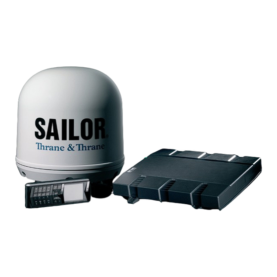
Chapter 1 System units Introduction The basic system consists of three units: The terminal, the antenna and the IP handset with cradle. The SAILOR 150 FleetBroadband terminal only works with a SAILOR 150 FleetBroadband Note antenna. SAILOR 150 FleetBroadband terminal ®... -
Page 10: Sailor ® 150 Fleetbroadband Antenna
Chapter 1: System units SAILOR 150 FleetBroadband antenna ® The SAILOR 150 FleetBroadband antenna is a BGAN mechanical tracking antenna. All communication between the antenna and terminal passes through a single coaxial cable. The antenna unit is protected by a thermo-plastic radome. TT-98-129218-A... -
Page 11: Thrane Ip Handset & Cradle
Besides the normal functions of an IP handset, the Thrane IP handset also provides a user interface for the SAILOR FleetBroadband system. The IP handset connects to the LAN interface of the terminal, and is power supplied with Power over Ethernet (PoE) through the LAN interface. -
Page 12: Chapter 2 Installing The System
Chapter 2 Installing the system Unpacking Unpack your SAILOR FleetBroadband system and check that the following items are present: • TT-3739A SAILOR 150 FleetBroadband terminal • TT-3050C SAILOR 150 FleetBroadband antenna • TT-3670A Thrane IP Handset & Cradle, wired •... -
Page 13: Placing The Antenna
20 m 104 cm Radiation hazard The SAILOR 150 FleetBroadband antenna radiates 16.1 dBW EIRP. This translates to a minimum safety distance of 0.6 m from the antenna while it is transmitting, based on a radiation level of 10 mW/cm... - Page 14 (including other Inmarsat based systems), because they may compromise the antenna performance. RF emission from radars might actually damage the antenna. The SAILOR FleetBroadband antenna itself may also interfere with other radio systems. Especially other Inmarsat systems and GPS receivers with poor frequency discrimination are vulnerable to the radiation generated by the SAILOR FleetBroadband antennas.
- Page 15 Even at distances greater than “d min.” in the previous section the radar might still be able to degrade the performance of the SAILOR FleetBroadband system. The presence of one or more X-band radars within a radius up to 100 m could cause a minor degradation of the signal-to-noise ratio during high speed and data calls.
- Page 16 Chapter 2: Installing the system The presences of S-band radar(s) are unlikely to cause any performance degradation – as long as the minimum distances (d min.) listed in the previous section are applied. It is strongly recommended that interference free operation is verified experimentally before the installation is finalized.
- Page 17 Antenna mast mounting Mast mount kit: The top of the SAILOR 150 FleetBroadband antenna mast should be fitted with the dedicated mounting kit available from Thrane & Thrane. Assemble the mast mount kit according to the assembly instruction included with the kit.
- Page 18 Also mount vibration isolators between the flange and the radome. For SAILOR 150 FleetBroadband, the vibration isolators are included in the Mast mount kit. Stays and rigid masts can still not prevent vertical vibration if the mast is attached to a Note deck plate that is not rigid.
- Page 19 Chapter 2: Installing the system Antenna mast length The below table shows the values for a SAILOR 150 FleetBroadband antenna mast without stays or wires. Note that these values are only guidelines - always consider the environment and characteristics of the ship before deciding on the mast dimensions.
-
Page 20: Installing The Antenna
The maximum allowed RF-loss in the antenna cable is 20 dB at 1660 MHz. This is to ensure the performance of the system. Recommended antenna cables The table below shows recommended cable types and maximum cable lengths for SAILOR 150 FleetBroadband. Cable Type Absolute maximum length G02232-D... - Page 21 Chapter 2: Installing the system • Antenna cable modem-attenuation at 54 MHz: max. 4 dB. Antenna cable modem-attenuation at 36 MHz: max. 3 dB. Antenna cable loop DC-resistance max: 1 . • Also ensure that the specified minimum bending radius is respected. If this is not the case, the loss in the cable will increase.
-
Page 22: Mounting The Antenna
Make sure the antenna has line of sight to the satellites. When the antenna is mounted directly on the hull, it may be difficult to obtain line of sight, especially down to -60°, which is the maximum rotation angle (pitch and roll) for the SAILOR 150 FleetBroadband antenna. Use M6 bolts for mounting the antenna. -
Page 23: Placing The Terminal
Chapter 2: Installing the system Placing the terminal Where to place the terminal Temperature conditions The terminal must be placed in a ventilated area with free space around all sides of the unit, except the bottom side. Ambient temperature range is –25°C to +55°C. If the terminal is installed in a location where the ambient temperature may exceed 50°C, we recommend placing the terminal where unintentional contact is avoided. -
Page 24: Installing The Terminal
Chapter 2: Installing the system Installing the terminal Grounding the terminal Antenna cable The antenna is connected to the terminal by means of a coax cable with a TNC connector at both ends. For information on antenna grounding, see Antenna grounding on page 12. Ground stud To ensure that the terminal is grounded –... - Page 25 Chapter 2: Installing the system Mounting the Basic cable support The Basic cable support is available from Thrane & Thrane. When mounted on the terminal the Basic cable support offers a number of holders to which you can secure the cables from the terminal, using cable strips. To mount the Basic cable support, do as follows: Remove the two rubber washers from the bottom of the terminal at the connector panel end.
- Page 26 Chapter 2: Installing the system Installing the terminal on a bulkhead Terminal with no cable support Do as follows to mount the terminal on a bulkhead: Insert four screws through the holes in the mounting bracket and into the mounting surface. If the mounting surface is used for grounding, make sure that you have a good electrical connection to the surface.
-
Page 27: Chapter 3 Connecting Power
Chapter 3 Connecting power Power source There are different options for the power supply: • The 24 V DC ship supply provides power for the terminal. • A 12 V DC supply provides power for the terminal. Note that the maximum allowed source impedance is much lower for a 12 V DC supply than for a 24 V DC supply. - Page 28 Chapter 3: Connecting power Power cable recommendations Overview The terminal is delivered with a power cable, which can be extended according to the recommendations in this section. • When extending the power cable, positive and negative supply wires must be installed closely together side by side to keep cable inductance low.
- Page 29 Chapter 3: Connecting power Calculating the maximum power cable extension For 24 V DC operation, the total impedance must be max. 500 m, including the source impedance in the ship installation. For 12 V DC operation, the total impedance must be max. 85 m, including the source impedance in the ship installation.
-
Page 30: Connecting Power
• Connect the ignition pins in the I/O connector to the ignition of your vessel. For further information, see Connecting to the ignition on page 22. For information on pin-out, see DC power input on page 26. For specifications of the DC input on the terminal, see SAILOR 150 FleetBroadband terminal on ®... - Page 31 Chapter 3: Connecting power To implement the ignition function, connect the appropriate pin in the I/O connector to the ignition key switch: • Active high (default): Connect pin 5 to Ground. Connect pin 8 to “high” (10.5-32 V DC) when the ignition is on.
-
Page 32: Chapter 4 Hardware Interfaces
Chapter 4 Hardware interfaces The connector panel The connector panel is placed at one end of the terminal and has the following connectors: • 1 Antenna connector (TNC) • 1 Phone connector • 2 LAN connectors with Power over Ethernet (PoE) •... -
Page 33: Antenna Interface On Terminal
Overview The antenna interface on the terminal connects to the TT-3050C antenna in the SAILOR 150 FleetBroadband system. The antenna connector on the terminal is a TNC female connector placed in the connector panel. For information on cables and how to install and connect the antenna, see Installing the antenna on page 12. -
Page 34: Dc Power Input
Chapter 4: Hardware interfaces DC power input Overview The DC power input for the terminal is a 10.5 - 32 V DC; 14 - 5.5 A input with a remote on/off function. The input is protected against reverse polarity. The power connector is a D-sub connector placed in the connector panel. For information on power recommendations and how to connect, see Connecting power on page 19. -
Page 35: Ground Stud
Chapter 4: Hardware interfaces Ground stud The terminal has a ground stud with a wing nut. The ground stud is located in the connector panel and is used for grounding the terminal. For information on how to ensure proper grounding of the terminal, see Grounding the terminal on page 16 and Grounding and RF protection on page 55. -
Page 36: Analog Phone Interface
Chapter 4: Hardware interfaces Analog Phone interface Overview The terminal has one RJ-11 port, which can be used for connection of an analog phone. Pin-out The Phone connector is an RJ-11, 6/4 female connector. The table and figure below show the connector outline and pin assignments. -
Page 37: Lan Interface
Chapter 4: Hardware interfaces LAN interface Overview The terminal has two Ethernet LAN ports with Power over Ethernet (PoE). The Ethernet ports are standard IEEE 802.3 af ports using RJ-45 connectors. Power over Ethernet (PoE) One power supply powers both interfaces with a floating 48 V DC supply (44 - 57 V DC). -
Page 38: Connecting The Thrane Ip Handset
Chapter 4: Hardware interfaces Pin-out The figure and table below show the connector outline and pin assignments. RJ-45 female connector Pin function number TxD+ input (positive PoE) TxD-input (positive PoE) RxD+ output (negative PoE) not connected not connected RxD- output (negative PoE) not connected not connected... -
Page 39: Discrete I/O Interface
Chapter 4: Hardware interfaces Discrete I/O interface Overview The terminal has an I/O connector with 5 configurable inputs/outputs. The connector is a WieCon Type 8513S connector. A mating I/O connector is included in the delivery. Pin-out The figure and table below show the connector outline and pin assignments. WieCon Type 8513S connector Pin number Connection... - Page 40 50 mA. Pin 7 can be used as power supply to a relay, ringer or similar. For information on how to configure the I/O pins, see the user manual for the SAILOR 150 FleetBroadband system. TT-98-129218-A Discrete I/O interface...
-
Page 41: Chapter 5 Starting Up The System
Chapter 5 Starting up the system Using the SIM card Inserting the SIM card The SIM card is provided by your Airtime Provider. Insert the SIM card as follows: Open the SIM cover in the left side of the connector panel. 2. - Page 42 However, if you have an administrator user name and password, you can upload software using the web interface without having a SIM card. For further information, see the user manual for the SAILOR 150 FleetBroadband system. Remove the SIM card as follows: Open the SIM cover in the left side of the connector panel.
-
Page 43: Powering The System
Connecting to the ignition on page 22. You must set up the ignition function in the web interface. For further information, see the user manual for the SAILOR FleetBroadband system. In some cases, the system may reboot after power-on because Note of the high start-up current. - Page 44 Chapter 5: Starting up the system Switching the terminal off To switch off the terminal, change the position of the power switch again. Wait at least 5 seconds after power off, before trying to power Note on the system again. To switch off using the Ignition function, leave the On/Off switch in the connector panel in the position On and turn off the ignition.
-
Page 45: Entering The Sim Pin For The Terminal
Chapter 5: Starting up the system Entering the SIM PIN for the terminal Overview If your SIM card requires a PIN, you have to enter a PIN to use the system. You can enter the PIN using a standard phone, the IP handset or the web interface. For information on how to connect the handset or computer you are going to use, refer to the user manual. - Page 46 Chapter 5: Starting up the system IP handset: After having entered the user name and password for the terminal you have 3 attempts to enter the terminal PIN, before you are asked to enter the PUK (Pin Unblocking Key). The PUK is supplied with your terminal SIM card.
-
Page 47: Operating The System
Operating the system General use The user manual for the SAILOR FleetBroadband system describes general use of the system and goes through all the functions of the web interface. It also contains a brief description of how to use the Thrane IP Handset with the terminal. -
Page 48: Chapter 6 Troubleshooting
Chapter 6 Troubleshooting Reset button How to access the Reset button The terminal has a Reset button placed next to the SIM slot behind the SIM cover. The functions of this button is described in the next section. To press the Reset button, use a pointed device. TT-98-129218-A Reset button... - Page 49 Chapter 6: Troubleshooting Functions of the Reset button The Reset button on the terminal has the following functions: Action Function With the terminal running, The terminal IP address and IP netmask are temporarily set to press the Reset button the default value (default IP address: 192.168.0.1). normally.
-
Page 50: Status Signaling
Chapter 6: Troubleshooting Status signaling Overview The SAILOR FleetBroadband system uses event messages and a light indicator for Power to display the status of the system. Power indicator The Power indicator is placed above the SIM slot in the connector panel. -
Page 51: Logging Of Events
The log includes the time of the occurrence, a short description, location of the error etc. This information can help troubleshooting errors in the system. You can see the event log in the web interface. For further information on the web interface, see the user manual for the SAILOR 150 FleetBroadband system. TT-98-129218-A Logging of events... -
Page 52: Appendix A Part Numbers
Appendix A Part numbers System units TT-3744A SAILOR 150 FleetBroadband system ® Item Part number SAILOR 150 FleetBroadband antenna 403050C SAILOR 150 FleetBroadband terminal 403739A TT-3670A Thrane IP Handset & Cradle, wired Item Part number Thrane IP Handset, wired 403672A... -
Page 53: Overview
Appendix B Technical specifications Overview This chapter contains specifications for the SAILOR 150 FleetBroadband system including the terminal and antenna. For specifications and outline drawings for the Thrane IP Note Handset, refer to the manual for the IP handset. SAILOR 150 FleetBroadband antenna ®... - Page 54 5 to 20 Hz: 0.05 g 20 to 150 Hz: -3 dB/octave Vibration, life test At least 1.7 g rms for 2 hours pr. axis. Spectrum: 5 to 20 Hz: 0.05 g2/Hz, 20 to 150 Hz: -3 dB/octave TT-98-129218-A SAILOR 150 FleetBroadband antenna ®...
- Page 55 Pitch: 15°, period 3 sec., 0.6 g tangential Yaw: 10°, period 5 sec., 0.3 g tangential Surge: 0.5 g Sway: 0.5 g Heave: 0.7 g Turning rate: 36°/s; 12°/s Headway: 22 m/s (42 knots) TT-98-129218-A SAILOR 150 FleetBroadband antenna ®...
- Page 56 Appendix B: Technical specifications Antenna outline dimensions Weight: 3.94 kg (8.7 lbs) Dimensions are in mm TT-98-129218-A SAILOR 150 FleetBroadband antenna ®...
-
Page 57: Minimum Distance To Transmitters
Appendix B: Technical specifications Minimum distance to transmitters. The table below shows the minimum recommended distance to transmitters in the frequency range below 1000 MHz. Recommended distance to SAILOR FleetBroadband antenna. TT-98-129218-A Minimum distance to transmitters. -
Page 58: Sailor ® 150 Fleetbroadband Terminal
Appendix B: Technical specifications SAILOR 150 FleetBroadband terminal ® General specifications Item Specification Weight SAILOR 150 FleetBroadband terminal: 2.2 kg (4.9 lbs) Dimensions 231 mm x 278 mm x 41 m (9.1” x 10.9” x 1.6”) Global services Voice 4 kbps AMBE+2 Data... - Page 59 Ignition function, off: max. 15 mA Remote on/off in DC connector, off: max. 2 mA Ambient Operational: -25° to +55°C temperature Storage: -40° to +80°C Relative Humidity 95% non-condensing at +40°C Equipment Protected from the weather - IEC-60945 category TT-98-129218-A SAILOR 150 FleetBroadband terminal ®...
- Page 60 Appendix B: Technical specifications Outline dimensions, SAILOR 150 FleetBroadband terminal ® Connector panel, top view and end view. TT-98-129218-A SAILOR 150 FleetBroadband terminal ®...
- Page 61 Appendix B: Technical specifications Side view and bottom view. Weight: 2.2 kg. Dimensions are in mm. TT-98-129218-A SAILOR 150 FleetBroadband terminal ®...
-
Page 62: Measuring The Ship Source Impedance
Appendix B: Technical specifications Measuring the ship source impedance Select a power outlet from the ship 24 V DC or 12 V DC system, and measure the source impedance of the ship installation as described below. Measure the voltage without load (R.var disconnected). 2. -
Page 63: Appendix C Grounding And Rf Protection
Appendix C Grounding and RF protection Why is grounding required? Reasons for grounding Grounding the SAILOR FleetBroadband system is required for two reasons: • Safety: Lightning protection of persons and equipment. • Protection: ESD (ElectroStatic Discharge) protection of equipment. Safety First of all grounding of the system is required for safety reasons. -
Page 64: About Marine Dc Systems
Appendix C: Grounding and RF protection About marine DC systems Wiring systems Two basic wiring topologies are used for marine DC system grounding: Two-Wire Return System and One Pole Grounded Return System. Two-wire Return System This configuration implies that no part of the circuit, in particular the battery negative, is connected to any ground potential or equipment. - Page 65 Appendix C: Grounding and RF protection One Pole Grounded Return System This configuration implies that the battery negative is bonded to a ground potential, typically at the engine negative terminal. This is done in order to polarize the DC electrical system. BATTERY BATTERY STARTER...
-
Page 66: About Marine Grounding
Appendix C: Grounding and RF protection About marine grounding There is great confusion about the different ground terms used when dealing with marine electrical installations. The various terms are listed below for reference. Term Definition DC Negative Actually not a ground but a current-carrying conductor which carries the same current that flows in the positive conductor. -
Page 67: Grounding Recommendations
Appendix C: Grounding and RF protection Grounding Recommendations Grounding the terminal The terminal should be grounded to the ship/hull by means of a short antenna cable and a grounding kit. Further, the terminal must be grounded at its grounding stud in order to ensure proper grounding if the short antenna cable is disconnected. -
Page 68: Alternative Grounding For Steel Hulls
Appendix C: Grounding and RF protection Alternative grounding for steel hulls The following guidelines assume a two-wire, isolated grounding arrangement; that is no part of the circuit, in particular the battery negative, is connected to any ground potential or equipment. Grounding the terminal The terminal must be grounded to the ship with the short antenna cable and the Grounding kit (accessories). - Page 69 Appendix C: Grounding and RF protection Terminal grounded at a dedicated RF ground (alternative) In this case the antenna is grounded with a separate ground cable. The ground cable must be routed parallel and close to the shielded coax cable connecting the antenna to the terminal grounding kit.
-
Page 70: Alternative Grounding For Aluminum Hulls
Appendix C: Grounding and RF protection Alternative grounding for aluminum hulls The following guidelines assume a two-wire, isolated grounding arrangement; that is no part of the circuit, in particular the battery negative, is connected to any ground potential or equipment. Grounding the terminal The terminal must be grounded with the short antenna cable and the Grounding kit. -
Page 71: Alternative Grounding For Fiberglass Hulls
Appendix C: Grounding and RF protection Alternative grounding for fiberglass hulls Grounding the terminal The terminal must be grounded with the short antenna cable and the Grounding kit (accessories). Further, the terminal must be grounded at its grounding stud in order to ensure a proper grounding if the short antenna cable is disconnected. -
Page 72: Alternative Grounding For Timber Hulls
Appendix C: Grounding and RF protection Alternative grounding for timber hulls Grounding the terminal The terminal must be grounded with the short antenna cable and the Grounding kit (accessories). Further, the terminal must be grounded at its grounding stud in order to ensure a proper grounding if the short antenna cable is disconnected. -
Page 73: Separate Ground Cable
Appendix C: Grounding and RF protection Separate ground cable Ground cable - construction When dealing with electrical installations in a marine environment, all wiring must be done with double insulated, tinned, high quality and if exposed also UV resistant cables. This shall also apply to the separate ground cable mentioned in the previous paragraphs. - Page 74 Appendix C: Grounding and RF protection In the below drawing, vibration isolators are mounted. Vibration isolator Plain washer (stainless steel) Ground cable Serrated washer (stainless steel) Plain washer (stainless steel) Spring washer (stainless steel) At the other end, connect the ground cable at the terminal grounding kit. TT-98-129218-A Separate ground cable...
- Page 75 Appendix C: Grounding and RF protection Isolation of the antenna from the mounting base In cases where the antenna is to be isolated from the mounting base, shoulder bushes and washers (accessories) must be used as illustrated below. Please note that the isolation has to be implemented on all four mounting bolts (including the bolt securing the ground cable).
-
Page 76: Rf Interference
Interference induced from nearby RF transmitters might cause system failures and in extreme cases permanent damage to the SAILOR FleetBroadband equipment. If there are problems with interference from HF transmitters, it is advisable to mount ferrite clamps on the coax cable in order to provide suppression of induced RF. -
Page 77: Glossary
Glossary Glossary American Wire Gauge. A means of specifying wire diameters. Compact Disc Continuous Monitoring DTMF Dual Tone Multi Frequency. The keypad signaling technology that generates two distinct tones when each key is pressed. This system allows navigation of voice menus and other advanced calling services. - Page 78 Glossary Internet Protocol. The method or protocol by which data is sent from one computer to another on the Internet. Local Area Network PAST Person Activated Self Test. A test similar to the POST test, but activated by the user. The PAST causes the system to reset.
- Page 79 Glossary TFTP Trivial File Transfer Protocol. A very simple file transfer protocol, with the functionality of a very basic form of FTP. Since it is so simple, it is easy to implement in a very small amount of memory. Threaded Neill-Concelman. A type of RF connector used for terminating coaxial cables. The TNC connector is a threaded version of the BNC connector.
-
Page 80: Index
Index Index alarms electrostatic discharge aluminum hulls recommendations grounding error messages analog phone interface events antenna logging cables dimensions grounding grounding recommendations fiberglass hulls installation location grounding installing interference isolation from mounting base mast design obstructions GPS receiver outline distance from antenna radiation grounding access... - Page 81 Index interfaces on terminal placing the antenna analog phone interface placing the terminal antenna DC power input pole mount discrete I/O power cable overview cable extension interference connecting connecting remote on/off IP handset sources connecting switching on entering PIN with using remote on/off short description power input on terminal...
- Page 82 Index technical specifications terminal temperature terminal cable support grounding grounding recommendations installation location installing introduction outline and dimensions timber hulls grounding tools for operation troubleshooting typography used in this manual user interfaces TT-98-129218-A...
Need help?
Do you have a question about the 150 FleetBroadband and is the answer not in the manual?
Questions and answers