Motoman XRC 2001 Operator's Manual
For spot welding
Hide thumbs
Also See for XRC 2001:
- Concurrent i/o and parameter manual (321 pages) ,
- Manual (38 pages) ,
- Instructions manual (30 pages)
Table of Contents
Advertisement
Quick Links
See also:
Manual
Advertisement
Table of Contents

Related Manuals for Motoman XRC 2001


Summary of Contents for Motoman XRC 2001
- Page 1 Motoman XRC 2001 Controller Operator’s Manual for Spot Welding Part Number: 142101-1 Release Date: November 28, 2006 Document Status: Final Motoman, Incorporated 805 Liberty Lane West Carrollton, OH 45449 TEL: (937) 847-6200 FAX: (937) 847-6277 24-Hour Service Hotline: (937) 847-3200...
- Page 2 COMPLETE OUR ONLINE SURVEY Motoman is committed to total customer satisfaction! Please give us your feedback on the technical manuals you received with your Motoman robotic solution. To participate, go to the following website: http://www.motoman.com/pubs/survey.php The information contained within this document is the proprietary property of Motoman, Inc., and may not be copied, reproduced or transmitted to other parties without the expressed written authorization of Motoman, Inc.
- Page 3 TABLE OF CONTENTS Section Page INTRODUCTION .......................... 1-1 SAFETY ............................2-1 XRC OPERATOR’S MANUAL FOR BEGINNERS ................3-1 XRC OPERATOR’S MANUAL FOR SPOT WELDING..............4-1 MOTOMAN XRC Operator’s Manual for Spot Welding...
-
Page 4: Xrc Operator's Manual For Spot Welding
NOTES XRC Operator’s Manual for Spot Welding MOTOMAN... -
Page 5: Safety
XRC Inform II manual (P/N 142971-1). Please contact your salesman directly, or the Motoman service staff at (937) 847-3200, to order the XRC Inform II manual. This manual is organized as follows: SECTION 1 –... - Page 6 INTRODUCTION Customer Service Information If you are in need of technical assistance, contact the Motoman service staff at (937) 847-3200. Please have the following information ready before you call: • Robot Type (UP6, UP130, UP165, etc.) • Application Type (welding, handling, etc.) •...
- Page 7 We recommend that all personnel who intend to operate, program, repair, or use the robot system be trained in an approved Motoman training course and become familiar with the proper operation of the system. This safety section addresses the following: •...
- Page 8 NOTE: Information appearing in a NOTE caption provides additional information which is helpful in understanding the item being explained. XRC Operator’s Manual for Spot Welding MOTOMAN...
- Page 9 Safety fences and barriers • Light curtains • Door interlocks • Safety mats • Floor markings • Warning lights Check all safety equipment frequently for proper operation. Repair or replace any non-functioning safety equipment immediately. MOTOMAN XRC Operator’s Manual for Spot Welding...
- Page 10 Do not make any modifications to PART 1. Making any changes without the written permission of Motoman will VOID YOUR WARRANTY! • Some operations require standard passwords and some require special passwords.
- Page 11 This includes controller parameters, ladder parts 1 and 2, and I/O (Input and Output) modifications. Check and test all changes at slow speed. MOTOMAN XRC Operator’s Manual for Spot Welding...
- Page 12 (Input and Output) modifications. Check and test all changes at slow speed. • Improper connections can damage the robot. All connections must be made within the standard voltage and current ratings of the robot I/O (Inputs and Outputs). XRC Operator’s Manual for Spot Welding MOTOMAN...
-
Page 13: Xrc Operator's Manual For Beginners
FOR BEGINNERS Upon receipt of the product and prior to initial operation, read these instructions thoroughly, and retain for future reference. MOTOMAN INSTRUCTIONS MOTOMAN SETUP MANUAL MOTOMAN-¨¨¨ INSTRUCTIONS YASNAC XRC INSTRUCTIONS YASNAC XRC OPERATOR’S MANUAL YASNAC XRC OPERATOR’S MANUAL FOR BEGINNERS The YASNAC XRC operator’s manuals above correspond to specific usage. - Page 14 M A N D A T O R Y • This manual explains the various components of the YASNAC XRC sys- tem and general operations. Read this manual carefully and be sure to understand its contents before handling the YASNAC XRC. •...
- Page 15 NOTES FOR SAFE OPERATION Read this manual carefully before installation, operation, maintenance, or inspection of the YASNAC XRC. In this manual, the Notes for Safe Operation are classified as “WARNING”, “CAUTION”, “MANDATORY”, or ”PROHIBITED”. Indicates a potentially hazardous situation which, if not avoided, WARNING could result in death or serious injury to personnel.
- Page 16 WARNING • Before operating the manipulator, check that servo power is turned off when the emergency stop buttons on the playback panel or program- ming pendant are pressed. When the servo power is turned off, the SERVO ON READY lamp on the playback panel and the SERVO ON LED on the programming pendant are turned off.
- Page 17 • Read and understand the Explanation of the Alarm Display in the Setup Manual before operating the manipulator. Definition of Terms Used Often in This Manual The MOTOMAN manipulator is the YASKAWA industrial robot product. The manipulator usually consists of the controller, the playback panel, the programming pen- dant, and supply cables.
- Page 18 Descriptions of the programming pendant and playback panel keys, buttons, and displays are shown as follows: Equipment Manual Designation Programming Character Keys The keys which have characters printed on them are Pendant denoted with [ ]. ex. [ENTER] Symbol Keys The keys which have a symbol printed on them are not denoted with [ ] but depicted with a small picture.
-
Page 19: Table Of Contents
INTRODUCTION 1.1 XRC Overview ..........1-1 1.2 Button Descriptions . - Page 20 PLAYBACK 4.1 Preparation Prior to Playback ......4-1 4.2 Playback ........... 4-1 ARC WELDING 5.1 Example Job .
- Page 21 GENERAL PURPOSE 7.1 Example Job ..........7-1 7.2 Teaching Procedure .
-
Page 23: Introduction
The playback panel can be found mounted on the cabinet door of the controller. Find information for setup, installation, and connection of the XRC system by referring to the “MOTOMAN Setup Manual”. -
Page 24: Button Descriptions
1.2 Button Descriptions Button Descriptions Playback panel buttons are enclosed in brackets throughout this manual. T E A C H [TEACH] on the playback panel... -
Page 25: Programming Pendant
1.3 Programming Pendant Programming Pendant Programming Pendant... -
Page 26: Key Descriptions
1.4 Key Descriptions Key Descriptions Named Keys The keys which have a name on them are denoted with [ ]. is shown as [ENTER] and E N T E R T E A C H is shown as [TEACH LOCK]. L O C K The number keys have additional functions along with their number values. -
Page 27: Screen Descriptions
1.5 Screen Descriptions Screen Descriptions Menu items shown in the programming pendant display are denoted with { }. DISPLAY E D I T UTILITY In the case of the above menu, each item is shown as {JOB}, {EDIT}, {DISPLAY}, and {UTIL- ITY}. -
Page 28: Operation Sequence
1.6 Operation Sequence Operation Sequence The following basic sequence is used to operate the manipulator. 1. Turn on the XRC controller. 2. Teach a job on the robot. 3. Replay the job on the manipulator. (called “playback”) 4. When finished, turn off the power. Be sure to follow the proper shutdown sequence as described in Section 6. -
Page 29: Turning The Power On
2.1 Turning On the Main Power 2 TURNING THE POWER ON When turning on the power, always turn on the main power supply first and then the servo power supply. Ensure that the area around the manipulator is safe before turning on the power. -
Page 30: Turning On The Servo Power
2.2 Turning on the Servo Power Turning on the Servo Power 2.2.1 During Play Mode 1. When the safety guard is closed, press [SERVO ON READY] S E R V O O N R E A D Y on the playback panel to turn on the servo power supply. This button lights. - Page 31 2.2 Turning on the Servo Power When using the playback panel, programming pendant, or external signal to perform emer- N OT E gency stop, the servo power on operation from the deadman switch is cancelled. When turning the power back on, follow the previously listed instructions.
- Page 32 2.2 Turning on the Servo Power...
-
Page 33: Teaching
3.1 Manipulator Motion 3 TEACHING Manipulator Motion The robot is generally operated using two types of coordinates: joint coordinates and rectan- gular coordinates. Press the axis operation keys on the programming pendant to move each axis of the manipulator. 3.1.1 Joint Coordinates... - Page 34 3.1 Manipulator Motion...
-
Page 35: Rectangular Coordinates
3.1 Manipulator Motion 3.1.2 Rectangular Coordinates (This figure shows direction only (not position) of rectangular coordinates.) -
Page 36: Move Instructions And Steps
3.1 Manipulator Motion 3.1.3 Move Instructions and Steps The manipulator uses job instructions to move and execute playback. This is called a move instruction. The destination position, the interpolation method, the play speed, etc. are regis- tered in the move instruction. The reason it is called a move instruction is that the main instruction begins with “MOV”... -
Page 37: Teaching
3.2 Teaching Teaching 3.2.1 Preparation Before Teaching Perform the following tasks before starting to teach. • Enable the operation of the playback panel. • Set the operation mode to teach mode. • Set the teach lock. • Enter the job name. 1. - Page 38 3.2 Teaching 5. After the new job display is shown, press [SELECT]. S E L E C T J O B EDIT D I S P L A Y UTILITY N E W J O B C R E A T E JOB NAME ¬¬¬¬¬¬¬¬...
- Page 39 3.2 Teaching 9. Move the cursor to “EXEC” and press [SELECT]. The job “TEST” is registered in the XRC memory and the job is dis- S E L E C T played. The NOP and END instructions are automatically reg- istered.
-
Page 40: Teaching
3.2 Teaching 3.2.2 Teaching Teaching a Job A job is a work program that describes the tasks that the manipulator will execute. Jobs are created using a robot programming language called INFORM II. The following example will instruct you how to teach the manipulator all of the steps from Point A to Point B of the following workpiece. -
Page 41: Step 1 -- Start Position
3.2 Teaching Step 1 -- Start Position Always be sure the manipulator is in a safe work area before operation. 1. Grip the deadman switch and the servo power will turn on. The manipulator can then be operated. 2. Move the manipulator to the desired position using the axis operation keys. -
Page 42: Step 2 -- Near The Work Start Location
3.2 Teaching Step 2 -- Near the Work Start Location Define the manipulator work pose. 1. Move the manipulator to the working position using the axis operation keys. 2. Press [ENTER]. Step 2 (Line 0002) is registered. E N T E R 0000 N O P 0001 MOVJ V J=50.00 0002... -
Page 43: Step 4 -- Work End Position
3.2 Teaching 4. The input buffer line is displayed. Move the cursor to the right to VJ=*.**, which shows the speed. While pressing [SHIFT] simultaneously, move the cursor up and down (to higher and lower play speeds) until the desired speed is specified. S H I F T Set the speed 12.50%. -
Page 44: Step 5 -- Position Away From Workpiece And Fixture
3.2 Teaching 5. Press [ENTER]. Step 4 (Line 0004) is registered. E N T E R 0000 N O P 0 0 0 1 M O V J VJ=50.00 0 0 0 2 M O V J V J =50.00 0 0 0 3 M O V J V J = 1 2 . -
Page 45: Step 6 -- Near The Start Position
3.2 Teaching 5. The input buffer line is displayed. Move the cursor to the right to V=*.**, which shows the speed. While pressing [SHIFT] simultaneously, move the cursor up and down (to higher and lower play speeds) until the desired speed is specified. S H I F T Set the speed to 50%. -
Page 46: Ensuring The First And Last Step Are Identical
3.2 Teaching Ensuring the First and Last Step are Identical The manipulator has stopped at Step 6, which should be very close to Step1. It is possible to move directly from the welding end position of Step 5 to Step1, so the manipu- lator can begin the next welding job quickly and efficiently. -
Page 47: Correcting A Job
3.2 Teaching 2. Change to medium speed by pressing [FST] or [SLW]. F S T J O B E D I T DISPLAY UTILITY MAN SPD S L W J O B C O N T E N T 3. Press [FWD] to confirm each step executed by the manipula- tor. -
Page 48: Change The Position Data
3.2 Teaching Change the Position Data Change the position registered in Step 2. 1. Move the manipulator to Step 2 (Line 0002) by pressing [FWD]. F W D 2. Move the manipulator to the modified position with the axis operation keys. 3. -
Page 49: Delete A Step
3.2 Teaching 3. Press [INSERT]. I N S E R T 4. Press [ENTER]. The step is added. When a step is added, the numbering is automatically adjusted to count the new step. E N T E R 0 0 0 4 M O V L V = 1 3 8 0 0 0 5 M O V J V J = 5 0 . -
Page 50: Changing The Speed Between Steps
3.2 Teaching When “Error 2070: Set Robot Exactly to Taught Position” Occurs S U P P L E - M E N T When the operator presses [ENTER] during the previous operation, an error can occur in some cases. The error occurs because the manipulator has not been moved exactly to the taught position. -
Page 51: Playback
4.1 Preparation Prior to Playback 4 PLAYBACK Preparation Prior to Playback Before executing manipulator playback, release the teach lock. 1. Press [TEACH LOCK]. After pressing the button, be sure [TEACH LOCK] lights. T E A C H L O C K To run the program from the beginning of the job, perform the following operation. - Page 52 4.2 Playback...
-
Page 53: Arc Welding
5.1 Example Job 5 ARC WELDING Example Job The figure below shows an example of welding a workpiece with an explanation of each step. Example Job LINE INSTRUCTION EXPLANATION 0000 0001 MOVJ VJ=25.00 Moves manipulator to waiting position. (Step 1) 0002 MOVJ VJ=25.00 Moves manipulator near welding start position. -
Page 54: Operation Method
5.2 Teaching Procedure • Step 1 and 6, which are both the waiting position, are adjusted to a safe position where N OT E the robot does not collide with the workpiece and the fixture, etc. • Ensure that the length of the wire is the same during teaching and playback. The appro- priate wire length can be determined by using the inching procedure. -
Page 55: Step 4 -- Welding End Condition
5.2 Teaching Procedure 4. The input buffer line is displayed. Move the cursor to the right to VJ=*.**, which shows the speed. While pressing [SHIFT] simultaneously, move the cursor up and down (to higher and lower play speeds) until the desired speed is specified. S H I F T Set the speed 12.50%. -
Page 56: Setting Welding Conditions
5.3 Setting Welding Conditions 5. Press [ENTER]. Step 4 is registered. E N T E R 0000 N O P 0001 MOVJ VJ=25.00 0002 MOVJ VJ=25.00 0003 MOVJ VJ=12.50 0004 ARCON 0005 MOVL V=50 0006 END 6. Press [ARCOF]. ARCOF is displayed in the input buffer line. =>... -
Page 57: Setting Other Parameters
5.3 Setting Welding Conditions 2. Press [SELECT] if the “MENU” setting is “UNUSED” or “ASF#(%)” in the detail edit display. Select “AC=” in the selec- S E L E C T tion dialog. The detail edit display is shown as follows. D I S P L A Y J O B E D I T... -
Page 58: Welding Test
5.4 Welding Test Welding Test 5.4.1 Check Run Perform the check run in order to confirm that the teaching procedure was done correctly. The check run can be performed without performing actual work. This is possible because the work output instruction of the ARCON instruction is not executed. 1. -
Page 59: Welding Execution
5.4 Welding Test 5.4.2 Welding Execution Once the path has been determined, the welding is finally executed. If the check run is turned off, the ARCON and the ARCOF instructions are executed. 5.4.3 Adjustments for Welding Defects To adjust welding conditions after welding, look at the appearance of the welding bead. Welding Defect Reason for Occurrence Correction Method... - Page 60 5.4 Welding Test Welding Defect Reason for Occurrence Correction Method Undercut: • Excessive welding current • Lower the welding current and speed. Defect name for when the • Incorrect welding voltage Adjust the voltage. groove is not completely • Excessive welding speed filled along the toe of the •...
- Page 61 5.4 Welding Test Welding Defect Reason for Occurrence Correction Method Convex bead: • Welding current is too high • Lower the welding speed. Part of the fillet weld has a • Arc voltage is too low • Adjust the voltage. swelled bead surface.
- Page 62 5.4 Welding Test 5-10...
-
Page 63: Handling
6.1 Example Job 6 HANDLING Example Job The figure below shows an example of handling a workpiece. The job creating procedure is then explained. LINE INSTRUCTION EXPLANATION 0000 0001 MOVJ VJ=25.00 Move to waiting position (Step1) 0002 MOVJ VJ=25.00 Move near gripping position (before gripping) (Step2) 0003 MOVL V=100.0... -
Page 64: Usage Of Hand Instruction
6.2 Usage of HAND Instruction Usage of HAND Instruction 6.2.1 Function These instructions open and close the each of the hands mounted to the manipulator. They correspond to single-, double-, and triple solenoids. Up to four hands can be controlled by a single manipulator. -
Page 65: Teaching Procedure
6.3 Teaching Procedure ‚ ‚ ‚ ‚ Tool Number (1 to 4) Required ƒ ƒ ƒ ƒ Tool Output Status (ON/OFF) Required. Select ON or OFF „ „ „ „ Valve Simultaneous Control (ALL) Add to turn tool valves 1 and 2 ON or OFF simultaneously. Teaching Procedure 6.3.1 Teaching Points... -
Page 66: Step 3 -- Gripping Position
6.3 Teaching Procedure Step 3 -- Gripping Position Move the torch to the gripping position as in Step 2, and register the HAND instruction. 1. Change to medium speed by pressing [FST] or [SLW]. F S T Medium speed: is displayed in the status area. M A N S P D S L W D I S P L A Y... -
Page 67: Step 4 -- Near Gripping Position (After Gripping)
6.3 Teaching Procedure 9. The input buffer line is displayed. Move the cursor to the right to “T=1.00”, which shows the time. Set to 0.5s with the number keys. => TIMER T=0.50 Press [ENTER]. The TIMER instruction is registered. E N T E R Press [INFORM LIST] again. -
Page 68: Step 6 -- Near Release Position (Before Releasing)
6.3 Teaching Procedure Step 6 -- Near Release Position (before releasing) Define the pose of the release torch. 1. Specify the correct position with the axis operation keys for the manipulator to begin releasing the workpiece. It is neces- sary to choose a place in which the holding workpiece and the piling up workpiece do not interfere when the manipulator approaches the palette, and teach that position. -
Page 69: Step 8 -- Release Position
6.3 Teaching Procedure 3. Move the cursor to the line number and press [SELECT]. S E L E C T => M O V L V=11.0 4. The input buffer line is displayed. Move the cursor to the right to “V=11.0”, which shows the speed. Set to 100 mm/s with the number keys. - Page 70 6.3 Teaching Procedure 5. Press [ENTER]. Step 8 is registered. E N T E R 0000 N O P 0001 MOVJ VJ=25.00 0002 MOVJ VJ=25.00 0003 MOVL V=100.0 0004 HAND 1 ON 0005 TIMER T=0.50 0006 MOVL V=100.0 0007 MOVJ VJ=25.00 0008 MOVJ VJ=25.00 0009 MOVL V=100.0 0010...
-
Page 71: Step 9 -- Near Release Position (After Release)
6.4 Handling Test Step 9 -- Near Release Position (after release) Define the waiting positon. 1. Move the manipulator nearthe release position with the axis operation keys. It is necessary to choose a direction in which the tools and workpiece do not interfere, and teach that posi- tion. -
Page 72: Handling Execution
6.4 Handling Test 2. Select {UTILITY} and {SPECIAL RUN}. The special play dis- play is shown. D A T A UTILITY E D I T D I S P L A Y SPECIAL PLAY LOW SPEED START INVALID SPEED LIMIT INVALID DRY-RUN SPEED INVALID... -
Page 73: General Purpose
7.1 Example Job 7 GENERAL PURPOSE Example Job The figure below shows an example of cutting. The job creation procedure is then explained. LINE INSTRUCTION EXPLANATION 0000 0001 MOVJ VJ=25.00 Move to the waiting positon. (Step1) 0002 MOVJ VJ=25.00 Move near the cutting position. (Step2) 0003 MOVJ VJ=12.50... -
Page 74: Operation Procedure
7.2 Teaching Procedure Step 1, which is the waiting positon, is adjusted to a safe position where the robot will not N OT E collide with the workpiece and the tool. Confirm the cutting path with [FWD] and [BWD] after teaching. 7.2.2 Operation Procedure Step 2 -- Near cutting position... -
Page 75: Step 4 -- Cutting End Position
7.2 Teaching Procedure 5. Press [ENTER]. Step 3 is registered. E N T E R 0000 N O P 0001 MOVJ VJ=25.00 0002 MOVJ VJ=25.00 0003 MOVJ VJ=12.50 0004 END 6. Press [TOOLON]. “TOOLON” is displayed in the input buffer line. -
Page 76: Cutting Test
7.3 Cutting Test 6. Press [TOOLOF]. “TOOLOF” is displayed in the input buffer line. => T O O L O F Press [ENTER]. The TOOLOF instruction is registered. E N T E R Cutting Test 7.3.1 Speed Limitation Drive The speed limitation drive is executed to confirm the taught path. All the operations operate below the limitation speed during teach mode (250mm/s ususally) in the speed limitation drive. -
Page 77: Cutting Execution
7.3 Cutting Test 7.3.2 Cutting Execution Once the path has been determined, cutting is finally executed at actual speed. If the speed limitation drive is turned off, cutting is executed at the same speed as during teaching. - Page 78 7.3 Cutting Test...
-
Page 79: Spot Welding
8.1 Example Job 8 SPOT WELDING Example Job The figure below shows an example of the spot welding of a workpiece. The job content pro- cedure is then explained. LINE INSTRUCTION EXPLANATION 0001 NOP 0002 MOVJ VJ=25.00 Move to waiting position. (Step 1) 0003 MOVJ VJ=25.00 Move near welding start position. -
Page 80: Setting Welding Conditions
8.2 Setting Welding Conditions Setting Welding Conditions 8.2.1 Setting Spot Welding Gun Condition Files The following items are specified in the spot welding gun condition files. • GUN NO. (Initial:1) • GUN TYPE (Initial:SINGLE GUN) • WELDER NO. (Initial:1) • OPEN MONITOR (Initial:OFF) •... -
Page 81: Teaching Procedure
8.3 Teaching Procedure Large Current - Short Time Small Current - Long Time Board Thickness Pressurizing Pressurizing (mm) Time (cycle) Current (A) Time (cycle) Current (A) Power (kgf) Power (kgf) 8800 5600 13000 8000 17400 10000 (1cycle =16.7msec) Teaching Procedure 8.3.1 Teaching Procedure Items The teaching procedure is expained in Step2 (welding pose definition) and the welding proce-... -
Page 82: Step 3 -- Welding Start Position
8.3 Teaching Procedure Step 3 -- Welding Start Position Move the torch to the welding start location and register the SPOT instruction. 1. Change the speed to medium by pressing [HIGH] + [SLW]. F S T is displayed in status area. MAN SPD S L W EDIT... -
Page 83: Welding Test
8.4 Welding Test Welding Test 8.4.1 Check Run Execute the check run in order to confirm that the teaching procedure is done correctly. The check run can be conducted without actually performing work. This is because the work out- put instruction of the SPOT instruction is not executed. 1. - Page 84 8.4 Welding Test...
-
Page 85: Turning The Power Off
9.1 Turning the Servo Power Off (Emergency Stop) 9 TURNING THE POWER OFF Turning the Servo Power Off (Emergency Stop) When the emergency stop button is pressed, the servo power supply is turned off and the manipulator cannot be operated. The Emergency Stop emergency stop button is on both the programming pendant and Programming Pendant... - Page 86 9.2 Turning the Main Power Off...
- Page 88 BEIJING YASKAWA BEIKE AUTOMATION ENGINEERING CO.,LTD. 30 Xue Yuan Road, Haidian, B eijing P.R. China Post Code: 100083 Phone 86-10-6233-2782 Fax 86-10-6232-1536 SHOUGANG MOTOMAN ROBOT CO., LTD. 7,Yongchang-North Street, Beijing Economic Technological Investment & Development Area, Beijing 100076, P.R. China Phone 86-10-6788-0551...
- Page 89 FOR SPOT WELDING Upon receipt of the product and prior to initial operation, read these instructions thoroughly, and retain for future reference. MOTOMAN INSTRUCTIONS MOTOMAN SETUP MANUAL MOTOMAN-¨¨¨ INSTRUCTIONS YASNAC XRC INSTRUCTIONS YASNAC XRC OPERATOR’S MANUAL YASNAC XRC OPERATOR’S MANUAL for BEGINNERS The YASNAC XRC operator’s manuals above correspond to specific usage.
- Page 90 M A N D A T O R Y • This manual explains the various components of the YASNAC XRC sys- tem and general operations. Read this manual carefully and be sure to understand its contents before handling the YASNAC XRC. •...
- Page 91 NOTES FOR SAFE OPERATION Read this manual carefully before installation, operation, maintenance, or inspection of the YASNAC XRC. In this manual, the Notes for Safe Operation are classified as “WARNING”, “CAUTION”, “MANDATORY”,or ”PROHIBITED”. Indicates a potentially hazardous situation which, if not avoided, WARNING could result in death or serious injury to personnel.
- Page 92 WARNING • Before operating the manipulator, check that servo power is turned off when the emergency stop buttons on the playback panel or program- ming pendant are pressed. When the servo power is turned off, the SERVO ON READY lamp on the playback panel and the SERVO ON LED on the programming pendant are turned off.
- Page 93 • Read and understand the Explanation of the Alarm Display in the setup manual before operating the manipulator. Definition of Terms Used Often in This Manual The MOTOMAN manipulator is the YASKAWA industrial robot product. The manipulator usually consists of the controller, the playback panel, the programming pen- dant, and supply cables.
- Page 94 Descriptions of the programming pendant and playback panel keys, buttons, and displays are shown as follows: Equipment Manual Designation Programming Character Keys The keys which have characters printed on them are Pendant denoted with [ ]. ex. [ENTER] Symbol Keys The keys which have a symbol printed on them are not denoted with [ ] but depicted with a small picture.
- Page 95 An Introduction to XRC 1.1 Controller ...........1-1 1.2 Playback Panel .
- Page 96 2.6 Tool Coordinates ......... . . 2-9 2.6.1 Axis Motion .
- Page 97 3.4.6 Modifying Timer Instructions .......3-31 Deleting Timer Instructions ......3-31 Modifying Timer Instructions .
- Page 98 4.5.2 Playback from Reserved Start ......4-27 Start Operation........4-27 Checking Job Reservation Status .
- Page 99 5.3.4 Editing User Variables ........5-32 Displaying Byte, Integer, Double-Precision, and Real Type Variables .
- Page 100 6.3.2 Operating Methods ........6-22 Specifying the Conversion Items .
- Page 101 10.2 Registering Work Instructions ......10-3 10.2.1 GUNCL Instruction ........10-3 Additional items.
- Page 102 13.2.4 OPERATION MODE = 3 (FULL OPEN -> WELDING -> SHORT OPEN) ....13-7 Gun Motion Control (With C gun double stroke) (With X gun double stroke , cylinder type) ....13-7 Gun Motion Control (With X gun double stroke, mechanical stopper type) .
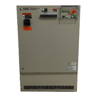
- Page 104 1.1 Controller 1 An Introduction to XRC Controller The main power switch is located on the front of the XRC controller. The playback panel is installed in the upper right corner of the cabinet door and the programming pendant hangs on a hook below the playback panel.
- Page 105 1.2 Playback Panel Playback Panel 1.2.1 Playback Panel Overview The playback panel is equipped with the buttons used to play back the manipulator. 1.2.2 Button Description Playback panel buttons are enclosed in brackets throughout this manual. T E A C H [TEACH] on the playback panel S T A R T [START] on the playback panel...
- Page 106 1.2 Playback Panel 1.2.3 Playback Panel Buttons Turns off the servo power. E M E R G E N C Y S T O P Enables the servo power ON. Use this button to turn servo power ON after and emergency stop or servo S E R V O O N overrun condition.
- Page 107 1.3 Programming Pendant Programming Pendant 1.3.1 Programming Pendant Overview The programming pendant is equipped with the keys and buttons used to conduct manipulator teaching operations and to edit jobs.
- Page 108 1.3 Programming Pendant 1.3.2 Key Description Character Keys The keys which have characters printed on them are denoted with [ ]. is shown as E N T E R [ENTER] and T E A C H is shown as [TEACH LOCK]. L O C K The number keys have additional functions along with their number values.
- Page 109 1.3 Programming Pendant 1.3.3 Programming Pendant Keys Turns off the servo power. E.STOP Button When the servo power is turned off, the SERVO ON LED on the program- ing pendant and the SERVO ON READY lamp will light. T U R N E .S T O P An emergency stop message is displayed on the screen.
- Page 110 1.3 Programming Pendant Moves the cursor between “Menu Area” and "General Pur- Area Key pose Display Area". Displays the next page. Page Key When [SHIFT] is pressed simultaneously with [PAGE], the previous page is displayed. Displays the content related to the current line. To display the content of a CALL job or condition file, move the cursor to the next line and press [DIRECT OPEN].
- Page 111 1.3 Programming Pendant Selects the motion type for playback operation. The selected motion type is shown in the status display area on the screen. Each time this key is pressed, the motion type changes in the following order: [MOTION TYPE] "MOVJ"à"...
- Page 112 1.3 Programming Pendant Deletes registered instructions and data. [DELETE] [DELETE] functions only when the key lamp is lit. D E L E T E Inserts new instructions or data. [INSERT] [INSERT] functions only when the key lamp is lit. I N S E R T Modifies taught position data, instructions, and data.
- Page 113 1.3 Programming Pendant 1.3.4 Programming Pendant Display The Four Display Areas The programming pendant display area is 40 columns by 12 lines. The display area is made up of three different sections. M E N U A R E A S T A T U S A R E A G E N E R A L D I S P L A Y A R E A H U M A N I N T E R F A C E D I S P L A Y A R E A...
- Page 114 1.3 Programming Pendant ‚ ‚ ‚ ‚ OPERATION CORDINATE SYSTEM Displays the selected coordinate system. : Link Coordinate : XYZ Coordinate : Cylinder Coordinate : Tool Coordinate : User Coordinate ƒ ƒ ƒ ƒ MANUAL SPEED Displays the selected speed. : Inching : Low Speed : Medium Speed...
- Page 115 1.3 Programming Pendant Human Interface Display Area The human interface display area is used for display information such as the instruction being input, data, and error messages. The area is made up of three different lines. • Input Buffer Line =>TIMER T=1.00 ‚...
- Page 116 1.3 Programming Pendant Screen The screen can be displayed according to the view desired. Full Screen View Upper Screen View Middle Screen View Lower Screen View 1-13...
- Page 117 1.3 Programming Pendant 1.3.6 Character Input [SELECT] : Insert a character at the cursor’s location on the input line. [CANCEL] : Delete all characters on the input line. Cancels character input, even if no characters have been entered on the input line. Change the data type for input;...
- Page 118 1.4 Modes DATA EDIT DISPLAY UTILITY S Y M B O L × ÷ ≠ ∞ ∴ ¶«¡l < > = ± àßáâ= ¡ ´ ` ° " ŸŸŸ ŸŸ ‘ “ °C ¢ £ § > !Turn on servo power Modes The XRC has two modes: •...
- Page 119 1.4 Modes Local Mode Remote Mode Mode Operation (Remote lamp is OFF) (Remote lamp is ON) Servo ON Playback Panel / Program- External signal ming Pendant Start Playback Panel External signal Mode change Playback Panel External signal Cycle change Programming Pendant External signal Call master job Programming Pendant...
- Page 120 1.5 About the Security Mode About the Security Mode The XRC contains a security system know as the security mode. This is a method where only those operators with an appropriate level can perform operations or change settings. Be sure that the operator is at the appropriate level before operation.
- Page 121 1.5 About the Security Mode • Management Mode During the management mode, the operator who performs setup and maintenance for the system can set the machine control parameter, set the time, change the user ID, etc. Menu & Security Mode Security Mode Top Menu Sub Menu...
- Page 122 1.5 About the Security Mode Menu & Security Mode Security Mode Top Menu Sub Menu DISPLAY EDIT ROBOT CURRENT POSITION Operation COMMAND POSITION Operation SERVO MONITOR Management OPE ORIGIN POS Operation Edit SECOND HOME POS Operation Edit DROP AMOUNT Management Management POWER ON/OFF POS Operation...
- Page 123 1.5 About the Security Mode Menu & Security Mode Security Mode Top Menu Sub Menu DISPLAY EDIT PARAMETER S1CxG Management Management Management Management Management Management Management Management Management Management Management Management Management Management Management Management Management Management Management Management Management Management Management Management...
- Page 124 1.5 About the Security Mode C Y C L E S E C U R I T Y EDITING MODE A R C W E L D I N G V A R I A B L E J O B IN/OUT R O B O T S Y S T E M I N F O...
- Page 125 1.5 About the Security Mode 1-22...
- Page 126 2.1 Robot Axes and Coordinates 2 Manipulator Coordinates Robot Axes and Coordinates Names for Robot System Axes The external axes of the XRC are divided into base and station axes. The relative individual axes of the robot system are divided by their function into robot, base, and station axes.
- Page 127 2.1 Robot Axes and Coordinates 2.1.1 Types of Coordinates The following coordinates can be used to operate the manipulator: • Joint Coordinates Each axis of the manipulator moves independently. • Rectangular Coordinates The manipulator, regardless of its position, moves parallel to any of the X-, Y-, and Z- axes.
- Page 128 2.2 General Operations General Operations 2.2.1 Selecting a Coordinate System Motion Type Key Select a coordinate using the following procedure: Press [MOTION TYPE]. Each time this key is pressed, the coordinate is switched in the fol- lowing order: Check the selection in the status area of the display. Jointà...
- Page 129 2.2 General Operations Using the High Speed Key Pressing [HIGH SPD] while the axis keys are being held down makes the manipulator operate at high speed. N OT E [HIGH SPD] has no effect if the manual speed is set to INCH. 2.2.3 Axis Operations Pressing an axis key in the teach mode makes it possible to move the respective axis of the...
- Page 130 2.3 Joint Coordinates Joint Coordinates When operating in joint coordinates mode, the S, L, U, R, B, and T axes of the manipulator move independently. The motion of each axis is described in the table below. Axis Motion in Joint Coordinates Axis Axis Name Operation...
- Page 131 2.4 Rectangular Coordinates Rectangular Coordinates In the rectangular coordinates, the manipulator moves parallel to the X-, Y-, or Z- axes. The motion of each axis is described in the following table: Axis Motion in Rectangular Coordinates Axis Axis Name Operation Motion Basic Moves parallel to X-axis.
- Page 132 2.4 Rectangular Coordinates When two or more keys are pressed at the same time, the manipulator will perform com- S U P P L E - pound moves. However, if two different directional keys for the same axis are pressed at M E N T the same time (such as [X-] + [X+]), none of the axes operate.
- Page 133 2.5 Cylinder Coordinates Cylinder Coordinates In the cylinder coordinates, the manipulator moves as follows. The motion of each axis is described in the following table. Axis Motion in Cylinder Coordinates Axis Axis Name Operation Motion θ-Axis Basic Main unit rolls around S- Axes axis.
- Page 134 2.6 Tool Coordinates θ Moves perpendicular to r-axis Rolls around -axis Tool Coordinates 2.6.1 Axis Motion In the tool coordinates, the manipulator moves parallel to the X-, Y-, and Z-axes, which are defined at the tip of the tool. The motion of each axis is shown in the following table: Axis Motion in Tool Coordinates Axis Axis Name...
- Page 135 2.6 Tool Coordinates The tool coordinates are defined at the tip of the tool, assuming that the effective direction of the tool mounted on the manipulator wrist flange is the Z-axis. Therefore, the tool coordinates axis direction moves with the wrist. In tool coordinates motion, the manipulator can be moved using the effective tool direction as a reference regardless of the manipulator position or orientation.
- Page 136 2.6 Tool Coordinates 2.6.2 Selecting the Tool Number Tool numbers are used to specify a tool when more than one tool is used on the system. You may select from registered tool files when you switch tools on the manipulator. This operation can be performed only when numbers of the tool is more than one.
- Page 137 2.7 User Coordinates User Coordinates 2.7.1 User Coordinates In the user coordinates, the manipulator moves parallel to each axis of the coordinates which are set by the user. Up to 24 coordinate types can be registered. Each coordinate has a user number and is called a user coordinate file.
- Page 138 2.7 User Coordinates Moves parallel to X or Y-axis Moves parallel to Z-axis 2.7.2 Examples of User Coordinate Utilization The user coordinate settings allow easy teaching in various situations. For exapmle: • When multiple positioners are used, manual operation can be simplified by setting the user coordinates for each fixture. •...
- Page 139 2.7 User Coordinates • When performing conveyor synchronizing operations, the moving direction of the conveyor is specified. 2.7.3 Selecting a User Coordinate Number Follow the procedure below to select the desired coordinate system from among the regis- tered user coordinates. Operation Press [COORD] and set to [USER] Press [SHIFT] + [COORD]...
- Page 140 2.8 Tool Tip Operations For more information on registration of the user coordinates, refer to “YASNAC XRC S U P P L E - INSTRUCTIONS”. M E N T Tool Tip Operations 2.8.1 TCP Fixed Operations A TCP fixed operation can only change the wrist orientaion at a fixed TCP position in all coor- dinate systems except the joint coordinates.
- Page 141 2.8 Tool Tip Operations Torch Welding Gun Spot Welding Turning of each wrist axis differs in each coordinate system. • In the following case, wrist axis rotations are based on the X-, Y-, or Z-axis. • In tool coordinates, wrist axis rotations are based on X-, Y-, or Z-axis of the tool coordi- nates.
- Page 142 2.8 Tool Tip Operations 2.8.2 TCP Change Operations The tool tip position is registered in a tool file. The control point controls axis operations and it is set as the distance from the flange face. The TCP change operation is an axis operation that involves selecting the desired tool file from a list of registered files, and then manipulating the axes while changing the control point.
- Page 143 2.8 Tool Tip Operations <Example 2>TCP Change Operation with a Single Tool The two angles of the workpiece that the tool is holding are taken as control points P1 and P2 respectively. By selecting two control points alternately, the workpieces can be moved as shown below: TCP fixed operation with P1 selected TCP fixed operation with P2 selected...
- Page 144 3.1 Preparation for Teaching 3 Teaching Preparation for Teaching To ensure safety, the following operations should always be performed before teaching: • Check the emergency stop buttons to be sure they function properly. • Set the teach lock. • Register a job. 3.1.1 Checking Emergency Stop Buttons The Servo On buttons on both the playback panel and the programming pendant should be lit...
- Page 145 3.1 Preparation for Teaching Operation Press [T-LOCK] Explanation While the teach-lock is set, this key lamp lights. 3.1.3 Registering Job Names Give your job a name and enter it. Characters that Can Be Used in Job Names Job names can use up to eight alphanumeric and symbol characters. These different types of characters can coexist within the same job name.
- Page 146 3.2 Teaching Job names are registered to XRC memory. Then, the job content display is shown. NOP and END instructions at the beginning of the job are registered automatically. J O B EDIT DISPLAY UTILITY J O B C O N T E N T J:TEST S:000 TOOL:*...
- Page 147 3.2 Teaching Instructions : These are instructions needed to process or perform an operation. In the case of MOVE instructions, the instruc- tion corresponding to the motion type is automatically displayed at the time position is taught. Additional items : Speed and time are set depending on the type of instruction.
- Page 148 3.2 Teaching Linear Motion Type The manipulator moves in a linear path from one taught step to the next. When the linear motion type is used to teach a robot axis, the move instruction is MOVL. Linear motion type is used for work such as welding.
- Page 149 3.2 Teaching Motion type for single circular Motion type Instruction Joint or Linear MOVJ MOVL Circular MOVC Joint or Linear MOVJ MOVL Continuous Circular When continuous circular movements must be separated from each other by a joint or linear motion type step. This step must be inserted between two steps at an identical point. The step at the end point of the preceding circular move must coincide with the beginning point of the following circular move.
- Page 150 3.2 Teaching Spline Motion Type When performing operations such as welding, cutting, and applying primer; using the spline motion type makes teaching for workpieces with irregular shapes easier. The path of motion is a parabola passing through three points. When spline motion is used for teaching a robot axis, the move instruction is MOVS.
- Page 151 3.2 Teaching Play Speed The play speed set display is identical to that for the linear motion type. As with the circular motion type, the speed taught at P2 is applied from P1 to P2, and the speed taught at P3 is applied from P2 to P3. Teach points so that the distances between the three points are roughly equal.
- Page 152 3.2 Teaching J O B EDIT DISPLAY UTILITY J O B C O N T E N T J:TEST S:000 TOOL:* 0000 N O P 0001 END => MOVJ VJ=0.78 Position Data Operation Select {JOB} under the top menu Select {JOB} Move the cursor on the line immediately before the position where a move instruction to be registered Grasp the...
- Page 153 3.2 Teaching Using Multiple Tools with 1 Robot S U P P L E - M E N T When multiple tools are to be used with one robot, set parameter S2C261 to 1. See " 2.6.2 Selecting the Tool Number " for details on this operation. Motion Type Operation Press [MOTION TYPE]...
- Page 154 3.2 Teaching S U P P L E - The position level can be set at the same time that the move instruction is registered. M E N T Setting Position Level The position level is the degree of apporoximation of the manipulator to a taught position. The position level can be added to move instructions MOVJ (joint motion type) and MOVL (lin- ear motion type).
- Page 155 3.2 Teaching The selection dialog is displayed. J O B EDIT DISPLAY UTILITY DETAIL EDIT M O V J JOINT SPEED VJ= 50.00 POS LEVEL U N U S E D U N U S E D NWAIT UNUSED =>MOVJ VJ=50.00 The position level is displayed in the input buffer line.
- Page 156 3.2 Teaching Steps P2, P4, and P5 are simple passing points, and do not require accurate positioning. Adding PL=1 to 4 to the move instructions of these steps moves the manipulator around the inner corners, thereby reducing the cycle time. If complete positioning is necessary as P3 or P6, add PL=0.
- Page 157 3.2 Teaching The [INSERT] key lamp lights. Registering before the END instruction, [INSERT] is not needed. The REFP instruction is registered. 0003 MOVL V=558 R E F E R E N C E 0004 CALL JOB:TEST POINT IS 0005 REEP 1 R E G I S T E R E D 0006 MOVL V=138 Registering Timer Instructions...
- Page 158 3.2 Teaching The TIMER instruction is registered. 0003 MOVJ VJ=50.00 T I M E R I N S T R U C T I O N 0004 TIMER T=2.00 R E G I S T E R E D 0005 MOVL V=138 Changing Timer Value Operation Press [TIMER]...
- Page 159 3.2 Teaching The [INSERT] key lamp lights. When registering before the END instruction, [INSERT] is not needed. The TIMER instruction is registered. 0003 MOVJ VJ=50.00 T I M E R I N S T R U C T I O N 0004 TIMER T=I003 R E G I S T E R E D...
- Page 160 3.3 Checking Steps Checking Steps 3.3.1 FWD/BWD Key Operations Check whether the position of the taught steps is appropriate using [FWD] or [BWD] on the programming pendant. Each time [FWD] or [BWD] is pressed, the manipulator moves by a single step. [FWD] : Moves the manipulator ahead in step number sequence.
- Page 161 3.3 Checking Steps • The manipulator stops after playing a single cycle. It does not move after the END instruc- tion is reached, even if [FWD] is pressed. However, at the end of a called job, the manip- ulator moves the instruction next to the CALL instruction. BWD Movements •...
- Page 162 3.3 Checking Steps Free Curve Movements with FWD/BWD Operations • The manipulator moves in a straight line to the first step of free curve motion. • There must be three free curve motion steps in a row to perform a free curve operation. •...
- Page 163 3.3 Checking Steps • Each time [FST] is pressed, the speed is changed to the next setting in the following sequence: INCH, SLW, MED, and FST. F S T [INCH] [LOW] [MED] [FST] M A N S P E E D •...
- Page 164 3.3 Checking Steps Operation Select {JOB} under the top menu Press {JOB} Press [INTERLOCK] + [TEST START] Explanation The test operation job content display is shown. The manipulator starts the test cycle operation. However, after the operation starts, the INTERLOCK motion continues even if [ ] is released.
- Page 165 3.4 Modifying Steps Modifying Steps Begin move instruction Begin move instruction insertion deletion Move cursor to location Move cursor to location of where you want to insert instruction to be deleted the instruction Press [DELETE] Axis operations Set motion type Press [ENTER] Deletion completed Set play speed...
- Page 166 3.4 Modifying Steps Begin Move instruction modification Move cursor to step to be modified Modifying position data Modifying motion type Move to position to be Perform axis modified using the operations to position axis operation keys to be modified Delete MOV Press [MODIFY] instruction Press [MOTION TYPE]...
- Page 167 3.4 Modifying Steps Begin REFP instruction modification Deletions Modifications Move cursor to the REFP Move cursor to the REFP instruction to be instruction to be modified deleted,and move the manipulator to the position Perform axis operations Press [DELETE] Press [REF PNT] Press [ENTER] Press [MODIFY] Deletion completed...
- Page 168 3.4 Modifying Steps Begin TIMER Instruction Modification Deletions Modification Move cursor to the TIMER Move cursor to the TIMER instruction to be deleted instruction to be modified Press [DELETE] Press [TIMER] Press [ENTER] Enter timer value Deletion completed Press [MODIFY] Press [ENTER] Modification completed 3.4.1...
- Page 169 3.4 Modifying Steps Operation Select {JOB} under the top menu Select {SELECT JOB} Select the job name to be called Explanation The job list display is shown. J O B EDIT DISPLAY UTILITY JOB LIST JOB00001 JOB00002 JOB00003 ARC-JOB1 SAMPLE01 3.4.2 Inserting Move Instructions N OT E...
- Page 170 3.4 Modifying Steps Confirm the move instruction on the input buffer line and set desired motion type and play N OT E speed. The key will light. When the inserting position is immediately before the END instruction, [INSERT] is not N OT E needed.
- Page 171 3.4 Modifying Steps 3.4.3 Deleting Move Instructions Operation Move the cursor to the move instruction to be deleted Press [DELETE] Press [ENTER] Explanation 0003 MOVL V=138 M O V E 0004 MOVL V=558 I N S T R U C T I O N 0005 MOVJ VJ=50.00 T O B E D E L E T E D If the manipulator position differs from the cursor position on the display, the cursor blinks.
- Page 172 3.4 Modifying Steps Turn on the servo power, press the axis operation key, and move the manipulator to the position after the changed instruction. The key will blink. The position data in the present position is changed. The values of the position variables are not changed. Even MOV instructions for which S U P P L E - position variables have been set are not changed.
- Page 173 3.4 Modifying Steps 3.4.5 Modifying Reference Point Instructions Deleting Reference Point Instructions Operation Move the cursor to the reference point to be deleted Press [DELETE] Press [ENTER] Explanation If the manipulator position differs from the cursor position, an error message is displayed. N OT E If this occurs, follow either of the procedures below.
- Page 174 3.4 Modifying Steps 3.4.6 Modifying Timer Instructions Deleting Timer Instructions Operation Move the cursor to the timer instruction to be deleted Press [DELETE] Press [ENTER] Explanation 0003 MOVJ VJ=50.00 T I M E R 0004 TIMER T=0.50 I N S T R U C T I O N T O 0005 MOVL V=138 B E D E L E T E D The key will light.
- Page 175 3.5 Operations After Teaching Operations After Teaching 3.5.1 Releasing the teach lock When the teaching operation is completed, release the teach lock using the programming pendant. Operation Press [LOCK] Explanation LED of the [TEACH LOCK] is turn off and the teach lock is released. The message “...
- Page 176 4.1 Preparation for Playback 4 Playback Preparation for Playback Playback is the act of executing a taught job. Before playback operation, first call the job to be executed. Calling a Job Operation Select {JOB} under the Top Menu Select {SELECT JOB} Select the desired Explanation The Job List Display is shown.
- Page 177 4.1 Preparation for Playback Only one job can be registered as the master job. Registering a master job automatically N OT E releases the previously registered master job. Follow the procedure below to register a job as a master job. Operation Select {JOB} under the Top Menu Select {SELECT JOB}...
- Page 178 4.1 Preparation for Playback The selected job is registered as the master job. J O B EDIT DISPLAY UTILITY M A S T E R J O B MASTER JOB T EST-1 Calling the Master Job This operation is to call a master job. The job can be called in the job content display, playback display, job select display, or the master job display.
- Page 179 4.1 Preparation for Playback Calling from the Master Job Display Operation Select {JOB} under the Top Menu Select {MASTER JOB} Press [SELECT] Select “CALL MASTER JOB” Explanation The master job display is shown. J O B EDIT DISPLAY UTILITY M A S T E R J O B MASTER JOB T EST-1 The select dialog is displayed.
- Page 180 4.2 Playback Playback 4.2.1 The Playback Display When [PLAY] on the playback panel is pressed while displaying the job content display, the playback display appears. J O B EDIT DISPLAY UTILITY P L A Y B A C K J:TEST S:000 TOOL:* 0000 N O P...
- Page 181 4.2 Playback Setting Display or Non-Display of Cycle Time Follow the procedure below to set whether or not to display the cycle time on the playback dis- play. Operation Select {DISPLAY} under the Menu Select {CYCLE TIME} Explanation The cycle time is displayed. Doing the same operation one more time will delete the cycle time display.
- Page 182 4.2 Playback Selecting Mode Operation Press [PLAY] on the playback panel Explanation The play mode is specified. Start Operation Operation Press [START] on the playback panel Explanation The start button lamp lights and the manipulator begins operation. About the Operation Cycle There are three types of manipulator operation cycles: •...
- Page 183 4.2 Playback Operation Cycle Automatic Setting The operation cycle is set to “1CYCLE” automatically when the following opretation is done. P L A Y Selected to PLAY mode (Light ON) T E A C H Selected to TEACH mode (Light ON) R E M O T E Selected to REMOTE mode (Light ON)
- Page 184 4.2 Playback D A T A D I S P L A Y UTILITY EDIT O P E R A T I N G C O N D I T I O N MASTER JOB CHANGE PERMIT RESERVED START PROHIBIT S T E P RESERVED START JOB CHANGE PERMIT...
- Page 185 4.2 Playback 4.2.3 Special Playback Operations The following special operations can be performed during playback: • Low Speed Operation • Limited Speed Operation • Dry Run Speed Operation • Machine Lock Operation • Check Operation Two or more special operations can be performed at the same time. If multiple operations are selected, the speed during playback is limited to the speed of the slowest of the operations.
- Page 186 4.2 Playback Limited Speed Operations The manipulator operates within the limited speed in the teach mode. The limited speed is set at 250 mm/sec. Therefore, steps with speeds faster than 250 mm/sec are restricted to this speed limit. However, operation is performed at actual playback speeds for steps under this limit.
- Page 187 4.2 Playback Machine Lock Operation In machine lock operation, a job is played back without moving the manipulator to check the status of input and output. Operation Select “MACHINE LOCK” under the special play set display Select “COMPLETE” Press [START] on the playback panel Explanation The setting alternates between “VALID”...
- Page 188 4.2 Playback Check Run and Weaving Prohibit When the check run is executed, and weaving prohibit is specified, the weaving operation is not executed in the weaving position of the job. Operation Select “WEAV PROHIBIT IN CHK-RUN” under the special play set display Select “COMPLETE”...
- Page 189 4.3 Stop and Restart Stop and Restart The manipulator stops in the following conditions: • Hold • Emergency Stop • Stop By Alarm • Others • During Each Application 4.3.1 Hold Pressing [HOLD] on the playback panel causes the manipulator to stop all motion. There are two ways to hold.
- Page 190 4.3 Stop and Restart Release Operation Turn off the hold signal from an external input Explanation Hold is released. To continue the operation, press [START] on the playback panel, or the external input signal. The manipulator restarts its operation, beginning at the posi- tion at which it was stopped.
- Page 191 4.3 Stop and Restart Release Operation Turn the emergency stop button in the direction of the arrows Explanation Turn the emergency stop button in the direction of the arrows. E M E R G E N C Y S T O P T U R N Using the playback panel: T U R N...
- Page 192 4.3 Stop and Restart 4.3.3 Restart After Emergency Stop C A U T I O N • Prior to restarting after an emergency stop, confirm the position for the next operation and make sure there is no interference with the work- piece or fixture.
- Page 193 4.4 Modifying Play Speed Major Alarms Operation Turn off the main power supply and remove the cause of the alarm Explanation If a severe alarm, such as hardware failure occurs, servo power is automatically shut off and the manipulator stops. If releasing does not work, turn off the main power and correct the cause of the alarm.
- Page 194 4.4 Modifying Play Speed Start speed override Call job to perform speed override Set speed override (Speed data modify :OFF,specify the ratio) Changes experimentally, without modifying registered speed Start playback Adjust the ratio during playback if needed (1cycle completed) Y E S Reset and playback? Modify? Y E S...
- Page 195 4.4 Modifying Play Speed Setting Speed Overrides Operation Select {UTILITY} under Menu in the playback display Select {SPEED OVERRIDE} Select “ON” or “OFF” under “MODIFY” Set the override ratio Explanation The playback display becomes the speed override condition. J O B EDIT DISPLAY UTILITY...
- Page 196 4.4 Modifying Play Speed • Assuming that the manipulator moves from step 1 to step 2, the play speed of step 2 is N OT E not modified if the speed override is released before reaching step 2. • When the play speed is changed by speed override, the maximum and minimum speed is limited by the manipulator.
- Page 197 4.5 Playback With Reserved Start Playback With Reserved Start 4.5.1 Preparation for Reserved Start In the reserved start function, jobs registered at different stations are played back in the reserved order using the start buttons on the stations. For example, in a case where three stations handle three different workpieces, as shown in the illustration above, the jobs would be registered as follows: •...
- Page 198 4.5 Playback With Reserved Start Enabling Reserved Start The start button on the station is operative when the reserved start function is enabled, and the following start operations are impossible. • [START] on the palayback panel • Start operation from external input signal (specific) N OT E Enabling reserved start can not be performed if the EDIT LOCK (option) setting is ON.
- Page 199 4.5 Playback With Reserved Start Each time [SELECT] is pressed, “PERMIT" and “PROHIBIT“ alternates. Select “PER- MIT“. D A T A EDIT DISPLAY UTILITY O P E R A T I N G C O N D I T I O N EXTERNAL CYCLE SWITCH PERMIT PP CYCLE SWITCH...
- Page 200 4.5 Playback With Reserved Start D A T A D I S P L A Y UTILITY EDIT R E S E R V E D S T A R T ( C N C T ) START IN START OUT >...
- Page 201 4.5 Playback With Reserved Start J O B UTILITY EDIT D I S P L A Y R E S E R V E D S T A R T ( J O B ) JOB NAME CONNECTION The selection dialog is displayed. J O B D I S P L A Y UTILITY...
- Page 202 4.5 Playback With Reserved Start Operation Select {JOB} under the top menu Select {RES. START(JOB)} Select job name for each station Select “CANCEL START JOB“ Explanation The reserved start job display is shown. The selection dialog is displayed. J O B EDIT D I S P L A Y UTILITY...
- Page 203 4.5 Playback With Reserved Start • While the job is being executed, the start button lamp on the station lamps. N OT E • If the workpiece must be prepared at the station, prepare it before pressing the start but- ton.
- Page 204 4.5 Playback With Reserved Start ‚ ‚ ‚ ‚ START IN Input signal status is displayed. “ “: Input signal ON “¡“: Input signal OFF Resetting Job Reservation The job reservation can be reset. N OT E If “STARTING“ is displayed, the job can not be reset. Operation Select {JOB} on the job reservation status display Select {RESET RESERVATION} or...
- Page 205 4.5 Playback With Reserved Start 4.5.3 Hold Operation Pressing [HOLD] on the playback panel causes the manipulator to stop all motion. Hold oper- ation can be performed by the the following buttons or signal. • [HOLD] on the playback panel •...
- Page 206 4.5 Playback With Reserved Start Hold at the Station Hold Operation Press the hold button on the station Explanation The manipulator stops temporarily. !External holding Release Operation Press the hold button on the suspended station Explanation Hold is released. To continue the operation, press the start button on the station. The manipulator restarts its operation from the position at which it was stopped.
- Page 207 4.6 Displaying Job Stack Displaying Job Stack The following operation can display the job stack to check the level at which the series of jobs advance or return during execution of CALL or JUMP instructions. Job calls can be used for up to 8 stack levels. S U P P L E - M E N T Operation...
- Page 208 4.6 Displaying Job Stack The job stack status dialog is displayed. To close the job stack status dialog display, select {DISPLAY} then {JOB STACK} under the menu once more. J O B EDIT DISPLAY UTILITY P L A Y B A C K J:JOB-C S:004 TOOL:0...
- Page 209 4.6 Displaying Job Stack 4-34...
- Page 210 5.1 Editing Jobs 5 Editing Editing Jobs 5.1.1 Displays Related to Job There are three types of job displays. Jobs can be checked and edited in these displays. • Job Header Display Comments, data and time of registration, edit prohibit status, and so on are displayed and edited.
- Page 211 5.1 Editing Jobs • • • • JOB NAME Displays the name of the current job. ‚ ‚ ‚ ‚ COMM Displays the comments attached to the current job. This field can be edited in this display. ƒ ƒ ƒ ƒ DATE Displays the date and time of the last editing of the job.
- Page 212 5.1 Editing Jobs • • • • Address Area This area displays line numbers and step numbers. ‚ ‚ ‚ ‚ Instruction Area This area displays instructions, additional items, and comments. Line editing is pos- sible. Command Pos Display Operation Select {ROBOT} under the top menu Select {COMMAND POSITION} Explanation...
- Page 213 5.1 Editing Jobs • • • • Job Names The registered job name is displayed. N OT E If a job has an error in the content , its name blinks. Job Capacity Display Operation Select {JOB} under the top menu Select {JOB CAPACITY} J O B EDIT...
- Page 214 5.1 Editing Jobs 5.1.2 Editing Jobs This section explains how to manage the jobs in the teach mode without moving the manipu- lator. N OT E Edit operations are restricted when the edit lock is applied. Editing Move Instructions N OT E See "...
- Page 215 5.1 Editing Jobs Explanation The job content display is shown. J O B EDIT DISPLAY UTILITY J O B C O N T E N T J:JOB-A S:000 TOOL:* 0000 0001 'THIS JOB IS TEST JOB 0002 MOVJ VJ=50.00 0003 MOVJ VJ=12.50 0004 MOVL V=276 The pull down menu is displayed.
- Page 216 5.1 Editing Jobs On the Job List Display The operation of selecting the copy source job from the registered jobs is executed using the job list display. Operation Select {JOB} under the top menu Select {SELECT JOB} Use the cursor to move to the copy position Select {JOB} under the menu Select {COPY JOB}...
- Page 217 5.1 Editing Jobs The pull down menu is displayed. J O B J O B E D I T D I S P L A Y UTILITY ƒ W ƒ ‡ ƒ u “ à — e C A L L M A S T E R J O B J: ì‹ÆA C R E A T E N E W J O B S:000...
- Page 218 5.1 Editing Jobs Modifying Job Names This operation is used to modify the name of a job that is registered. The operation can be performed in either the job content display or the job list display. On the Job Content Display Operation Select {JOB} under the top menu Select {JOB}...
- Page 219 5.1 Editing Jobs The confirmation dialog is displayed. When “YES” is selected, the job name is changed and a new job name is displayed. When “NO” is selected, the job name is not changed, and the process is cancelled. J O B EDIT DISPLAY UTILITY...
- Page 220 5.1 Editing Jobs Explanation The job header display is shown. J O B EDIT DISPLAY UTILITY J O B H E A D E R JOB NAME : TESTJOB COMM.: DATE : 1998/05/27 12:00 For jobs that are already registered, comments are displayed on the input line. It is possible to partially change comments to enter new comments.
- Page 221 5.1 Editing Jobs Explanation The job header display is shown. J O B EDIT DISPLAY UTILITY J O B H E A D E R JOB NAME : TESTJOB COMM.:T HIS JOB IS TEST JOB DATE : 1998/05/27 12:00 CAPACITY 1024 BYTE LINES 30 LINE...
- Page 222 5.2 Editing Instructions Editing Instructions The content of editing differs depending on where the cursor is in the address area or instruc- tion area. J O B EDIT DISPLAY UTILITY J O B C O N T E N T J:TEST S:003 TOOL:00...
- Page 223 5.2 Editing Instructions Instruction Group The instructions are divided into the group by processing or each work. Group Contents Example I/O Instructions Controls input and output DOUT, WAIT Control Instruc- Controls processing or each work JUMP, TIMER tions Operating Performs arithmetic calculation ADD, SET Instructions Move Instruc-...
- Page 224 5.2 Editing Instructions Inserting Instructions Operation Move the cursor to the address area in the job content display Press [INFORM LIST] Select the instruction group Select the instruction Press [INSERT] and [ENTER] Explanation Move the cursor to the line just before where the instruction is to be inserted. 0020 MOVL V=138 L I N E B E F O R E 0021...
- Page 225 5.2 Editing Instructions Deleting Instructions Operation Move the cursor to the address area in the job content display Move the cursor to the deleting line in the address area Press [DELETE] and [ENTER] Explanation Move the cursor to the line just before where the instruction is to be deleted. 0 0 2 0 M O V L V = 1 3 8 The line 0021...
- Page 226 5.2 Editing Instructions The instruction list dialog is displayed. The selected instruction is displayed on the input buffer line with the same additional items as registered previously. J:TEST S:016 R1 TOOL:* 0017 TIMER T=1.00 0018 MOVJ VJ=12.50 D O U T 0019 MOVJ VJ=50.00 0020 MOVL V=138 W A I T...
- Page 227 5.2 Editing Instructions 5.2.2 Editing Additional Items (Line Edit) The line edit function can be used to edit only the additional items of a registered instruction. This section explains the following operations: • Modifying additional numeric data • Modifying additional items •...
- Page 228 5.2 Editing Instructions If you want to input the number data directly, press [SELECT]. The input buffer line is displayed. Input the number data and press [ENTER] => PULSE OT#(2) T=I001 > Output_no.=1 The number data is modified. J:TEST S:015 TOOL:* 0017 TIMER T=1.00 0018 MOVJ VJ=12.50...
- Page 229 5.2 Editing Instructions The detail edit display is shown. J O B EDIT DISPLAY UTILITY DETAIL EDIT W A I T WAIT TARGET IN#( ) CONDITION CONDITION TIME UNUSED => WAIT IN#(1)=ON The selection dialog is displayed. J O B EDIT DISPLAY UTILITY...
- Page 230 5.2 Editing Instructions Inserting Additional Items Operation Move the cursor to the line where the addtional item to be inserted Press [SELECT] Move the cursor to the instruction Press [SELECT] Move the cursor to the addtional item to be inserted Press [SELECT] Select insert- ing additional item...
- Page 231 5.2 Editing Instructions The additional item is inserted. J O B EDIT DISPLAY UTILITY DETAIL EDIT W A I T WAIT TARGET IN#( ) 1 CONDITION CONDITION TIME 0.01 When the additional item needs the number data, move the cursor to “NUMBER” and press [SELECT].
- Page 232 5.2 Editing Instructions Explanation Selected line is displayed on the input buffer line. J:TEST S:015 TOOL:* 0017 TIMER T=1.00 0018 MOVJ VJ=12.50 0019 MOVJ VJ=50.00 0020 MOVL V=138 I N S T R U C T I O N 0021 WAIT IN#(1)=ON T=1.00 LINE OF 0022 MOVJ VJ=100.00...
- Page 233 5.2 Editing Instructions Contents of the input buffer line are registered on the cursor line of the instruction area. J:TEST S:015 TOOL:* 0017 TIMER T=1.00 0018 MOVJ VJ=12.50 0019 MOVJ VJ=50.00 0020 MOVL V=138 Instruction line 0021 WAIT IN#(1)=ON where additional 0022 MOVJ VJ=100.00 item was deleted 0023 DOUT OT#(1) ON...
- Page 234 5.2 Editing Instructions Setting the Range After setting the range, Copy and Delete can be performed. Operation Move the cursor to the address area in the job content display Press [SHIFT] + [SELECT] Move the cursor to the end line Explanation J O B EDIT...
- Page 235 5.2 Editing Instructions Explanation The pull down menu is displayed. J O B EDIT EDIT DISPLAY UTILITY J O B C O N T E N T TOP LINE J:JOB-A END LINE S:000 TOOL:00 C O P Y C O P Y 0000 NOP 0001 'THIS JOB IS TEST JOB C U T...
- Page 236 5.2 Editing Instructions Explanation The pull down menu is displayed. J O B EDIT EDIT DISPLAY UTILITY END LINE J O B C O N T E N T S E A R C H J:JOB-A S:000 TOOL:00 C O P Y 0000 NOP C U T 0001 'THIS JOB IS TEST JOB...
- Page 237 5.3 Other Editing Other Editing 5.3.1 Editing Play Speed There are two ways to modify play speed: • Modification of Speed Type • Relative Modification Modification of Speed Type This method is used to modify the speed type (such as VJ, V, VR, etc.). 0005 M O V J VJ=25.00 0006...
- Page 238 5.3 Other Editing The speed of the entire job or specified section can be changed. Operation Select {JOB} under the top menu Select {JOB} Move the cursor to the address area Press [SHIFT] + [SELECT] in the speed modify start line Select {EDIT} under the menu Select {CHANGE SPEED}...
- Page 239 5.3 Other Editing Modification by TRT (Traverse Time) Modifications made by TRT have the following characteristics: • By setting the time required to execute a move instruction (moving time) to a desired value, the speeds can be modified. • It is possible to measure the moving time without actually moving the manipulator. For example, when the movement from lines 5 through 20 currently requires 34 seconds, and you want to reduce this to 15 seconds, this function is used.
- Page 240 5.3 Other Editing • If a step has specific speed data and SPEED or ARCON instructions are present, the N OT E speed data for those steps are not changed. • If the speed data is limited by the maximum value, the following message is displayed. !Limited to maximum speed Maximum Speed 5.3.2...
- Page 241 5.3 Other Editing The instruction on the cursor line is replaced with one on the input buffer line. J O B EDIT DISPLAY UTILITY J O B C O N T E N T J:TEST S:001 TOOL:00 0001 NOP 0002 'CAR TYPE-A JOB 0003 JUMP JOB:JOB-01 0004 M OVL V=4500...
- Page 242 5.3 Other Editing • Controlling of the number of workpieces • Controlling of the number of jobs • Sending/receiving of information between jobs User variable values are maintained even when the power is turned off. The data formats for user variables are as described in the following table: User Variables Variable No.
- Page 243 5.3 Other Editing Displaying Byte, Integer, Double-Precision, and Real Type Variables Operation Select {VARIABLE} under the top menu Select desired variable type Move the cursor to the desired variable no. Explanation Select any variable among {BYTE}, {INTEGER}, {DOUBLE}, and {REAL} under the sub menu.
- Page 244 5.3 Other Editing Setting Byte, Integer, Double-Precision, and Real Type Variables Operation Select {VARIABLE} under the top menu Select desired variable type Move the cursor to the desired variable No. Move the cursor to the data of the variable Press [SELECT] Input the desired number Press [ENTER] Explanation...
- Page 245 5.3 Other Editing Registering Variable Name Operation Select {VARIABLE} under the top menu Select desired variable Move the cur- sor to desired variable number Select “NAME” Input name Press [ENTER] Explanation Select any variable type from among byte type, integer type, double precision type, real type, robot position type, base position type, and station position type.
- Page 246 5.3 Other Editing Displaying Position Variables Operation Select {VARIABLE} under the top menu Select desired position variable type Press the page key Explanation The position variable display of desired type among robot type, base type, and station type is shown. D A T A EDIT DISPLAY...
- Page 247 5.3 Other Editing Setting Position Variables The table in the following shows the types of position variables and setting methods. The setting of position variables is done in the teach mode. N OT E Turn the servo power on when setting the variables with the axis keys. Types of Position Variables and Setting Methods BPxxx EXxxx...
- Page 248 5.3 Other Editing Setting Position Variables Using the Number Keys Pulse Type Operation Select {VARIABLE} under the top menu Select desired position variable type Select the variable data type Select {PULSE} Move the cursor to desired data to be input and press [SELECT] Input the value Press [ENTER] Explanation...
- Page 249 5.3 Other Editing Set the value in the cursor position. D A T A EDIT DISPLAY UTILITY POSITION VARIABLE #P000 [PULSE NAME: R1:S 45000 TOOL :00 ∗ XYZ Type Operation Select {VARIABLE} under the top menu Select desired position variable type Select the variable data type Select desired coordinates except PULSE Move...
- Page 250 5.3 Other Editing -10.000 <TYPE> 0.00 R E A R S<180 0.00 R<180 0.00 FLIP T<180 About “<TYPE>” • It is not necessary to set a type if the position variable is to be used for parallel shift operations. • When the position variable is used with a move instruction such as “MOVJ P001”, it is necessary to set a type.
- Page 251 5.3 Other Editing Deleting Data Set of Position Variables Operation Select {VARIABLE} under the top menu Select desired position variable type Select {DATA} under the menu Select {CLEAR DATA} Explanation The pulldown menu is displayed. D A T A D A T A EDIT DISPLAY UTILITY...
- Page 252 5.3 Other Editing Manipulator Types When robot axis position data is described in the XYZ format, a number of solutions are obtained from the manipulator’s structure when moving it to the described position. In order to select the appropriate solution, it is necessary to specify the robot type. This robot is called “Type.”...
- Page 253 5.3 Other Editing • R-Axis Angle This specifies whether the R-axis angle is less than ±180× or greater than ±180×. ° ° R < 180 R >= 180 -180 < θ R <= 180 -180 < θ R < 180,-360 <= θ R <180 N OT E θ...
- Page 254 5.3 Other Editing These configurations specify positions of the R-, B-, and T-axis. This configuration is required for SK, K, and SV model robots. It is not required for the S model robot. • Front/Back This specifies where in the S-axis rotation center the B-Axis rotation center locates when viewing the L-axis and U-axis from the right-hand side.
- Page 255 5.3 Other Editing Upper Arm Lower Arm This configuration is required for SV and S model robots. It is not required for SK and K model robots. • S-Axis Angle This specifies whether the S-axis angle is less than ±180× or greater than ±180×. °...
- Page 256 5.3 Other Editing 5.3.5 Editing Local Variables User variables and local variables can be used in the storage of counters, calculations, and input signals. The data format is the same as that of user variables. As shown in the table below, the letter L is affixed to the variable number to indicate a local variable.
- Page 257 5.3 Other Editing • Not Able to Display the Variable Contents To display the local variable contents, user variables are needed. For example, to view the contents of local variable LP000, save it temporarily as user variable P001. Then execute the instruction SET P001 LP000, and view the position vari- able display for P001.
- Page 258 5.3 Other Editing Explanation The job header display is shown. Scroll the display using the cursor. J O B EDIT DISPLAY UTILITY J O B H E A D E R JOB NAME : TEST-JOB TO SAVE TO FD : NOT DONE GROUP SET : R1 L O C A L V A R N U M...
- Page 259 5.3 Other Editing The pull down menu is displayed. J O B EDIT EDIT DISPLAY UTILITY TOP LINE J O B C O N T E N T END LINE J:TEST S:003 TOOL:00 S E A R C H S E A R C H 0000 NOP E N A B L E S P E E D T A G 0001 'THIS JOB IS TEST JOB...
- Page 260 5.3 Other Editing Move the cursor to the line number and the display is shown. J O B EDIT DISPLAY UTILITY J O B C O N T E N T J:TEST S:081 TOOL:00 0100 MOVJ VJ=100.00 0101 TIMER T=1.00 0102 MOVL V=138 0103 MOVL V=138 0104 MOVJ VJ=50.00...
- Page 261 5.3 Other Editing At this time, search can be conducted by only inputting the first character of the label. For example, to search for the “START” label, by only inputting “S” the search can be done. 0005 TIMER T=1.00 > START The label is searched out and the cursor is on its line number.
- Page 262 5.3 Other Editing Explanation The INFORM command list is displayed. J O B EDIT DISPLAY UTILITY J O B C O N T E N T J:TEST S:003 TOOL:00 0000 NOP 0001 'THIS JOB IS TEST JOB IN/OUT 0002 MOVJ VJ=50.00 C O N T R O L 0003 MOVJ VJ=12.50 D E V I C E...
- Page 263 5.3 Other Editing Explanation The instruction list dialog is displayed. J O B EDIT DISPLAY UTILITY J O B C O N T E N T J:TEST S:003 TOOL:00 0000 NOP 0001 'THIS JOB IS TEST JOB IN/OUT 0002 MOVJ VJ=50.00 C O N T R O L 0003 MOVJ VJ=12.50 D E V I C E...
- Page 264 5.3 Other Editing It is possible to continue searching by pressing the cursor key. To end searching, select {EDIT} à {END SEARCH} on the menu and press [SELECT]. J O B EDIT EDIT DISPLAY UTILITY TOP LINE J O B C O N T E N T END LINE J:TEST S:081...
- Page 265 5.4 Setting the Edit Lock Setting the Edit Lock The edit lock function can be set to avoid problems with inadvertent changes in registered jobs or data. There are two types of edit lock features: • Edit lock by individual job unit •...
- Page 266 6.1 One-touch Operations 6 Convenient Functions One-touch Operations 6.1.1 Direct Open The direct open function immediately shows the job content display or condition file contents of a the job called with the CALL instruction. Move the cursor to the required job name or con- dition file name and simply press DIRECT OPEN KEY to display the contents of the file.
- Page 267 6.1 One-touch Operations <Example> Example Using Direct Open UTILITY D A T A EDIT DISPLAY EDIT DISPLAY UTILITY In the C O M M A N D P O S JOB CONTENT 8th line INTR :JOINT SPD:50.00 % J:JOB-A S:005 TOOL:0 [CMD] TOOL:00...
- Page 268 6.1 One-touch Operations The direct open function cannot be used again while a directly opened display is shown. N OT E If another display is selected while the direct open function is effective, the function is auto- matically cancelled and its lamp goes out. 6.1.2 Reserved Display Call When operating while referring to other displays, the operation can become complicated.
- Page 269 6.1 One-touch Operations Registering Reserved Displays Operation Call the display to be registered. Press [SHIFT] + RESERVED DISPLAY CALL KEY Explanation For example, select {VARIABLE} à {POSITION(ROBOT)} under the top menu, and the position variable display is shown. D A T A EDIT DISPLAY UTILITY...
- Page 270 6.2 Parallel Shift Function Parallel Shift Function 6.2.1 Parallel Shift Function Parallel shift refers to the shifting of an object from a fixed position in such a way that all points within the object move an equal distance. In the model for parallel shift shown in the following, the shift value can be defined as the distance 12 (three-dimensional coordinate displace- ment).
- Page 271 6.2 Parallel Shift Function Line Instruction 0000 0001(001) MOVJ VJ=50.00 0002(002) MOVL V=138 0003 SFTON PoooUF# (1) 0004(003) MOVL V=138 Shifted Block 0005(004) MOVL V=138 0006(005) MOVL V=138 0007 SFTOF 0008(006) MOVL V=138 When shifting an entire series of operations, the range to be shifted by the shift instruction can be set using the method indicated above, but the method shown in the following, in which just the part to be shifted is made into a separate job, can also be used.
- Page 272 6.2 Parallel Shift Function 6.2.2 Setting the Shift Value Registering Position Variables The XRC has 128 position variables (P000 to P127); these can be used to define parallel shift values. When using the parallel shift function it is necessary to measure the distance between the teaching point and the shift destination position (XYZ displacement of each coordinate) and then register this in advance as a position variable.
- Page 273 6.2 Parallel Shift Function Setting the Shift Value When setting the shift value for the position variables, use the current position (coordinates) of the manipulator in the display. CUR POS CUR POS COORDINATE:USER COORD UF#01 TOOL:00 COORDINATE:USER COORD UF#01 TOOL:00 R1:X 5.360 mm -179.91 deg.
- Page 274 6.2 Parallel Shift Function ≠ The shift value is calculated on the position data display for the coordinates in which the shift is performed. Since this is normally performed in the user coordinates, the position data dis- play for the user coordinates is used. 6.2.3 Registering Shift Instructions To register the instruction, move the cursor to the address area in the job content display dur-...
- Page 275 6.2 Parallel Shift Function SFTON Instruction This is the instruction that starts a parallel shift. Operation Move the cursor to the position before where the SFTON instruction is to be registered Press [INSTRUCTION LIST] Select [SHIFT] Select the SFTON instruc- tion Modify the additional items, number values Press [INSERT] and then...
- Page 276 6.2 Parallel Shift Function => S F T O N P001 J O B EDIT DISPLAY UTILITY DETAIL EDIT S F T O N P-VAR ROBOT P000 COORDINATE UNUSED => SFTON P000 Line up the cursor with ”UNUSED” and press [SELECT]. The select dialog is dis- played.
- Page 277 6.2 Parallel Shift Function Explanation L in e im m e d ia te ly 0030 M O V L V =138 b e fo re w h e re 0031 M O V L V =138 S F TO F in stru ctio n is to b e re g iste re d The instruction list dialog is displayed.
- Page 278 6.2 Parallel Shift Function Explanation 0003 M O V J V J=10.00 L in e im m e d ia te ly b e fo re w h e re 0004 G E T S P X001 $P X00 0 M S H IF T 0005 E N D in stru ctio n is to...
- Page 279 6.2 Parallel Shift Function Line up the cursor with “BF” and press [SELECT]. The select dialog is displayed. Line up the cursor with the the coordinate system to be changed, and press [SELECT]. J O B EDIT DISPLAY UTILITY DETAIL EDIT M S H I F T P-VAR(RESULT) PX000...
- Page 280 6.2 Parallel Shift Function N OT E The parallel shift function remains in effect even if the control power supply is turned off. 6.2.5 Examples of Use Example of Use of Shift Addition/Subtraction Workpiece Stacking Operation Line Instruction 0000 0001 SET B00 0 Make the first shift value zero.
- Page 281 6.2 Parallel Shift Function Example of Use of MSHIFT Instruction Line Instruction Explanation 0000 NOP 0001 MOVJ VJ=20.00 Move the manipulator to the reference position. 0002 GETS PX000 $PX000 Set the reference position as position variable P000. 0003 MOVJ VJ=20.00 Move the manipulator to the target position.
- Page 282 6.3 Parallel Shift Job Conversion Function Parallel Shift Job Conversion Function 6.3.1 Parallel Shift Job Conversion If the manipulator and base positions are moved after a job has been taught, the entire job has to be modified. The parallel shift conversion function shortens the modification time required in cases like this by shifting all steps of the job by the same value to create a new job.
- Page 283 6.3 Parallel Shift Job Conversion Function Relationship Between Group Combinations and Coordinates at Conversion Group Explanation Combination in Job Usable Coordinate System Shift performed on basis of selected coordinates Base coordinates, robot coordinates, tool coordinates, user coordinates R(B) Shift performed on basis of selected coordinates •...
- Page 284 6.3 Parallel Shift Job Conversion Function Base Coordinates The base axis is shifted by B and the tool center point of the manipulator is shifted by A in the base coordinates. Robot Coordinates The base axis is shifted by B. The tool center point of the manipulator is shifted by A in the robot coordinates.
- Page 285 6.3 Parallel Shift Job Conversion Function Tool Coordinates The base axis is shifted by B and the control point of the manipulator is shifted by A in the tool coordinates. User Coordinates The base axis is shifted by B and the tool center point of the manipulator is shifted by A in the user coordinates.
- Page 286 6.3 Parallel Shift Job Conversion Function Converting R1+R2 Jobs with Master Tool Coordinates R1+R2 coordinated jobs can be subjected to parallel shift job conversion in the master tool coordinates. Only steps taken at the “slave” from the standpoint of the SMOV instruction are subject to conversion.
- Page 287 6.3 Parallel Shift Job Conversion Function 6.3.2 Operating Methods Specifying the Conversion Items Operation Select {JOB} under the top menu Select {JOB CONTENT} Select {UTILITY} under the menu Select {PARALLEL SHIFT JOB} Specify the conversion items Explanation The job content display is shown. The parallel shift job conversion display is shown.
- Page 288 6.3 Parallel Shift Job Conversion Function Specifying the Shifting Amount There are two methods for specifying the shifting amount. • Input the shifting amount by numerical value directly. • Calculate the shifting amount by teaching the original base point and converted base point.
- Page 289 6.3 Parallel Shift Job Conversion Function Calculation by Teaching Operation Display the parallel shift job conversion display Select “TEACH SETTING” in the item of “BASE POINT” Select “BASE POINT(SRC)” Move the manipulator by the axis operation Press [MODIFY] and [ENTER] Select “BASE POINT(DEST)”...
- Page 290 6.3 Parallel Shift Job Conversion Function The difference is calculated by the two teaching points and set as a shifting amount. D A T A EDIT D I S P L A Y UTILITY PARALLEL SHIFT JOB SOURCE JOB :J O B 1 à...
- Page 291 6.4 PAM Function PAM Function 6.4.1 PAM Function The function for position adjustment during playback (PAM: Position Adjustment by Manual) allows position adjustment by simple operations while observing the motion of the manipulator and without stopping the manipulator. The following data can be adjusted by key input at the programming pendant. •...
- Page 292 6.4 PAM Function 6.4.2 Operating Methods Setting Adjustment Data Operation Select {JOB} under the top menu Select {JOB} Select {UTILITY} under the menu Select {PAM} Set adjustment data Explanation The job content display (teach mode or playback mode) is displayed. The PAM status display is shown.
- Page 293 6.4 PAM Function … … … … V Coordinate Adjustment Set the speed. Line up the cursor and press [SELECT] to show the number input status display. Input the number data and press [ENTER] to set the adjusted data. † † † † PL When the position level of the job to be adjusted for the step set in ƒ...
- Page 294 6.4 PAM Function D A T A EDIT DISPLAY UTILITY P A M 10.00 00.00 00.00 00.00 10.00 00.00 5.00 00.00 00.00 15.00 00.00 00.00 00.00 00.00 Correct? 00.00 00.00 00.00 00.00 00.00 00.00 00.00 00.00 00.00 00.00 Y E S 00.00 00.00 00.00...
- Page 295 6.4 PAM Function Explanation D A T A EDIT DISPLAY UTILITY P A M :TEST I N P U T C O O R D : R O B O T C O O R D STEP X(mm) Y(mm) Z(mm) V(%) 10.00 00.00...
- Page 296 6.5 Mirror Shift Function Mirror Shift Function 6.5.1 Mirror Shift Two robots can be used to draw, etc. on a symmetric path. The job is taught to one of the robots and then mirror shift is executed, after which the other robot can also perform the job. Object Job Jobs and relative jobs without group axes cannot be converted.
- Page 297 6.5 Mirror Shift Function Position Variable The position variable does not become an object of the mirror shift. Parameter The axes which should be shifted (sign is reversed) are specified in the following parameter: S1CxG065 : Mirror shift sign reversing axis specification 1st Axis (0:No reverse, 1:Reverse) 6th Axis 6.5.2...
- Page 298 6.5 Mirror Shift Function D A T A EDIT DISPLAY UTILITY MIRROR SHIFT • SOURCE JOB :JOB1 ‚ SOURCE CTRL GROUP :R1+S1 ƒ DESTINATION JOB :JOB2 „ DEST CTRL GROUP :R1+S1 … E X E C C A N C E L •...
- Page 299 6.5 Mirror Shift Function 6-34...
- Page 300 7.1 Floppy Disk Unit 7 Controlling Peripheral Devices Floppy Disk Unit 7.1.1 Floppy Disk Unit The floppy disk unit YASNAC FC2, specially designed for the XRC, is available as an option. (The conventional floppy disk unit YASNAC FC1 can also be used.) The floppy disk unit is used to save various data and parameters on a 3.5-inch floppy disk.
- Page 301 7.1 Floppy Disk Unit Notes on the Use of Floppy Disks and Disk Units The following are basic rules to be observed when using a floppy disk unit or floppy disks: Floppy Disks • Floppy disks should be handled very carefully to prevent loss of data recorded on them. •...
- Page 302 7.1 Floppy Disk Unit Floppy Disk Unit A connector and power plug socket for the XRC are installed on the rear side of the floppy disk unit. Insert the power cable and RS-232C cable into the specified connector. C A U T I O N •...
- Page 303 7.1 Floppy Disk Unit N OT E Confirm that there is no floppy disk inside the slot before turning the power on or off. Inserting a Floppy Disk The floppy disk insertion slot has an opening on the front panel of the floppy disk unit. The opening is protected by a cover.
- Page 304 7.1 Floppy Disk Unit 7.1.2 File Management The flowchart below shows file transfer and file management. The operations are performed with the progamming pendant. <Top Menu> {FD/PC CARD} Sub Menu {LOAD}] {SAVE} { F O R M A T } {DEVICE} {VERIFY} {DELETE}...
- Page 305 7.1 Floppy Disk Unit Data That Can Be Saved and Save Destination File Names The floppy disk display is shown below. Data that can be saved are classified into eight groups. The table on the next page lists the data of the seven groups. The table also shows different file names provided for saving different types of data.
- Page 306 7.1 Floppy Disk Unit Save Load File Name Data That Can Be Saved (Saved Data) OPER EDIT OPER EDIT ˆ ‡ ƒ ¡ ¡ ¡ ¡ Tool data TOOL.CND ¡ ¡ ¡ ¡ Weaving data WEAV.CND ¡ ¡ ¡ ¡ User coordinate data UFRAME.CND ¡...
- Page 307 7.1 Floppy Disk Unit Save Load File Name Data That Can Be Saved (Saved Data) OPER EDIT OPER EDIT ¡ ¡ ¡ User Word Registration UWORD.DAT ¡ ¡ ¡ SV monitor signals SVMON.DAT ¡ ¡ ¡ Variable Name VARNAME.DAT † ¡...
- Page 308 7.1 Floppy Disk Unit Selecting a Memory Unit Operation Select {FD/PC CARD} Select {DEVICE} Select “DEVICE” Select the device to be modified Explanation The device select display is shown. D A T A EDIT DISPLAY UTILITY FLOPPY DISK/PC CARD DEVICE F C 1 The select dialog is displayed.
- Page 309 7.1 Floppy Disk Unit Formatting a Floppy Disk A floppy disk cannot be used before it has been formatted. A floppy disk that is formatted dif- ferently from the XRC recording format needs to be reformatted before it can be used. Follow the procedure below to format a floppy disk.
- Page 310 7.1 Floppy Disk Unit The confirmation dialog is displayed. D A T A EDIT DISPLAY UTILITY FLOPPY DISK/PC CARD FC2(FORMAT) FLOPPY TYPE 2 D D FORMAT SIZE : 720KB Initialize? EXEC Y E S The floppy disk starts formatting. Loading To upload data from the external memory unit to the memory of the XRC, follow the procedure in the following.
- Page 311 7.1 Floppy Disk Unit The job list display is shown. D A T A EDIT DISPLAY UTILITY FLOPPY DISK/PC CARD FC2(LOAD) SINGLE NO.:7 TEST0001 TEST0002 TEST0003 TEST0004 TEST0005 TEST0006 TEST0007 The selected job is marked with “«“. D A T A EDIT DISPLAY UTILITY...
- Page 312 7.1 Floppy Disk Unit To cancel loading, press [SELECT]. Once the load operation is completed or cancelled, the job list display is shown. Loading Files Operation Select {FD/PC CARD} under the top menu Select {LOAD} Select the file group to be loaded Select the file to be loaded Press [ENTER] Select “YES”...
- Page 313 7.1 Floppy Disk Unit The confirmation dialog is displayed. D A T A EDIT DISPLAY UTILITY FLOPPY DISK/PC CARD FC2(LOAD) BATCH PARAMETER .PRM ROBOT MATCH PRMTR .PRM SYS DEF PRMTR .PRM Load? COORD ORG PRMTR .PRM Y E S SYS MATCH PRMTR .PRM CIO PRMTR .PRM...
- Page 314 7.1 Floppy Disk Unit Explanation The floppy disk display is shown. D A T A EDIT DISPLAY UTILITY FLOPPY DISK/PC CARD FC2(SAVE) UN-USED MEM :123.4 KB FILE/GENERAL DATA BATCH USER MEMORY PARAMETER A A A I/O DATA SYSTEM DATA BATCH CMOS A A A ALL CMOS AREA marked data cannot be loaded...
- Page 315 7.1 Floppy Disk Unit The confirmation dialog is displayed. D A T A EDIT DISPLAY UTILITY FLOPPY DISK/PC CARD FC2(SAVE) SINGLE NO.:7 TEST0001 TEST0002 TEST0003 TEST0004 TEST0005 TEST0006 Save? TEST0007 Y E S The job starts saving, and the transmission display is shown. D A T A EDIT DISPLAY...
- Page 316 7.1 Floppy Disk Unit The file select display is shown. D A T A EDIT DISPLAY UTILITY FLOPPY DISK/PC CARD FC2(SAVE) BATCH PARAMETER .PRM ROBOT MATCH PRMTR .PRM SYS DEF PRMTR .PRM COORD ORG PRMTR .PRM SYS MATCH PRMTR .PRM CIO PRMTR .PRM FCTN DEF PRMTR...
- Page 317 7.1 Floppy Disk Unit To cancel loading, press [SELECT]. If loading is completed or canceled, the file select display is shown. Saving the CMOS data To save all user’s programs (BATCH USER MEMORY), all data in the CMOS (BATCH CMOS), or all data in the CMOS area (ALL CMOS AREA), a single floppy disk may not be suf- ficient.
- Page 318 7.1 Floppy Disk Unit The confirmation dialog is shown. D A T A EDIT DISPLAY UTILITY FLOPPY DISK/PC CARD INSERT FLOPPY NO. 1 Save? USABLE MEMORY: 100 % Y E S E X E C The file starts saving, and the transmission display is shown. D A T A EDIT DISPLAY...
- Page 319 7.1 Floppy Disk Unit D A T A EDIT DISPLAY UTILITY FLOPPY DISK/PC CARD INSERT FLOPPY NO. 2 USABLE MEMORY: 83 % E X E C After saving is completed, the floppy disk display is shown. Overwriting On Existing Files If the floppy disk contains a file with the same name as the one to be created by the saving process, the confirmation dialog is displayed.
- Page 320 7.1 Floppy Disk Unit Verifying the Job Operation Select {FD/PC CARD} under the top menu Select {VERIFY} Select “JOB” Select the job to be verified Press [ENTER] Select “YES” Explanation The floppy disk display is shown. D A T A EDIT DISPLAY UTILITY...
- Page 321 7.1 Floppy Disk Unit The confirmation dialog is displayed. D A T A EDIT DISPLAY UTILITY FLOPPY DISK/PC CARD FC2(VERIFY) SINGLE NO.:7 TEST0001 TEST0002 TEST0003 TEST0004 TEST0005 TEST0006 Verify? TEST0007 Y E S The job starts verifying and the transmission display is shown. D A T A EDIT DISPLAY...
- Page 322 7.1 Floppy Disk Unit The file select display is shown. D A T A EDIT DISPLAY UTILITY FLOPPY DISK/PC CARD FC2(VERIFY) BATCH PARAMETER .PRM ROBOT MATCH PRMTR .PRM SYS DEF PRMTR .PRM COORD ORG PRMTR .PRM SYS MATCH PRMTR .PRM CIO PRMTR .PRM FCTN DEF PRMTR...
- Page 323 7.1 Floppy Disk Unit To cancel the verifying operation, press [SELECT]. Once the verifying is completed or cancelled, the data list display is shown. Deleting Files Follow the procedure below to delete a file or files on a floppy disk in the floppy disk unit. Delete the Job Operation Select {FD/PC CARD} under the top menu...
- Page 324 7.1 Floppy Disk Unit The selected job is marked with “«“. D A T A EDIT DISPLAY UTILITY FLOPPY DISK/PC CARD FC2(DELETE) SINGLE NO.:7 TEST0001 TEST0002 TEST0003 TEST0004 TEST0005 TEST0006 TEST0007 The confirmation dialog is displayed. D A T A EDIT DISPLAY UTILITY...
- Page 325 7.1 Floppy Disk Unit The file select display is shown. D A T A EDIT DISPLAY UTILITY FLOPPY DISK/PC CARD FC2(DELETE) BATCH PARAMETER .PRM ROBOT MATCH PRMTR .PRM SYS DEF PRMTR .PRM COORD ORG PRMTR .PRM SYS MATCH PRMTR .PRM CIO PRMTR .PRM FCTN DEF PRMTR...
- Page 326 7.1 Floppy Disk Unit For relative selection For single selection m o d e m o d e J O B E D I T D I S P L A Y UTILITY J O B E D I T D I S P L A Y UTILITY J O B C O N T E N T...
- Page 327 7.1 Floppy Disk Unit How to Select Job and Data Files The method of selecting a job and various data files when loading, saving, verifying, and deleting are described in the following: • Individual Select Jobs and data files are selected individually one at a time. •...
- Page 328 8 OVERVIEW OF THE SPOTWELDING SYSTEM Adiagram of a typical system is shown below. Welding conditions (level signal) 1 (1) Sets the welding conditions for the 2 (2) welder.The output format can be set as 4 (3) binary or discrete. (( ) is for discrete) 8 (4) Can handle up to 255 conditions(for 16 (5) binary).
- Page 330 9 SPECIFIC KEYS The specific keys for the spot-welding system are assigned to the numbers described below. W E L D W E L D A L M ON/OFF R E S E T T A S K G U N FULL ORIGIN C L O S E...
- Page 332 10.1 Manual Spot Welding Function 10 TEACHING 10.1 Manual Spot Welding Function Press the [INTERLOCK] and a specific key simultaneously on the programming pendant can test to check whether the gun full/short open change operation, gun pressure or the spot weld- ing conditions are proper.
- Page 333 10.1 Manual Spot Welding Function 10.1.3 Stroke Switching INTER INTER L O C K L O C K S H O R T F U L L O P E N O P E N Press the [INTERLOCK] and the [FULL OPEN] simultaneously to switch to the full open posi- tion or the [INTERLOCK] and the [SHORT OPEN] simultaneously to switch to the short open position.
- Page 334 10.2 Registering Work Instructions 10.2 Registering Work Instructions The specific keys : [SPOT](SPOT instruction), [GUNCL](GUNCL instruction), [SHORT OPEN]/[FULL OPEN](STROKE instruction) can be used for registering work instructions. The STRWAIT instruction is registered using the [INSTRUCTION LIST] key. Specific Keys Instructions [GUN CLOSE] GUNCL instruction [SPOT]...
- Page 335 10.2 Registering Work Instructions Additional items ‚ • GUN#(X) G U N C L GUN NO. G U N P R E S S U R E T I M E X:1 to 8 X:0.01 to 655.35 sec ƒ ATT=X ANTICIPATION CONDITION X:0 to 655.35 sec •...
- Page 336 10.2 Registering Work Instructions 10.2.2 SPOT Instruction This instruction start the spot wleding sequence. It outputs the gun pressure signal then exe- cutes the welding sequence appropriate for the gun type. The specific key [SPOT] can be used for registering. The condition number when spot instruction is registered is value set on the manual spot con- dition display.
- Page 337 10.2 Registering Work Instructions ƒ ƒ ƒ ƒ WTM=X Specifies the number of welding conditions set to the welder. „ „ „ „ GUN#(X) Specifies the second gun at two-gun control. Cannot be omitted at simultaneous two-gun control. Do not set when only one gun is used. …...
- Page 338 10.2 Registering Work Instructions 0005 M O V L V =1000 N W A IT 0006 S P O T G U N #(1) M O D E =2 W T M =2 0007 T IM E R T =0.10 0008 M O V L V =1000 Do not use the “ATT”...
- Page 339 10.2 Registering Work Instructions Operation Operation In the job content display, move the cursor to the line before the place where the STROKE instruction is to be registered. Press the number key [-/SHORT OPEN] or [3/FULL OPEN] or [INSTRUCTION LIST] Additional item and number data modification Press [ADD], then [ENTER] Explanation...
- Page 340 10.2 Registering Work Instructions Operation Operation In the job content display, move the cursor to the line before the place where the STRWAIT instruction is to be registered. Press [INSTRUCTION LIST] Additional item and number data modification Press [ADD], then [ENTER] Explanation The instruction list dialog is displayed, so select the “STRWAIT”...
- Page 341 10.2 Registering Work Instructions 10-10...
- Page 342 11.1 Manual Spot Display 11 Setting the Welding Condition 11.1 Manual Spot Display Operation Press the number key [0/MANUAL SPOT] Select the item to be set Explanation The manual spot display is shown. D A T A UTILITY EDIT DISPLAY M A N U A L S P O T •...
- Page 343 11.1 Manual Spot Display D A T A EDIT DISPLAY UTILITY M A N U A L S P O T TWO GUN CONTROL :O F F GUN NO. WELDING COND(WTM) M O D E 0 : S I N G L E ACTION MODE :MODE2 M O D E 1 : O P E N→O P E N...
- Page 344 11.2 Spot Welder Condition Data File 11.2 Spot Welder Condition Data File Makes the welder-related settings using the welding sequence I/O signal control method. Operation Select {SPOT WELDING} under the top menu Select {WELDER CONDITION} Select the item to be set Explanation The welder condition display is shown.
- Page 345 11.2 Spot Welder Condition Data File L E V E L P R E S S U R E C O M M A N D W E L D I N G C O N D I T I O N W E L D I N G C O M M A N D W E L D...
- Page 346 11.2 Spot Welder Condition Data File ˆ ˆ ˆ ˆ RETRY TIMES The number of automatic retry times (current re-conduction) at welding error occurence after execution of the SPOT instruction. An alarm occurs if the welding erroneous status lasts after current re-conduction is performed at the set number.
- Page 347 11.3 Spot Gun Condition Data File 11.3 Spot Gun Condition Data File Set the type of a gun, the number of the welder to be used, etc. for welding gun numbers 1 to Operation Select {SPOT WELDING} under the top menu Select {GUN CONDITION} Select the item to be set Explanation...
- Page 348 11.3 Spot Gun Condition Data File Specifies the welder to which the gun is connected. Press [SELECT] to display the number input status, input the number value, and press [ENTER]. „ „ „ „ OPEN MONITOR (0:OFF, 1:ON) Specifies whether the short-open status is verified or not at welding sequence execu- tion.
- Page 349 11.3 Spot Gun Condition Data File 11-8...
- Page 350 12.1 Spot Welding Diagnosis Display 12 SPOT WELDING DIAGNOSIS 12.1 Spot Welding Diagnosis Display This display shows the maintenance information for tip replacement. It shows the set number of welds to tip replacement and the number currently completed. Operation Select {SPOT WELDING} under the top menu Select {WELD DIAGNOSIS} Select “GUN NO.”...
- Page 351 12.1 Spot Welding Diagnosis Display Tip Hit Count Clear Operation Select {SPOT WELDING} under the top menu Select {WELD DIAGNOSIS} Select {DATA} under the menu Sekect {CLEAR CURRENT POS} Select “YES” Explanation The spot welding diagnosis display is shown. The confirmation dialog is displayed. D A T A UTILITY EDIT...
- Page 352 13 SPOT GUN MOTION CONTROL The motion control described as " 13.1 Gun Motion Control " can be executed about guns for each stroke methods. The following gun types is available: • X,C signal stroke method • X type double stroke method •...
- Page 353 13.1 Gun Motion Control 13.1 Gun Motion Control X type gun Singale stroke SHORT OPEN WELD SHORT OPEN Double stroke SHORT OPEN WELD SHORT OPEN FULL OPEN WELD SHORT OPEN SHORT OPEN WELD FULL OPEN FULL OPEN WELD FULL OPEN 13-2...
- Page 354 13.1 Gun Motion Control Stroke change FULL OPEN WELD C type gun Single stroke SHORT OPEN WELD SHORT OPEN Double stroke SHORT OPEN WELD SHORT OPEN FULL OPEN WELD SHORT OPEN SHORT OPEN WELD FULL OPEN FULL OPEN WELD FULL OPEN 13-3...
- Page 355 13.2 Process Timing Stroke change FULL OPEN SHORT OPEN 13.2 Process Timing 13.2.1 OPERATION MODE = 0 (SINGLE GUN, OPEN -> WELDING -> OPEN) Gun Motion Control (With X gun, C gun, single type) Signal Control Order Manipulator starts moving by welding completion (Input) signal when "GUN OPEN"...
- Page 356 13.2 Process Timing 13.2.2 OPERATION MODE = 1(SHORT OPEN -> WELDING -> SHORT OPEN) Gun Motion Control (With C gun double stroe) (With X gun double stroke, cylinder type) Signal Control Order Manipulator starts moving by welding completion (Input) signal when "GUN OPEN" is not specified in Manipulator Movement spot input allocation information display.
- Page 357 13.2 Process Timing 13.2.3 OPERATION MODE = 2(SHORT OPEN -> WELDING -> FULL OPEN) Gun Motion Control (With C gun double stroke)(With X gun double stroke, cylinder type) Signal Control Order Manipulator Movement Turns ON/OFF welding instruction, welding condition and pressure instruction simultaniously. Welding Instruction •...
- Page 358 13.2 Process Timing 13.2.4 OPERATION MODE = 3(FULL OPEN -> WELDING -> SHORT OPEN) Gun Motion Control (With C gun double stroke)(With X gun double stroke , cylinder type) Signal Control Order Manipulator Movement Welding Instruction Turns ON/OFF welding instruction, welding condition ƒ...
- Page 359 13.2 Process Timing 13.2.5 OPERATION MODE = 4(FULL OPEN -> WELDING -> FULL OPEN) Gun Motion Control (With C gun double stroke) (With X gun double stroke, cylinder type) Signal Control Order Manipulator Movement Turns ON/OFF welding instruction, welding condition Welding Instruction and pressure instruction simultaniously.
- Page 360 13.3 Stroke Change Control Method 13.3 Stroke Change Control Method 13.3.1 Single gun, C double gun, X double cylinder gun When OPEN (SHORT) is specified, change the stroke change signal (general output) to short open; when FULL OPEN (LONG) is specified, change the stroke change 1 signal (general output) to full open.
- Page 361 13.3 Stroke Change Control Method 13.3.3 When FULL OPEN(LONG) is specified Process Timing Stroke Change Signal Control Order Response Time Manipulator Movement Pressure Instruction • (Output) Stopper Type Stroke Full Open Output Delay Time (when pressure detection OFF) ƒ Stroke Change 1 (Output) Stopper Type Stroke Change Output Time...
- Page 362 14.1 I/O Signal Diagram 14 I/O SIGNALS 14.1 I/O Signal Diagram Specifific signals are provided for spot-welding. An I/O diagram of a typical system is shown below. Welding conditions (level signal) 1 (1) Sets the welding conditions for the 2 (2) welder.The output format can be set as 4 (3) binary or discrete.
- Page 363 14.2 I/O Allocation Operation 14.2 I/O Allocation Operation The I/O necessary for each welder can be set in the general-purpose I/O signal. The following signals are specified on the pseudo input signal display. • Timer Cooling Water Error • Gun Cooling Water Error •...
- Page 364 14.2 I/O Allocation Operation Output Allocation Display Operation Select {DISPLAY} in the input allocation display Select {ALLOCATE OUTPUT} Select the signal number to be specified. Explanation The pull down menu is displayed. However, {ALLOCATE INPUT} is displayed in the pull down menu when the output display is shown. D I S P L A Y UTILITY D A T A...
- Page 365 14.2 I/O Allocation Operation • Please confirm that the allocated general-purpose signal is not used in the job .If used, N OT E the signal is repeated and the job does not operate normally. • When the output “WELDING CONDITION PARITY” is set, the parity number is automati- cally outout during welding condition output.
- Page 366 14.3 Allocation Signal Meaning 14.3 Allocation Signal Meaning Robot Controller Input Signal Standard Signal Content Source Setting WELD COMPLETE This signal specifies that welding has been Welder IN13 completed. When the welding command manual spot operation is executed, it is used as a confir- mation signal.
- Page 367 14.3 Allocation Signal Meaning Robot Controller Input Signal Standard Signal Content Source Setting GUN OPEN DETECT The open/close confirmation LS of a single gun Welding IN15 and short open confirmation LS of the 2 step stroke gun are connected, and the gun open/ (Open/ close confirmation is performed.
- Page 368 14.4 Spot Welding 14.4 Spot Welding Function List Signal Function Content Method of Use Condition AIR PRESS When the air pressure is low Normal : OFF This signal can be used during and this signal turns on, an (NO) the low air pressure signal in Input Signal alarm occurs.
- Page 369 14.5 Spot Welding Specific Signal Allocation List 14.5 Spot Welding Specific Signal Allocation List ¡ ¤ :Connector, :Contecter and terminal block Spot Welding Specific Signal Allocation List Input Signal Name Input signal Method No Allocation Set Allocation Set Number ¡ 2010 EXTERNAL START EXTERNAL START...
- Page 370 14.5 Spot Welding Specific Signal Allocation List Input Signal Name Input Signal Method No Allocation Set Allocation Set Number ¡ 3010 DURING RUNNING DURING RUNNING DURING RUNNING ¡ 3011 SERVO ON SERVO ON SERVO ON ¡ 3012 MASTER JOB HEAD MASTER JOB HEAD MASTER JOB HEAD DURING ALARM/ERROR...
- Page 371 14.5 Spot Welding Specific Signal Allocation List ¡ ¤ :Connector, :Contecter and terminal block Spot Welding Specific Signal Allocation List(cont’d) Output Signal Name Input Signal Method No Allocation Set Allocation Set Number ¡ 2040 TMR COOL WTR ERR ¡ 2041 IN10 GUN COOL WTR ERR ¡...
- Page 372 14.5 Spot Welding Specific Signal Allocation List Input Signal Name Input Signal method No allocation Set Allocation Set Number ¡ 3040 OUT9 WELD ON/OFF ¡ 3041 OUT10 WELD ERR RESET ¡ 3042 OUT11 WELD COND 1 ¡ 3043 OUT12 WELD COND 2 ¡...
- Page 373 14.5 Spot Welding Specific Signal Allocation List 14-12...
- Page 374 15.1 Table of Work Instructions 15 Spot Instructions 15.1 Table of Work Instructions Data variables are denoted with parentheses. In cases where multiple choices are possible, all choices are listed. Select one choice only. Spot Welding Instructions Presses a gun. Function GUN # (<gun No.>) Format...
- Page 375 15.1 Table of Work Instructions 15-2...
- Page 376 11 Table of Basic Instructions • <> indicates numerical or alphabetical data. • If multiple items are shown in one section, select one of the items. Move Instruction Moves to the taught point with joint motion type. Function Position data, These data do Base axis position data, not appear on...
- Page 377 Move Instruction Moves to the taught point with spline motion type. Function Position data, These data do Base axis position data, not appear on Station axis position data the display. V=<play speed>, Same with MOVS Format VR=<play speed of the posture>, MOVL.
- Page 378 I/O Instructions Turns the external output signals ON and OFF. Function OT# (<output number>), OGH# (<output group number>), OG# (<output group number>) DOUT Number of addressed output signals: Format OT#(xx)=1;OGH#(xx)=4(per group); OG#(xx)=8(per group) OGH#(xx) is not subject to parity check; only the binary specification is allowed.
- Page 379 I/O Instructions Outputs the specified voltage to the general-purpose analog out- Function put port. AOUT AO# (<output port number>) Format <output voltage(V)> -14.1 to +14.0 AOUT AO# (2) 12.7 Example Control Instructions Jumps to the specified label or job. Function <label number>,JOB:<job name>, IG# (<input group number>), JUMP...
- Page 380 Control Instructions Monitors the specified input signal during an action and stops the Function action when the specified signal status is observed. Described after an instruction that specifies a certain action. UNTIL IN# (<input number>) statement Format <status> MOVL V=300 UNTIL IN#(10)=ON Example Instructs a pause.
- Page 381 Shift Instructions Obtains the parallel shift value between the reference position and the shift target position by the elements of the specified coordinate system and in consideration of the Cartesian displacements and Function postural change, and stores the obtained element values in the specified position variable.
- Page 382 Operating Instruction Divides Data1 by Data2, and stores the result in Data1. Format:DIV<Data1><data2> Data1 can be an element in a position variable. Function Pxxx(0):all axis data, Pxxx(1):X-axis data, Pxxx(2):Y-axis data, Pxxx(3):Z-axis data, Pxxx(4):Tx-axis data, Pxxx(5):Ty-axis data, Pxxx(6):Tz-axis data Data1 Data1 must always be a Format variable.
- Page 383 Operating Instruction Sets Data2 to Data1. Function Format:SET<Data1><data2> Data1 Data1 must always be a Format variable. Data2 SET I012 I020 Example Sets data to an element in a position variable. Function P<variable number> (<element number>), BP<variable number> (<element number>), SETE EX<variable number>...
- Page 384 Operating Instruction Starting with the variable number in Data1, clears (sets to zero) as Function many variables as specified by a number in Data2. Format:CLEAR<Data1><Data2> Data1 B<variable number>,I<variable number>, D<variable number>,R<variable number> Data2 <number of variable>,ALL,STACK ALL:Clears vari- ables of the vari- CLEAR able number in Format...
- Page 385 11-10...
- Page 387 BEIJING YASKAWA BEIKE AUTOMATION ENGINEERING CO.,LTD. 30 Xue Yuan Road, Haidian, B eijing P.R. China Post Code: 100083 Phone 86-10-6233-2782 Fax 86-10-6232-1536 SHOUGANG MOTOMAN ROBOT CO., LTD. 7,Yongchang-North Street, Beijing Economic Technological Investment & Development Area, Beijing 100076, P.R. China Phone 86-10-6788-0551...
Need help?
Do you have a question about the XRC 2001 and is the answer not in the manual?
Questions and answers