Sinclair QL Service Manual
Hide thumbs
Also See for QL:
- User manual (422 pages) ,
- Beginner's manual (135 pages) ,
- Service manual (99 pages)
Table of Contents
Advertisement
Quick Links
Advertisement
Chapters
Table of Contents

Subscribe to Our Youtube Channel
Related Manuals for Sinclair QL


Summary of Contents for Sinclair QL
-
Page 2: Table Of Contents
Sinclair QL Service Manual Prepared by THORN (EMI) DATATECH LTD for SINCLAIR RESEARCH LTD OCTOBER 1985 © Sinclair Research Ltd. SERVICE MANUAL X-1204 List of Contents SECTION 1 SYSTEM DESCRIPTION SECTION 2 DISASSEMBLY/ASSEMBLY SECTION 3 SYSTEM TEST SECTION 4 FAULT DIAGNOSIS AND REPAIR... -
Page 3: List Of Contents
128k bytes of inbuilt DRAM. A block diagram of the Sinclair QL is given in Figure 1.3. 1.2 Two main versions of the QL are in circulation. A certain number of boards to build standards up to Issue 5 were issued in either ROM or EPROM versions with another ROM mounted pickaback in IC33 position. - Page 4 Control, Peripheral Control, Processor Status and System Control in respect of external devices. 3.14 Bus Arbitration Control. An explanation of this function is included for information only. It is not used by the QL but could be used by peripherals. The 68008 contains a simple 2-wire arbitration circuit designed to work with daisy-chained networks, priority encoded networks, or a combination of these techniques.
- Page 5 4.9 Consider the QL as the DTE. Both DTE and DCE are switched on and have their DTR signals asserted. CTS and DTR (Clear to Send, Data Terminal Ready) do not form a handshake pair but are similar signals going in opposite directions. Serial data is transmitted by IC23 via driver IC25/6 and received by line receiver IC26/11.
- Page 6 IC18 which i-s controlled by IC23. When IC24 receives a command from IC18 to empty one of its buffers, it does so, down the serial link via IC23. 4.11 With the QL acting as the DCE data and control is managed in a similar way utilising different IC25 and IC26 receivers/drivers.
-
Page 7: Introduction
the loudspeaker. The loudspeaker is damped by resistor R104 (post-Issue 6 only). 5. MEMORY ORGANISATION 5.1 Introduction 5.1.1 The pre-Issue 6 version was supplied in both EPROM and ROM forms with on-board straps enabling the selection of ROM. Both versions have 48k of ROM and in both versions there are 128k bytes of RAM memory. -
Page 8: Microdrive
7.1 Introduction 7.1.1 Microdrive organisation and control in the QL is similar to that found in the Spectrum, bearing in mind that the two QL microdrives are integrated into the system and that Interface 1 functions are all executed by IC23; also the frequency is different and write protect is different. -
Page 9: Power Supplies
7.2.4 Write protection is achieved by the action of the microswitch on the microdrive chassis. The switch is operated by the write protect tab on the microdrive cartridge. When the tab is present the select supply line is connected to the erase coil, enabling the QL to write normally. When the tab is absent, the supply to the erase head is disconnected, and the MDRDWL line is held high (read mode) via R100/101 and D22/23 (see Section 5, para 3.1). - Page 10 If this functions correctly it is close to a guarantee that the whole system is functional. 9.2 A test tape is available which exercises most of the functions of the QL and is a useful initial diagnostic tool. See Section 3 for details.
-
Page 11: Disassembly/Assembly
4 x 1.1/4-in along the rear edge. Remove the screws (CAUTION: do not remove the two screws visible on the base immediately below the microdrives). Hold the two halves of the case together and return the QL right-side up. The top half of the case, including the keyboard, can now be separated from the bottom half, although it remains connected to it by two flexible ribbon cables and the leads from three LEDs. - Page 12 2. ASSEMBLY 2.1 Assembly of the QL and its component parts is generally the reverse of disassembly. Points worthy of note are given below. 2.2 Loudspeaker. Attach double-sided adhesive tape, locate base over locating dowels adjacent to grille in the lower case and apply pressure to effect an even bond.
-
Page 13: System Test
32.768 kHz at IC23 pins 30 and 31 and should not require further adjustment. 2. SYSTEM TEST 2.1 The system test is conducted with the QL connected to a colour monitor and a domestic colour TV receiver so checking both display paths. Additional test equipment is required as follows: 1. -
Page 14: Colour Test
3.4.1 Check that the following is momentarily displayed: Network test : OK 3.5 RS232C Loopback Test 3.5.1 Check that the following is displayed: 3.5.2 Connect the loopback cable in the QL's SER1 and SER2 sockets and press the space bar; the following message should be temporarily displayed:... -
Page 15: Keyboard Test
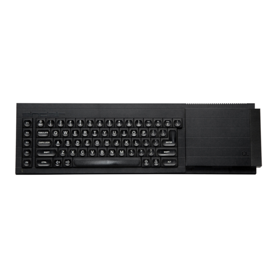
3.6 Keyboard Test 3.6.1 Check that the following is displayed: 3.6.2 Press the key indicated by a dark blue background on the display. The blue background should be replaced by green and move onto the next key. Press all keys in sequence and note that on pressing the ALT key the message: 'keyboard test complete' is displayed momentarily. NOTE: Each key should be pressed individually, NOT skimmed over. -
Page 16: Microdrive 1 Test
3.9.1 Check that the following message is displayed and that MDV2 starts to run and the corresponding red LED is illuminated. 3.9.2 Insert a blank cartridge in MDV1. 3.9.3 After a short delay the following message should be displayed: NOTE: On pressing the space bar two bleeps should be heard and the following message displayed in green: Microdrive 2 test OK 3.10 Microdrive 1 Test 3.10.1 As microdrive 2 test (para 3.9). -
Page 17: End Of Test
3.12 End of Test 3.12.1 On satisfactory completion of Microdrive 1 Test the following message should be displayed on green: QL TEST COMPLETE 3.12.2 Press the RESET pushbutton and check that the display is as shown in para 3.1.1. -
Page 18: Fault Diagnosis And Repair
Rise time: 0.02 µs/cm Multimeter General purpose Colour Television Open market New microdrive cartridges as required, Sinclair Head cleaner Open market Double-sided adhesive tape Open market Extension ribbon/connectors for J11, J12 and front panel LED wiring (to enable operation with cover off) -
Page 19: Fault Diagnosis
2.1.2 With a densely populated board such as in the Sinclair QL, a careful physical examination of the board can sometimes indicate an obvious fault. Burst-out discrete components or an overheated track show up immediately, as do the attentions of an enthusiastic amateur. Bearing in mind the latter, short circuits caused by hairline solder 'splatter' can be of several ohms resistance and can cause some very misleading fault symptoms. - Page 20 © 1983 Sinclair Research Ltd 2.2.2 This indicates that most of the system is working. If the QL does not power up, and display the expected copyright screen, switch off and repeat the power-up operation two or three times. It is possible for the QL to lock-up on start-up and appear lifeless.
- Page 21 2.2.16 Where uncertainty exists as to the best place to start fault finding, carry out the following checks by comparing with a known good board: Pin 32 - VSYNCH Pin 28 - RESETOUTL IC23 Pin 10 - PCENL Pins 30, 31 - XTAL Pin 8 - DCSML Pin 25 - CLOCK Pin 21 - DTACK...
- Page 22 300 DEFine PROCedure stop_all 310 sedes 8,0 320 END DEFine Key-in to turn on drive number n and to keep it spinning continuously. Key-in to stop all drives spinning. start_mdv( stop_all 1. Start microdrive 1. 2. Using an oscilloscope, check that a signal is present from the read head (INA, IC29) and trace it through to the RAW inputs on the 8302. 3.
- Page 23 2.6 Fault-Finding Guide 2.6.1 The following table is not intended to be an exhaustive list of the faults that might occur on the Sinclair QL. It is intended as a guide only to possible courses of action to follow when faults show up in particular areas of the circuit. These areas are listed in the table with sub-headings, in no particular order of priority.
-
Page 24: Firmware Upgrade
Keyboard locks-up after prolonged use. Renew IC24 Renew IC18 Check J5, J6 Renew IC25, IC26 RS232-C/Printer Fails RS232 loopback test. Renew IC23 Renew IC24 Check J9, J10 Network Fails network test. Check TR2 and associated components. Fails sound test: Check TR1 Sound No sound Check R104 (post-Issue 6) -
Page 25: Head Chassis
10. Return EPROMs to Sinclair Research Ltd. FIGURE 4.2 KEYBOARD FORMAT FIGURE 4.3 HEAD CHASSIS... -
Page 26: Monitor Connections
2. KNOWN BUGS 2.1 There are a number of bugs still alive in the QL. Some are rather obscure, but here is a list of the ones that could cause a customer to return a QL as "faulty", together with the clue you should look for when you suspect a bug is the real problem. -
Page 27: Printing Problems
3. PRINTING PROBLEMS 3.1 If a customer complains that his printer will not print more than about a page of output from his QL, he should check the wiring in the lead. 3.2 Many printers require the DTR line to be connected to pin 20. Some of these, by chance, work with the DTR line connected to pin 4, until one... -
Page 28: Ser Outputs
5. HOW TO CURE A CRASHING QL 5.1 You may have a QL that "freezes" after a few hours of operation. We do not yet fully understand why this happens with some computers. 5.2 To cure the problem, take out all the ICs that plug into sockets, in the main pcb. Using some proprietary cleaning fluid, clean the legs of the ICs, and the sockets;... -
Page 29: Appendix B To Section 4 User Hints
The following points may be of help in spotting 'non-faults' on QLs. 1. Please note that if you want the QL to tell you which version of ROM it has, you should enter 'PRINT VER$' and not 'PRINT VERS'. 2. If you try to run Abacus, Archive, Easel or Quill on microdrive 2 instead of microdrive 1, you get an error message, typically 'AT END 200 NOT FOUND'. -
Page 30: Appendix C To Section 4 Mandatory Modifications
3. COLLAR FOR QL MICRODRIVE 2 3.1 On any QL for repair, fit a special collar beneath the far right fixing screw of MDV2 (the screw by the side spring). This is to prevent the lid of the QL from hitting the top of the MDV2 board, which can upset the position of the head. Use a countersunk screw in place of the original one. Collars are available from Sinclair's normal spares distribution channels. - Page 31 FIGURE C3 ISSUE 6 BOARD - SOLDER SIDE (SRL/EI/1119-1)
-
Page 32: Appendix D To Section 4 Microdrive Fault Finding
Faults on Early Microdrives 1. INTRODUCTION 1.1 This guide is intended to give a base of understanding for the most frequent faults occurring on QL microdrives. It contains descriptions of faults and tests to help in finding them. 1.2 The microdrive is a slave mechanism for transferring data to and from magnetic tape. Its role therefore is not interpreting data, but ensuring that data presented to it for writing is read and returned in the same manner. -
Page 33: Faults On Early Microdrives
3.3.1 After writing to tape, carry out the following while in read mode. 1. Check data lines ULA pins 19 (24) and compare to D3. If the waveform is very unstable in X axis, a mechanical fault is probable. If the waveform is poor or is not present at all check the pk-pk signal at pins 4 and 5 (14 and 15). -
Page 34: Microdrive Signals (100 Khz Read)
340 PAUSE 50 350 SAVE ser1 360 END DEFine TABLE D1 - SIGNAL TEST PROGRAM FIGURE D1 FIGURE D2 MICRODRIVE SIGNAL (100 KHZ WRITE) FIGURE D5 FIGURE D3 FIGURE D4 MICRODRIVE SIGNALS (100 KHZ READ) FIGURE D7 FIGURE D8 FIGURE D6 MICRODRIVE SIGNALS (FORMAT READ) - Page 35 FIGURE D9 ULA 2G007 - INTERNAL CIRCUIT...
- Page 36 SECTION 5...
-
Page 37: Parts Lists
1. SERIAL NUMBERS 1.1 The serial number is visible on a label attached to the underside of the Sinclair QL thus: D13 59643. Prefix D13 relates to the build standard (B/S) and Issue Number, 59643, is the number of the production run. -
Page 38: Notes To Tables
2. PARTS LISTS / MODIFICATION HISTORY 2.1 Parts lists for the Sinclair QL are presented in tabular form. They cover p.c. board Issue 5 (build standard D6 to D13) and p.c. board Issue 6 (build standard 14 and beyond). The Issue 6 p.c. board introduces a number of relatively minor circuit changes from Issue 5. These are illustrated in Figures and itemised in Tables 5.1 to 5.5 under separate columns labelled Issue 5 and Issue 6. - Page 39 Keyboard and Bubble Mat Keyboard Assembly Fixings Adhesive Cable Clip Double-sided Tape (0.5-in wide) 1/4-in self-tap - keyboard backplate ROM Cartridge Bung MDV Extension Bung BUS Extension Bung General Assembly Fixings 5/16-in self-tap (4 off) Keyboard/Base 1 1/4-in self-tap (4 off) TABLE 5.2 HEATSINK ASSEMBLY Description Manufacturer/Type...
- Page 40 As Issue 5 5%, 1/4W 5%, 1/4W 5%, 1/4W R100 R101 2K2 5%, 1/4W DIODES 1N4148 1N4148 As Issue 5 1N4148 INTEGRATED CIRCUITS IC29 IC30 2G007-Issue 3 Ferranti As Issue 5 IC31 IC32 78M05 +5V Regulator MISCELLANEOUS HBC1 HBC2 A10021 As Issue 5 2-off each 7-way flex.
- Page 41 5%, 1/4W 5%, 1/4W 680R 5%, 1/4W 5%, 1/4W 5%, 1/4W 5%, 1/4W 5%, 1/4W 330R 5%, 1/4W 330R 5%, 1/4W R17-24 5%, 1/4W 180R 5%, 1/4W 5%, 1/4W 5%, 1/4W 5%, 1/4W 5%, 1/4W 820R 5%, 1/4W 820R 5%, 1/4W 5%, 1/4W 5%, 1/4W 5%, 1/4W...
- Page 42 Texas HYB4164P2BD IC17 74LS00 As Issue 5 IC18 MC68008 Motorola IC19, IC20 74LS257 NOT Nat. Semi IC21 74LS245 NOT Nat. Semi IC22 ZX8301 Plessey/Sinclair IC23 ZX8302 NCR/Sinclair IC24 8049 IC25 1488 IC26 1489A IC27 74LS03 IC28 MC1377P MC1377P Motorola IC33...
-
Page 43: Printed Circuit Board (Issue 5) Component Layout
TE9FS/18B 9-way flex TE11FS/18B 11-way flex HBC1/2 4 off Aries, 7-way flex. socket MWP2P-1B Burndy LEDS (D20, D21, D27) MWP6P-1B Burndy MISCELLANEOUS COMPONENTS 540pF Trimmer UM1233 Astex, E36 Modulator HC18-U 15MHz, 20ppm MX38 As Issue 5 32.768kHz, 20ppm HC18T-U 4.4336MHz, 20ppm 11MHz, 10ppm RESET P/B Switch... -
Page 44: History Sheet
Table of Contents Sinclair QL Service Manual List of Contents List of Illustrations History Sheet SECTION 1 SYSTEM DESCRIPTION LIST OF CONTENTS 1. INTRODUCTION 2. ARCHITECTURE 3. MC68008 CPU 4. INTEL 8049 INTELLIGENT PERIPHERAL CONTROLLER (IPC) 5. MEMORY ORGANISATION 5.1 Introduction 5.2 Read/Write Operations... - Page 45 4. SER OUTPUTS 5. HOW TO CURE A CRASHING QL 6. FLICKERING DISPLAYS APPENDIX B TO SECTION 4 USER HINTS APPENDIX C TO SECTION 4 MANDATORY MODIFICATIONS 1. FITMENT CHECKS 2. IMPROVEMENT TO MICRODRIVE PERFORMANCE 3. COLLAR FOR QL MICRODRIVE 2 APPENDIX D TO SECTION 4 MICRODRIVE FAULT FINDING 1.
Need help?
Do you have a question about the QL and is the answer not in the manual?
Questions and answers