Table of Contents
Advertisement
DOLBY
Manufactured under license from Dolby Laboratories.
"Dolby" and the double-D symbol are trademarks of
Dolby Laboratories. Confidential Unpublished Works.
©1992-1997 Dolby Laboratories, Inc. All rights reserved.
This product incorporates copyright protection technology that is protected by
U.S. patents and other intellectual property rights. Use of this copyright protection
technology must be authorized by Macrovision, and is intended for home and other
limited pay-per-view uses only unless otherwise authorized by Macrovision.
Reverse engineering or disassembly is prohibited.
Pace and
are trademarks and/or registered trademarks of
Pace Micro Technology plc.
HDMI, the HDMI logo and High-Definition Multimedia Interface are trademarks or
registered trademarks of HDMI Licensing LLC.
Other trademarks listed herein are the property of their respective owners.
The model and serial number of the Pace TDC775D are on a label on
its base.
Copyright © 2005 Pace Micro Technology plc All rights reserved
Advertisement
Table of Contents

Related Manuals for Pace TDC775D


Summary of Contents for Pace TDC775D
- Page 1 HDMI Licensing LLC. Other trademarks listed herein are the property of their respective owners. The model and serial number of the Pace TDC775D are on a label on its base. Copyright © 2005 Pace Micro Technology plc All rights reserved...
-
Page 2: Table Of Contents
CONNECTING THE EQUIPMENT ....15 TDC775D DVR FUNCTIONS ..... . . 42 Activating baseband loopthrough for a DVD MAKING HDTV-DISPLAY SETTINGS . -
Page 3: Safety Information
Service address: The exclamation point within a triangle is Pace Micro Technology (Support Services) Ltd. intended to alert you to the presence of 3701 FAU Boulevard, Suite 200... -
Page 4: Important Safety Instructions
IMPORTANT SAFETY INSTRUCTIONS Before you install or use the apparatus, you must read 10. Protect the power cord from being walked on or pinched and understand these Important Safety Instructions. particularly at plugs, convenience receptacles, and the point At all times when using the apparatus you must follow where they exit from the apparatus. - Page 5 SAFETY INFORMATION (cont.) In addition to the Important Safety Instructions, please read the Ventilation Safety Information below. Slots and openings in the casing of the set-top are provided for ventilation, to ensure reliable operation of the set-top and to Power sources protect it from overheating.
- Page 6 SAFETY INFORMATION (cont.) Risk of fire or scorching Power lines Never place naked flame sources, such as lighted candles, on the You must not locate an outside antenna system in the vicinity of set-top. overhead power lines or other electric light or power circuits, or where it can fall into such power lines or circuits.
- Page 7 SAFETY INFORMATION (cont.) Safety check Safety aspects of connections Upon completion of any servicing or repairs to the set-top, ask the Full details of the rear panel are on page 10. service technician to perform safety checks to determine that the Connecting set-top is in its proper operating condition.
- Page 8 SAFETY INFORMATION (cont.) Epilepsy and on-screen images Regulatory information Certain people are susceptible to epileptic seizures or losing CAUTION: Do not attempt to modify the set-top without consciousness when faced with certain types of flashing lights in our written authorization from the manufacturer. Unauthorized daily environment.
-
Page 9: Overview
OVERVIEW • Read all the safety information on page 2 through 7. Using the TV’s HDMI connector: • Familiarize yourself with the front and rear panels of the set-top (see page 9 and page 10). HDMI TV (+ optional home theater Set-up A receiver) •... -
Page 10: Front Panel
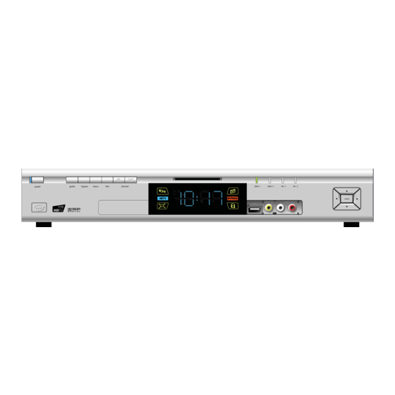
FRONT PANEL channel U U U U and D D D D play/record lights L, R, U and D menu front-panel display To display on-screen menus To change channel up or Indicate the play and record Appears when the set-top is To move left/right/up/ bypass down... -
Page 11: Rear Panel
REAR PANEL COMPONENT AUDIO IN SECONDARY 1394 DIGITAL AUDIO OUT VIDEO OUT Audio baseband input AUDIO OUT For connection Electrical S/PDIF audio output Component video output (stereo, L and R) Audio baseband outputs to a 1394- for analog HDTV (stereo, L and R) compatible S-VIDEO device... - Page 12 REAR PANEL (cont.) CABLE IN Connect the cable service here. Connect to compatible optional equipment that (UNIVERSAL supports a USB 1.1 interface, for example: a TO TV Connect to the RF/antenna input on a TV or VCR. SERIAL BUS) printer, digital camera, keyboard or mouse. COMPONENT If the HDTV does not have an HDMI (see ETHERNET...
-
Page 13: Getting The Cables Ready
GETTING THE CABLES READY Below is a list of cables (and their connectors) that are shown in the diagrams on page 13 through 34, along with a key to how they are depicted in the diagrams. (Options are shown as dashed lines.) Cable type Connector type Cable numbers... -
Page 14: Connecting A Vcr Controller (Ir Transmitter)
VCR controller will cause the VCR to record at those times. The Pace VCR controller for use with this set-top is not supplied with the set-top. Contact the cable operator for details. It has an emitter that is designed to stick near to the remote-control sensor of the VCR it controls. -
Page 15: Connecting A Remote Eye (Ir Receiver)
CONNECTING A REMOTE EYE (IR receiver) You may need to install the set-top in an equipment closet with closed non-transparent doors or front of some other location where the remote-control sensor (IR-receive window) on the set-top’s front HDTV panel is blocked from view (for example, if the TV is wall-mounted). In that case, you need to connect a remote eye (IR receiver) to the set-top’s rear panel. -
Page 16: Connecting The Equipment
CONNECTING THE EQUIPMENT On the following pages are diagrams that show you how to connect typical Using the TV’s HDMI connector: equipment (HDTV, VCR, DVD player and home theater receiver) to the set-top. The connected items are shown individually and then in combination (see the HDMI TV (+ optional home theater Set-up A tables, right). -
Page 17: Set-Up A: Hdmi Tv (+ Optional Home Theater)
CONNECTING THE EQUIPMENT (cont.) Set-up A: HDMI TV (+ optional home theater) HDTV COMPONENT VIDEO IN Y IN RF CABLE S-VIDEO PB/CB IN HDMI VIDEO IN PR/CR IN ANTENNA/ POWER RF IN LEFT LEFT AUDIO IN AUDIO IN RIGHT RIGHT HOME THEATER AUDIO IN AUDIO IN... - Page 18 • When you add a home theater receiver, the set-top’s audio connection to the TV (via HDMI) is not needed, so you may wish to mute (turn off) the audio on the TV Cable Wiring Diagram A TDC775D Cable TV HDTV...
-
Page 19: Set-Up B: Dvi Tv (+ Optional Home Theater)
CONNECTING THE EQUIPMENT (cont.) Set-up B: DVI TV (+ optional home theater) HDTV COMPONENT VIDEO IN Y IN S-VIDEO PB/CB IN VIDEO IN PR/CR IN ANTENNA/ POWER RF CABLE RF IN LEFT LEFT AUDIO IN AUDIO IN RIGHT RIGHT AUDIO IN AUDIO IN HOME THEATER RECEIVER... - Page 20 • To enhance the sound, you can connect a home theater receiver, using the set-top’s DIGITAL AUDIO OUT connector (as shown) or its OPTICAL AUDIO OUT connector. In that case, cable 3 is not needed. Cable Wiring Diagram B Cable TV TDC775D HDTV RF Cable TV DVI & Audio set-top...
-
Page 21: Set-Up C: Vcr And Hdmi Tv
CONNECTING THE EQUIPMENT (cont.) Set-up C: VCR and HDMI TV RF CABLE HDTV S-VIDEO VIDEO OUT VIDEO IN TV / RF LEFT LEFT COMPONENT POWER AUDIO OUT AUDIO IN VIDEO IN S-VIDEO ANTENNA/ RIGHT RIGHT RF IN Y IN AUDIO OUT AUDIO IN S-VIDEO PB/CB IN... - Page 22 CONNECTING THE EQUIPMENT (cont.) About Set-up C: Using an HDMI cable to connect a TV and S-video cable to connect a VCR In this set-up, a VCR is added to the basic set-up. The way in which you connect the HDTV to the set-top (either HDMI or component video) does not affect the way you connect the VCR.
- Page 23 CONNECTING THE EQUIPMENT (cont.) Cable Wiring Diagram C TDC775D Cable TV HDTV HDMI or [DVI & Audio] RF Cable TV set-top Audio & Video Recorder Cable Wiring Diagram D Cable TV HDMI or [DVI & Audio] TDC775D RF Cable TV...
-
Page 24: Set-Up D: Vcr, Home Theater And Hdmi Tv
CONNECTING THE EQUIPMENT (cont.) Set-up D: VCR, Home Theater and HDMI TV RF CABLE HDTV S-VIDEO VIDEO OUT VIDEO IN TV / RF LEFT LEFT POWER COMPONENT AUDIO OUT AUDIO IN VIDEO IN S-VIDEO ANTENNA/ RIGHT RIGHT RF IN Y IN AUDIO OUT AUDIO IN S-VIDEO... - Page 25 CONNECTING THE EQUIPMENT (cont.) About Set-up D: Adding a home theater receiver to Set-up C All of the points mentioned in Set-up C apply • To enhance the sound, connect a home theater receiver. • There is a choice of two S/PDIF outputs: (i) electrical (labeled DIGITAL AUDIO OUT, which is shown connected by cable 8 in the diagram, opposite) and (ii) optical (labeled OPTICAL AUDIO OUT).
-
Page 26: Set-Up E: Dvd And Hdmi Tv
CONNECTING THE EQUIPMENT (cont.) Set-up E: DVD and HDMI TV HDTV COMPONENT VIDEO IN Y IN COMPONENT S-VIDEO VIDEO OUT PB/CB IN HDMI DIGITAL AUDIO OUT VIDEO IN LEFT PR/CR IN ANTENNA/ POWER POWER AUDIO OUT PB/CB RF IN COAXIAL OPTICAL LEFT LEFT... - Page 27 The set-top must be turned off for this audio loopthrough to occur. Cable Wiring Diagram E Cable TV HDMI or [DVI & Audio] TDC775D HDTV RF Cable TV set-top Audio & Video...
-
Page 28: Set-Up F: Vcr, Dvd, Home Theater And Hdmi Tv
CONNECTING THE EQUIPMENT (cont.) RF CABLE Set-up F: VCR, DVD, Home Theater VIDEO IN S-VIDEO VIDEO OUT TV / RF and HDMI TV LEFT LEFT POWER HDTV AUDIO IN AUDIO OUT ANTENNA/ S-VIDEO RIGHT RIGHT RF IN AUDIO IN AUDIO OUT RF CABLE COMPONENT VIDEO IN... - Page 29 • The digital audio output from the DVD player loops through the set-top to the home theater receiver. For this to occur, the set-top must be turned off. Cable Wiring Diagram F Cable TV RF Cable TV HDMI or [DVI & Audio] TDC775D HDTV set-top Digital Audio Home Theater...
-
Page 30: Set-Up G: Component-Video Hdtv (+ Optional Home Theater)
CONNECTING THE EQUIPMENT (cont.) Set-up G: Component-video HDTV (+ optional home theater) HDTV COMPONENT VIDEO IN Y IN S-VIDEO PB/CB IN VIDEO IN PR/CR IN ANTENNA/ POWER RF CABLE RF IN LEFT LEFT AUDIO IN AUDIO IN RIGHT RIGHT AUDIO IN AUDIO IN HOME THEATER RECEIVER... - Page 31 • There is a choice of two S/PDIF outputs: (i) electrical (labeled DIGITAL AUDIO OUT, which is shown connected, by cable 8 in the diagram, opposite) and (ii) optical (labeled OPTICAL AUDIO OUT). Cable Wiring Diagram G TDC775D Cable TV HDTV RF Cable TV Y, Pb, Pr &...
-
Page 32: Set-Up H: Dvd And Component-Video Hdtv (+ Optional Home Theater)
CONNECTING THE EQUIPMENT (cont.) Set-up H: DVD and Component-video HDTV (+ optional home theater) HDTV RF CABLE COMPONENT VIDEO IN Y IN COMPONENT VIDEO OUT S-VIDEO PB/CB IN DIGITAL AUDIO OUT VIDEO IN LEFT PR/CR IN POWER PB/CB AUDIO OUT ANTENNA/ POWER RF IN... - Page 33 CONNECTING THE EQUIPMENT (cont.) About Set-up H: Using component-video cables to connect a DVD player and an HDTV In this set-up, a DVD player is added to Set-up G. • As the HDTV has component video inputs, you can loop the DVD player’s video through the set-top, using cables 9 and 12, as shown.
- Page 34 CONNECTING THE EQUIPMENT (cont.) Cable Wiring Diagram H Cable TV RF Cable TV Y, Pb, Pr Video TDC775D HDTV set-top Home Y, Pb, Pr Video & Digital Audio Theater Player...
-
Page 35: Set-Up I: Vcr, Dvd, Home Theater And Component-Video Hdtv
CONNECTING THE EQUIPMENT (cont.) Set-up I: VCR, DVD, RF CABLE Home Theater and Component-video HDTV VIDEO IN S-VIDEO VIDEO OUT TV / RF LEFT LEFT POWER HDTV AUDIO IN AUDIO OUT ANTENNA/ S-VIDEO RIGHT RIGHT RF IN AUDIO IN AUDIO OUT RF CABLE COMPONENT VIDEO IN... - Page 36 COMPONENT VIDEO IN jacks is only to the COMPONENT VIDEO OUT jacks. It is not looped though to the VIDEO OUT jack or S-VIDEO OUT jack. Cable Wiring Diagram I Cable TV RF Cable TV Y, Pb, Pr Video TDC775D HDTV set-top Digital Audio Home Theater...
-
Page 37: Connecting To The Ac Power Supply
CONNECTING TO THE AC POWER SUPPLY S-VIDEO VIDEO IN VIDEO OUT TV / RF LEFT LEFT POWER HDTV AUDIO IN AUDIO OUT ANTENNA/ S-VIDEO RIGHT RIGHT RF IN AUDIO IN AUDIO OUT COMPONENT VIDEO IN Y IN COMPONENT S-VIDEO VIDEO OUT PB/CB IN HDMI DIGITAL AUDIO OUT... -
Page 38: Connecting The Tv To The Ac Power Supply
CONNECTING TO THE AC POWER SUPPLY (cont.) WARNINGS Do not connect the set-top (or any other equipment such as a TV or VCR) to the AC power supply until you have properly connected all the other cables. Do not defeat the safety purpose of the polarized plugs on power cords. A polarized plug has two blades with one wider than the other. -
Page 39: Turning On And Tuning In
TURNING ON AND TUNING IN Turning the set-top on and off After you have connected the set-top to the AC wall outlet (and switched this outlet ON, if it has a switch), wait until you can see the time on its front-panel display. Press the button labeled power on the front panel of the set-top to turn it on. - Page 40 TURNING ON AND TUNING IN (cont.) You should now be able to see on the TV a program that is coming from the set-top. If you cannot Find out from the cable operator whether the set-top’s RF output is channel 3 or see a program, check that the RF coaxial cables are securely and correctly connected (see the set-up diagrams).
-
Page 41: Rf Bypass
RF BYPASS You use the RF bypass feature to make the regular (analog) channels bypass the set-top and pass directly to the TV and/or VCR. For the RF bypass to work, the equipment must be connected by RF leads (see the diagram, right). Other connections are possible in addition to those shown (see connections A to I) provided that the RF connection is included. - Page 42 RF BYPASS (cont.) Turning bypass on and off To turn on the bypass feature, press the bypass button on the set-top’s front panel. To turn it off, press bypass again. While the bypass is on, the word BYPASS is lighted on the set-top’s front panel. About the bypass feature If the TV has an RF input only, you can watch only regular (analog) channels while the bypass feature is turned on.
-
Page 43: Tdc775D Dvr Functions
The TDC775D set-top has an internal hard disk that is used to record and play back television NOTE programs, giving much more control of the viewing experience. For example, you can pause live The exact functionality of the DVR television and resume viewing from the point at which you left off. You can also use the set-top to depends on the on-screen program record favorite programs, and watch one program while recording another. -
Page 44: Making Hdtv-Display Settings
Putting the set-top into “HDTV settings mode” 1. Make sure that the set-top is switched on. 2. Press the power button on the set-top, then within 1 second, press the Pace Power Menu menu button. TV Aspect Capability TV Display Capability The front panel displays “ASPt”... - Page 45 MAKING HDTV-DISPLAY SETTINGS (cont.) If a screen is connected and set up, the HD Power Menu is displayed. As you use this menu, the front- panel display changes, as shown right. Therefore, if you do not have a TV or monitor set up, you can use the front panel display to help you change the settings.
- Page 46 MAKING HDTV-DISPLAY SETTINGS (cont.) Explanation of screen aspect ratio Use the HDTV-display menu (see page 44) to set the correct aspect ratio (width-to-height ratio) for the TV. If it is a wide-screen TV, set 16:9 (otherwise set 4:3). Standard definition 4:3 transmission Appropriate TV Display (see page 48) and Aspect-Ratio settings should ensure that the picture, on the HDTV screen, is not distorted (stretched or squashed) and that it fills as much of the screen as...
- Page 47 MAKING HDTV-DISPLAY SETTINGS (cont.) EXAMPLE 1: you have a 4:3 HDTV, connected by HDMI or COMPONENT VIDEO jacks, and the menu settings are 1080i (or 720p) and 4:3 Reduced picture sizes you may see, depending on the different ways the picture can be transmitted EXAMPLE 2: you have a 16:9 HDTV, connected by HDMI or COMPONENT VIDEO jacks, and the menu settings are 1080i (or 720p) and 16:9 Picture sizes you may see, depending on the different ways...
- Page 48 MAKING HDTV-DISPLAY SETTINGS (cont.) Setting the TV Aspect Ratio If you have not done so, put the set-top into “HDTV settings mode”, as described on page 43. The front panel displays “ASPt”, shown right. The flow diagram on the far right shows how you use the arrow and select buttons on the set- top’s front panel to change the display and make the settings.
- Page 49 MAKING HDTV-DISPLAY SETTINGS (cont.) About TV Display (resolution settings) NOTE You must make the appropriate TV Display setting(s) on the set-top, so that it is compatible with the When an HDTV/monitor with a HDMI is connected to the set-top, In order to display the best picture every time, you should select every resolution that the TV is the set-top requests information about its display.
- Page 50 MAKING HDTV-DISPLAY SETTINGS (cont.) Changing the TV Display Capability If you have not done so already, put the set-top into “HDTV settings mode”, as described on page 43. The front panel displays “ASPt”. The flow diagram on the right shows how you use the arrow and select buttons on the set-top’s front panel to change the display and make the settings.
- Page 51 MAKING HDTV-DISPLAY SETTINGS (cont.) Auto Pillarbox If the TV connected to the set-top is a 16:9 TV that does not automatically detect 4:3 transmissions (and therefore does not add black bars to the sides of the picture), then 4:3 transmissions may display “stretched”...
- Page 52 MAKING HDTV-DISPLAY SETTINGS (cont.) 2. Press the button. Either “On” (switched on) or “Off ” (switched off) displays. If you can see the Auto Pillarbox? on-screen menus, the menu shown right displays. 3. If you want to change the setting, press .
- Page 53 MAKING HDTV-DISPLAY SETTINGS (cont.) Making Closed Caption settings Closed captioning is a means of displaying alerts and subtitles on the TV screen, superimposed on whatever the viewer is watching. You can turn closed captions on or off, as required, and you can also change the closed captions’...
- Page 54 MAKING HDTV-DISPLAY SETTINGS (cont.) Making Closed Caption settings Closed captioning is a means of displaying alerts (for example, hurricane warnings) and subtitles on Size Small Font Style 1 the TV screen, superimposed on whatever is being watched. Character Color Character Shading Auto Use the HDTV-display menu (see page 44) to turn closed captions on, if required (the default is off).
- Page 55 MAKING HDTV-DISPLAY SETTINGS (cont.) Front Panel Settings Occasionally, the brightness of the set-top's front panel LED display may change, for example the LED display may dim automatically when the set-top is put in standby. You can use the Front Panel Settings to set the brightness levels of the display at its brightest and dimmest.
- Page 56 MAKING HDTV-DISPLAY SETTINGS (cont.) Restoring the factory default settings If you wish, you can restore the HDTV factory settings. All the changes you have made will be lost and the settings will revert to those which were programmed in the factory. The factory settings are: HDTV menu item Options Factory default setting...
- Page 57 MAKING HDTV-DISPLAY SETTINGS (cont.) If you have not done so, put the set-top into “HDTV settings mode”, as described on page 43. The front panel displays “ASPt”. The flow diagram on the right shows how you use the arrow, select and power buttons on the set-top’s front panel to change the display and make the settings.
-
Page 58: Using The Setup Menus
USING THE SETUP MENUS The Setup menus allow you to make further settings to control how your set-top works. These are available from the TV Guide and should be fully described in the information provided by the cable service provider. Also there may be on-screen information to explain these menus. -
Page 59: Solving Problems
SOLVING PROBLEMS If the installed system does not seem to be working properly, first make sure that all the cables are securely connected, then carry out the following checks, in the order shown. Check Suggested solution Further checks, if there is still a problem Is anything lighted on Power may not be reaching the set-top. - Page 60 SOLVING PROBLEMS (cont.) Check Suggested solution Further checks, if there is still a problem Can you see a picture The TV and other equipment may not be Make sure the RF-bypass feature is turned OFF (the on the TV screen? turned on.
- Page 61 SOLVING PROBLEMS (cont.) Check Suggested solution Further checks, if there is still a problem Is there any sound? Check that the audio cables are securely Check that you have not muted the sound on the and correctly connected. set-top and/or TV. Adjust the volume on the set- top and/or TV.
-
Page 62: Apparent "Problems" That May Be Caused By Certain Menu Settings
SOLVING PROBLEMS (cont.) Apparent “problems” that may be caused by certain menu settings Problem Reason No audio There is a menu to select a second soundtrack (SAP: secondary audio program). If this is selected, but no SAP is being transmitted, there may be no audio. The HDTV turns off when you If the HDTV is attached to the AC outlet on the set-top’s rear panel, it will be affected by a menu play the DVD player or other...
Need help?
Do you have a question about the TDC775D and is the answer not in the manual?
Questions and answers