Table of Contents
Advertisement
Advertisement
Table of Contents

Subscribe to Our Youtube Channel
Related Manuals for TeeJet Boompilot Matrix Pro 840G


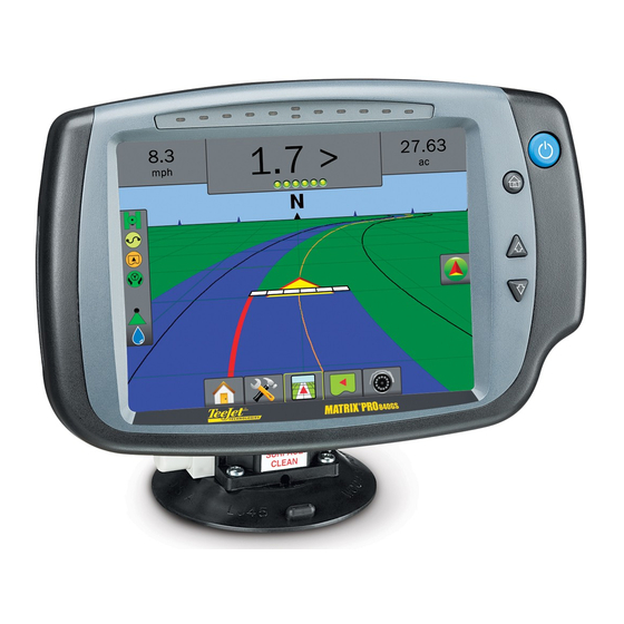
Summary of Contents for TeeJet Boompilot Matrix Pro 840G
- Page 1 B o o m P i l o t ® S e t u P G u i d e Automatic Boom Section Control...
-
Page 3: Table Of Contents
Setup Instructions for BoomPilot ® Table of Contents BoomPilot® with matrix® Pro General information for your matrix® Pro Setup Option Information ......................1 Drop Down Menu Selections ...................... 1 Keyboard Entry Screen ......................2 GPS iS required GPS Type ...........................4 GPS Port ...........................4 External Receiver Minimum Configuration Requirements ............ - Page 4 Overlap ..........................14 Delay On ..........................14 Delay Off .........................15 BoomPilot - Single Boom Setup ..................16 Guidance Width ......................17 Spray Width ........................17 www.teejet.com...
-
Page 5: Boompilot® With Matrix® Pro
BoomPilot® with matrix® Pro Copyrights © 2011 TeeJet Technologies. All rights reserved. No part of this document or the computer programs described in it may be reproduced, copied, photocopied, translated, or reduced in any form or by any means, electronic or machine readable, recording or otherwise, without prior written consent from TeeJet Technologies. - Page 6 www.teejet.com...
-
Page 7: General Information For Your Matrix® Pro
Setup Instructions for BoomPilot ® General information for your matrix® Pro The Matrix Pro is used to configure the vehicle and its implements including auto steering and tilt. Setup Option Information Press the icon of any menu item to display a definition and range values of that item. To remove the information box, press anywhere on the screen. -
Page 8: Keyboard Entry Screen
Dist to Boom (ft) Vehicle Type Vehicle Type Front Wheel Front Wheel 0.00 Ant Height 12.50 ft Ant Height 12.50 ft Clear Dir to Boom Backward Dir to Boom Backward <-- Dist to Boom 0.00 ft Dist to Boom 0.00 ft www.teejet.com... -
Page 9: Gps Is Required
►GPS Port – sets (D)GPS COM port ►GPS Status – displays information for TeeJet Customer Service use on GGA/VTG (Data Rates), Number of Satellites, HDOP, PRN, GGA Quality, GPS Receiver and Receiver Version. 4. Press RETURN arrow or CONFIGURATION side tab to return to the main Configuration screen. -
Page 10: Gps Type
5 Hz and transmit out Optional VTG 5 Hz, 2 Hz, Off ►External – receive external (D)GPS data 0.2 Hz NOTE: Working with GPS signals such as Omnistar HP/XP or RTK will require GPS port to be set to External. www.teejet.com... -
Page 11: Gps Status
Setup Instructions for BoomPilot ® GPS Status GPS Status displays information regarding data rates, number of satellites in view, and satellite quality and ID. 1. Press Information 2. View data including: ◄GGA/VTG (Data Rates) – the number of GPS positions per second. ◄Num Sats –... -
Page 12: Gga Requirements
GGA Quality required to be able to work with various types of signal can vary. See table below for requirements. Service Indicator Accuracy GPS only <3 m WAAS/EGNOS/Beacon <1 m 4 cm Omnistar HP/XP 10 cm Glide <1 m Receivers Receiver Indicator Version Uninitialized Unknown Other Novatel CSI (Hemisphere SXII) 6.8k or 6.8pa OEMstar 01011 OEMstar Glo 01011 www.teejet.com... -
Page 13: Boompilot Configuration Using Your Matrix® Pro
Setup Instructions for BoomPilot ® BoomPilot ConfiGuration uSinG your matrix® Pro The Matrix Pro is used to configure the vehicle and its implements. To access BoomPilot configuration options: 1. Press UNIT SETUP bottom tab 2. Press CONFIGURATION side tab 3. Select from: ►Vehicle –... -
Page 14: Vehicle Setup
NOTE: All settings under Vehicle Setup are required for autosteer and tilt sensor operation, as well as proper BoomPilot operation. Figure 1-10: Vehicle Setup Options Configuration Implement Vehicle Config-> Vehicle AutoSteer Tilt Vehicle Type Front Wheel Lightbar Ant Height 12.50 ft Video Dir to Boom Backward Dist to Boom 0.00 ft www.teejet.com... -
Page 15: Vehicle Type
Setup Instructions for BoomPilot ® Vehicle Type Antenna Height Vehicle Type selects the type of vehicle steering that Antenna Height sets the height of the antenna from the most closely represents your vehicle. Default is Front ground. Range is 0.0 - 32.8 feet / 0.0 - 10.0 meters. Wheel. -
Page 16: Direction To Boom
Ant Height 12.50 ft Dir to Boom Backward Vehicle Type Front Wheel Ant Height 12.50 ft Dist to Boom 0.00 ft Dist to Boom (ft) Dir to Boom Backward Backward Dist to Boom 0.00 ft Forward 0.00 Clear <-- www.teejet.com... -
Page 17: Boompilot - Smartcable Or Sdm
Setup Instructions for BoomPilot ® BoomPilot - SmartCable or Sdm Figure 1-15: Implement Setup Options with SmartCable or SDM BoomPilot setup is used to establish number of boom sections, guidance width, spray width, overlap Configuration percentage, implement delay on time and implement delay off time. -
Page 18: Number Of Boom Sections
2. Select the number of boom sections on the Figure 1-17: Guidance Width implement: Figure 1-16: Number of Boom Sections Config->Implement Config->Implement Num Sections Num Sections Guidance Width 60.00 ft Guidance Width 75.00 ft Spray Width 180.00 ft Spray Width 75.00 ft Guidance Width (ft) Clear <-- www.teejet.com... -
Page 19: Spray Width
Setup Instructions for BoomPilot ® Figure 1-18: Spray Width Spray Width Spray Width establishes the width of each implement Config->Implement section. Range is 0.0 - 2952.7 inches / 0.0 - 75.0 meters. Default per section is 144.0 inches / 3.66 meters. -
Page 20: Overlap
2. Use the entry screen to establish the delay on time. Figure 1-19: Overlap Figure 1-20: Delay On Config->Implement (2) Config->Implement (2) Overlap Overlap Delay On 1.00 s Delay On 1.00 s 100% 1.00 s Delay Off Delay Off 1.00 s Delay On Time (s) Clear <-- 100% www.teejet.com... -
Page 21: Delay Off
Setup Instructions for BoomPilot ® Delay Off Delay Off functions as a “look ahead” for establishing the timing for the boom section valves to switch off exactly when entering an area that has been applied. If the boom turns off too soon when entering an applied area, decrease the Delay Off setting. -
Page 22: Boompilot - Single Boom Setup
4. Press RETURN arrow or CONFIGURATION side tab to return to the main Configuration screen. Figure 1-22: Implement Setup Options with No SDM Configuration Implement Vehicle Config->Implement AutoSteer Tilt Num Sections Lightbar Guidance Width 60.00 ft Video Spray Width 12.00 ft www.teejet.com... -
Page 23: Guidance Width
Setup Instructions for BoomPilot ® Guidance Width Spray Width Guidance Width establishes the width between the Spray Width establishes the width of the implement. guidelines. Range is 34.0 - 2952.7 inches / 0.9 - 75.0 Range is 34.0 - 2952.7 inches / 0.9 - 75.0 meters. meters. - Page 24 (ABSC) or BoomPilot options on the vehicle through the Matrix Pro console. Please review this manual thoroughly after completing the installation process. 1801 Business Park Drive Springfield, Illinois 62703 USA Tel: (217) 747-0235 • Fax: (217) 753-8426 www.teejet.com 98-05243 R0 © TeeJet Technologies 2011...
Need help?
Do you have a question about the Boompilot Matrix Pro 840G and is the answer not in the manual?
Questions and answers