Table of Contents
Advertisement
Advertisement
Table of Contents

Related Manuals for Electrolux affinity


Summary of Contents for Electrolux affinity
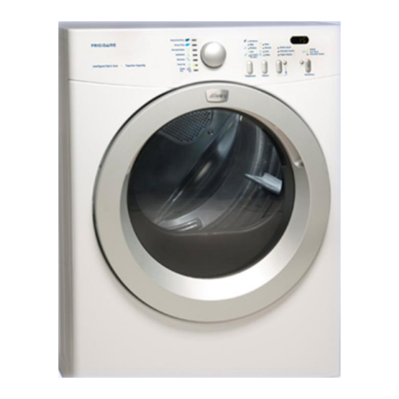
- Page 1 Affinity Dryer Service...
-
Page 2: Exhaust Requirements
Exhaust Requirements... - Page 3 Exhaust Requirements...
- Page 4 Exhaust Requirements • Use only 4 inch (10.2 cm) diameter (minimum) rigid or flexible metal duct and approved vent hood which has a swing-out damper(s) that open when the dryer is in operation. • Do not use plastic flexible duct to exhaust the dryer. •...
- Page 5 Exhaust Requirements...
- Page 6 Exhaust Requirements...
- Page 7 INSTALLATION IN RECESS OR CLOSET 1. A dryer installed in a bedroom, bathroom, recess or closet, MUST be exhausted outdoors. 2. No other fuel burning appliance shall be installed in the same closet as the Gas dryer. 3. Your dryer needs the space around it for proper ventilation. DO NOT INSTALL YOUR DRYER IN A CLOSET WITH A SOLID DOOR.
- Page 8 Exhaust Requirements Right Side or Floor Venting Exhaust Kit, P/N 131456800...
- Page 9 Teardown and Component Operation...
- Page 10 Main Top Remove the two screws on the rear of the main top. Slide back...
- Page 11 Main Top The top panel is held in place in the front by 3 plastic tabs on the console and 2 metal tabs, one on each side.
- Page 12 Console Remove 4 screws two screws on each side holding the console to the top of the side panels...
- Page 13 Console Top tabs Lift the three tabs on the top of the console from the mounting plate and roll the console forward, while lifting up to release the bottom tabs from the front panel. Bottom tabs...
-
Page 14: Control Board
Control Board Disconnect wires and remove 5 screws. -
Page 15: Door Removal
Door Removal Remove the two screws that secure the hinge to the front panel and lift up . -
Page 16: Door Disassembly
Door Disassembly Remove the 7 screws that hold the inner and outer door together. Lift inner door out of outer door. - Page 17 Door Disassembly Hinge & Strike Plate Removal Remove the 4 screws that secure the hinge and the strike plate to the outer door. 2 on each side.
- Page 18 Door Disassembly Door Glass Removal Remove the 2 metal brackets.
-
Page 19: Front Panel
Front Panel Remove the 2 screws, one on each side, on the top of the panel... - Page 20 Front Panel Remove the 2 screws at the bottom of the front panel.
- Page 21 Front Panel Release the spring loaded tabs about half way down the front panel and lift up and out.
-
Page 22: Front Drum Support
Front Drum Support Remove 4 screws and lift the support up and out. - Page 23 Front Drum Support Remove these two screws to gain access to the lint filter housing. Front drum rollers. To replace, remove plastic triangular retainer...
- Page 24 Front Drum Support On the front side of the support, the roller post can be removed by unscrewing this nut.
-
Page 25: Removing The Drum
Removing the Drum Then, push the idler pulley to the left and roll the belt off of the Place your pulley. Then pull the drum out. arms through these openings. -
Page 26: Rear Rollers
Rear Rollers With the drum out, the three rear rollers can be accessed. They are removed the same way as the front rollers. -
Page 27: Heater Assembly
Heater Assembly The heater assembly sits on the left side of the unit. It has two wires connected to it to supply power. As well as the control thermostat and a high limit thermostat. To remove the thermostats, remove the electrical connections and the two screws that hold the thermostat to the... - Page 28 Heater Assembly To remove the heater assembly. Disconnect the electrical connections to the heater and the thermostat. Then remove the two screws that secure the assembly to the post. Then pull the assembly out.
- Page 29 Impellor Remove the two front screws, and unscrew the impellor from the motor shaft. Then pull the whole impellor housing assembly out from the unit. Thermistor...
- Page 30 Motor With the impellor unscrewed from the motor shaft, the motor can now be removed. To remove the motor, unplug the electrical connection, remove the rear clip. Then remove the front clip as shown below. Rear clip Front clip...
-
Page 31: Idler Pulley
Idler Pulley To replace the pulley arm, remove the spring “C” Clip and then pull up. Once the assembly is removed, you can remove the pulley wheel by removing the “C” clip on the arm shaft and then pull the wheel off. Spring... - Page 32 Drum Drum Felt When replacing The drum felt creates the drum, it can the air seal. The felt is be placed in the glued on. If it needs to dryer in any be replaced, all left over direction. glue needs to be removed, before the new felt is installed.
-
Page 33: Reading Error Codes
Reading Error Codes Press and hold SELECT and CANCEL buttons simultaneously for 6 seconds to reset control. The buzzer will sound 1 time and “rES” will show in the display. Immediately after, rotate cycle selector knob 2 turns counterclockwise to the third position from the top and the press and hold the SELECT and CANCEL buttons simultaneously for 6 seconds. -
Page 34: Error Codes
Error Codes Error Code Description Moisture Sensor: Oscillation Frequency to High Door Open at Cycle Start Door Sensing Failure Door Open During Cycle Execution Motor Relay Failure Motor Fault- Motor Stopped or Not Starting Motor Sensing Failure Heater Relay Failure Heater to Earth Ground Failure... - Page 35 Error Codes Error Code Description Heater Open Circuit Heater Thermostat Trip Count too High High Limit Thermostat Circuit Open Heater Sensing Failure Thermal Limiter Open Circuit NTC 1 Open Circuit NTC 1 Short Circuit No Communication Between Main Board and User Interface Protocol incongruence between main board and User Interface...
- Page 36 Error Codes Error Code Description Machine Configuration Error Cycle Configuration Error Incongruence Between Selector and Cycle Tables Power Supply Frequency Out of Limits Power Supply Voltage too High Power Supply voltage too Low Power Supply Polarity Reversed. Main V Sensing Failure...
-
Page 37: Service Diagnostics
Service Diagnostics • Press and hold SELECT and CANCEL buttons simultaneously for 6 seconds to reset control. The buzzer will sound 1 time and “rES” will show in the display. • Immediately after, rotate cycle selector knob 5 turns counter-clockwise to the second position from the bottom. - Page 38 Service Diagnostics • Rotate the cycle selector knob clockwise from the starting position • 0 turns: All LED’s will flash. • 1 turn: Drive motor runs; heat source is on. Drying LED is lit. “H” and the control thermistor reading will toggle back and forth in the display. •...
- Page 39 Service Diagnostic • 4 turns: Drive motor runs; heat source is off. Key test: a. When the TEMPERATURE key is pressed, all the temperature LED’s should light. b. When the DRYNESS key is pressed, all the dryness level LED’s should light. c.
- Page 40 Service Diagnostics • 5 turns: Drive motor runs; heat source is off. Cool Down LED is lit. Control thermistor reading is displayed. • 6 turns: Drive motor runs; heat source is on. Drying LED is lit. Control thermistor reading is displayed.