Table of Contents
Advertisement
Quick Links
Service and
Maintenance
User Manual
This manual must be read carefully before using your Boss Industries Air Compressor.
Store in a safe and convenient location for future reference.
For technical support:
Phone: (800) 635-6587 (USA)
Phone: (219) 324-7776 (Outside USA)
Fax: (877) 254-4249 (USA)
service@bossair.com (email)
http://www.bossair.com (website)
BOSS
36 BHP PISTON
Hydraulic Air Compressor
309150
10/29/2014 KWB
Advertisement
Table of Contents

Related Manuals for Boss 36 BHP PISTON


Summary of Contents for Boss 36 BHP PISTON
- Page 1 Maintenance 36 BHP PISTON User Manual Hydraulic Air Compressor This manual must be read carefully before using your Boss Industries Air Compressor. Store in a safe and convenient location for future reference. For technical support: Phone: (800) 635-6587 (USA) Phone: (219) 324-7776 (Outside USA)
- Page 2 309150...
-
Page 3: Table Of Contents
Recommended Spare Parts List..............17 Maintenance Schedule................18 Lubrication Recommendation..............19 Compressor Oil ..................20 Air Intake Filter...................20 Hydraulic Oil Cooler..................20 Piston Ring Replacement................21 Oil Pump Replacement................23 Crankshaft and Bearing Replacement............24 Troubleshooting...................26 General Tips....................26 Contacting Boss Ind...................27 Where To Find Specific Machine Information..........27 309150... - Page 4 Warranty......................29 Warranty Statement..................30 Summary of Main Warranty Points..............31 Return Goods Instructions.................32 Preparation of Part Return................32 Filing Procedures..................32 Other Info....................33 Transit Damage..................33 Drawings.....................34 Frame System....................36 Piston System....................38 Piston Assembly..................40 Cooler System...................42 Hydraulic Drive System................44 Discharge System..................46 Canopy System..................48 Decal System.....................50 Wiring Diagram..................52 309150...
-
Page 5: Revision List
Revision List 309150... -
Page 6: Welcome
(website) Boss 36 BHP Hydraulic Air Compressor The Boss 36 BHP is a compact, strategically designed system. It integrates all major components on a single frame, which is enclosed in a tough, weather-resistant canopy. The 36 BHP Piston design provides output of up to 36 CFM (cubic feet of air per minute) at up to a maximum of 150 PSI (pounds per square inch). -
Page 7: Safety Information
Boss expressly disclaims responsibility or liability for any injury or damage caused by failure to observe these specified precautions or by failure to exercise the ordinary caution and due care required while operating or handling this equipment, even though not expressly specified. - Page 8 Safety The following safety precautions are a general guide to safe operation of the equipment. Read and understand the operations manual and all other safety instructions before using this equipment. Failure to follow operating instructions and/or failure to follow maintenance proce- dures and intervals could result in personal injury, death, and/or damage to equipment and property.
- Page 9 When using tools, maintain secure footing at all times. Do not overreach or awkwardly use air tools. Prior to moving vehicle to the next work site, drain the air tank. To prevent the collection of water in the tank drain daily. Use only Boss approved replacement parts. 309150...
-
Page 10: Specifications
Specifications t s i L " H " " 8 " 8 * Hydraulic reservoir requirement for compressor only. Additional capacity will be needed to other hydraulic equipment. SPECIFICATIONS SUBJECT TO CHANGE WITHOUT PRIOR NOTICE 17 3/4 in [451.5 mm] 20 7/8 in 28 1/2 in 1/2 in... -
Page 11: Description Of Components
Description of Components Compressor Assembly - The Boss 36 BHP hydraulic drive piston compressor assembly is a positive displacement, intermittent-flow, reciprocating unit. The piston compressor consists of a crankshaft, oil filter, oil pump, four connecting rods, pistons, cylinders, and valve assemblies. As the crankshaft rotates, the pistons move up and down. -
Page 12: Installation & Operation
Install, use, and operate this air compressor only in full compliance with all pertinent O.S.H.A., Federal, State, and Local codes or requirements in addition to Boss and any company’s regulations. Do not modify this compressor except with written factory approval. - Page 13 This unit is shipped from the factory with all necessary internal wiring installed. The only remaining wiring necessary is the wiring needed to interface your vehicle/power source with the Boss compressor. The unit is shipped with a 4 pin connector, they need to be connected as follows: 1.
-
Page 14: Before Starting
Installation & Operation A compressor service valve should be located at the hose reel inlet or the customer’s air connection port when a hose reel is not used. Typical plumbing from the machine’s air outlet port occurs in the following order: 1. - Page 15 A. Vehicle V.I.N. ___________________________________________________________________________ B. Hydraulic Pump Data ___________________________________________________________________________ C. Compressor Serial Number ___________________________________________________________________________ D. Boss Serial Number ___________________________________________________________________________ E. Air Tank Serial Number ___________________________________________________________________________ F. Note any special applications relating to specific installations. ___________________________________________________________________________ Check all fluid levels (position the unit on a level surface so that proper amount of fluids can be added).
-
Page 16: Initial Start-Up & Test
Installation & Operation 6. Operating Procedure Read the operation section in the manual carefully before proceeding onto the initial start-up. Start power source and allow for warm-up. III. Verify the compressor is disengaged. Engage hydraulic system per company policy. Engage compressor. 7. -
Page 17: Maintenance
Maintenance This section contains instructions for performing the inspection, lubrication, and maintenance proce- dures required to maintain the compressor in proper operating condition. The importance of per- forming the maintenance described herein cannot be over emphasized. The periodic maintenance procedures to be performed on the equipment covered by this manual are listed on the following page. -
Page 18: Maintenance Schedule
. r a r i a . r e Use only Boss’ synthetic compressor oil. The use of any other oil causes excessive carbon buildup, and may void the warranty on the compressor. NOTE 1. Under normal operating conditions, oil changes are required every 3 months. When operating in a dirty environment, change the oil and air filter more frequently as your particular operating conditions dictate. -
Page 19: Lubrication Recommendation
Boss Piston lubricant. The lubricant supplier’s recommendation must, therefore, be based upon not only the following general characteristics, but also upon his own knowledge of the suitability of the recommended lubricant in piston air compressors operating in the particular environment involved. -
Page 20: Compressor Oil
Maintenance Due to environmental factors, the useful life of all “extended life” lubricants may be shorter than quoted by the lubricant supplier. Boss encourages the user to closely monitor the lubricant condition and to participate in an oil analysis program with the supplier. -
Page 21: Piston Ring Replacement
Maintenance This following pages describe the disassembly and assembly procedures for the air compressor. In all cases, remove the compressor from the vehicle before proceeding with disassembly and repair within a clean environment. Refer to the parts drawings in this manual for parts locations. 1. - Page 22 Maintenance Rotate the rings so that the gaps of the three rings are 120° apart. See Fig. 1. Lightly lubricate the inside of the cylinder. Rotate the crankshaft so that a piston is at the top of the stroke. Compress the rings with a ring compressor, and slide the cylinder over the piston.
-
Page 23: Oil Pump Replacement
Maintenance FIGURE 3. CYLINDER HEAD TORQUE SEQUENCE XVIII. Reconnect the 3/4" discharge hose and discharge jumper hose. XIX. Reconnect the 1/4" furnace switch tube. Install the compressor and connect the wiring. XXI. Test the machine. If pressure fails to build and the compressor is excessively noisy, check the valve plate. -
Page 24: Crankshaft And Bearing Replacement
Maintenance VIII. Place the pump cover into position and start two bolts (bolts must be diagonally opposed). Strike the pump cover with a rubber faced mallet to jar the pump loose. When the tension spring can be felt against the pump cover, the pump is loose. Insert the two remaining bolts and torque to 180 in-lbs. - Page 25 Maintenance Press the tapered roller bearings off of the crankshaft if only the bearings are being replaced. If the crankshaft is to be replaced, discard the entire assembly. Press the new bearings into position. XII. Generously oil the front bearing race and install the front bearing housing with gasket. Torque the bolts to 180 in-lbs.
-
Page 26: Troubleshooting
Troubleshooting The troubleshooting procedures to be performed on the equipment are listed below. Each symptom of trouble for a component or system is followed by a list of probable causes of the trouble and suggested procedures to be followed to identify the cause. In general, the procedures listed should be performed in the order in which they are listed, although the order may be varied if the need is indicated by conditions under which the trouble occurred. -
Page 27: Contacting Boss Ind
When calling for technical support, have the following information available: Machine Serial Number Description of the problem How To Find Specific Machine Information The machine serial number can be found on the Boss serial tag located on the side of machine. 309150... - Page 28 309150...
-
Page 29: Warranty
WARRANTY SECTION 309150... -
Page 30: Warranty Statement
Buyer written notice of and alleged defect in or nonconformance of the unit, all other components and parts of Boss Industries, Inc. manufacture and if in the judgment of Boss Industries, Inc. these items do not conform or are found to be defective in material of workmanship, Boss Industries, Inc. will at its option either, (a) furnish a Service Representative to correct defective workmanship, or (b) upon return of the item F.O.B. -
Page 31: Summary Of Main Warranty Points
Warranty Summary of Main Warranty Provisions As claims, policies and procedure are governed by the terms of the Boss Industries, Inc. warranty, it is necessary to outline some of the more important provisions. The Boss Industries, Inc. warranty applies only to new and unused products which, after shipment from the factory, have not been altered, changed, repaired or mistreated in any manner whatsoever. -
Page 32: Return Goods Instructions
4. Claim denial will result in issuance of a letter of denial. 5. Boss Industries, Inc. will consider each claim on its’ own merit and reserves the right to accept or reject claim request. 6. Send Warranty Claim to: Boss Industries, Inc. -
Page 33: Other Info
5. Machine is within warranty period. 6. Machine has been operated within design conditions. Claims made through distributors must be verified by distributor prior to contacting Boss Industries, Inc.. Damage in Transit Do not return damaged merchandise to Boss Industries, Inc., please follow claim procedure. -
Page 34: Drawings
309150... - Page 35 PARTS AND ILLUSTRATION SECTION 309150...
-
Page 36: Frame System
Frame System Parts List ITEM PART NUMBER DESCRIPTION 308081 FRAME 961504-090 943103-025 RIVET 302613 CLIP 938206-071 WASHER 308216 ADAPTER 308217 FILTER 929806-100 BOLT 931702-050 SCREW 300211 RELAY 304957 CLAMP 937806-094 WASHER 308218 BRACKET 938604-071 WASHER 938004-062 WASHER 929104-075 BOLT 309150... - Page 37 Frame System 309150...
-
Page 38: Piston System
Piston System Parts List ITEM PART NUMBER DESCRIPTION 902915-030 PLUG 300783 SIGHTGLASS 907604-030 BUSHING 960212-075 ELBOW 906915-040 902915-040 PLUG 906030-020 307440 FITTING 901115-020 ELBOW 902203-032 961912-075 40020 PISTON ASSY 960816-100 ELBOW 990512-075 ELBOW 938206-071 WASHER 929806-150 BOLT 937806-094 WASHER 922212-000 NIPPLE 308149 301142... - Page 39 Piston System 309150...
-
Page 40: Piston Assembly
Piston Assembly Parts List ITEM PART NUMBER DESCRIPTION 308336 308119 RING 308120 RING 308121 PISTON 308122 COLLAR 308123 BEARING 308124 BEARING 308125 308126 BEARING 308127 SEAL 308128 HOUSING 308129 BEARING 17 929105-100 BOLT 938005-078 WASHER 308130 CLAMP 308131-006 GASKET 308131-010 GASKET 308132 GASKET... - Page 41 Piston Assembly 309150...
-
Page 42: Cooler System
Cooler System Parts List ITEM PART NUMBER DESCRIPTION 961505-140 929705-075 BOLT 308086 COOLER 960212-075 ELBOW 301577 RIVET 993204-012 80061-12 BLOCK 970512-088 CONNECTOR 970408-088 ELBOW 938604-071 WASHER 938004-062 WASHER 929104-075 BOLT 308202 SHROUD 938005-078 WASHER 925505-273 929105-275 BOLT 309150... - Page 43 Cooler System 309150...
-
Page 44: Hydraulic Drive System
Hydraulic Drive System Parts List ITEM PART NUMBER DESCRIPTION 929806-125 BOLT 301665 MOTOR 301593 DECAL 301266 308166 301267 SPIDER 970412-106 ELBOW 970508-088 CONNECTOR 308085 ADAPTER 937806-094 WASHER 938604-071 WASHER 938004-062 WASHER 929104-100 BOLT 309150... - Page 45 Hydraulic Drive System 309150...
-
Page 46: Discharge System
Discharge System Parts List ITEM PART NUMBER DESCRIPTION 308152 SWITCH 922112-030 NIPPLE 960012-075 ELBOW 907603-010 BUSHING 960704-025 ELBOW 922104-020 NIPPLE 902415-030 309150... - Page 47 Discharge System 309150...
-
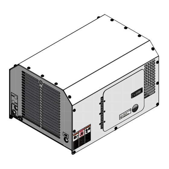
Page 48: Canopy System
Canopy System Parts List ITEM PART NUMBER DESCRIPTION 301383 LATCH 943103-025 RIVET 306891 HINGE 961504-090 981504-075 SCREW 977004-062 WASHER 984004-071 WASHER 306944 SPACER 302011-013 GROMMET 308076 PANEL 308078 PANEL 308079 PANEL 308077 PANEL 309138 HARNESS 3 ft 300444 TAPE, FOAM 309150... - Page 49 Canopy System 309150...
-
Page 50: Decal System
Decal System Parts List ITEM PART NUMBER DESCRIPTION 305761 DECAL, SERIAL TAG 308353 DECAL, SHEET 308353-01 DECAL, DRIVE COUPLING 308353-02 DECAL, DANGER BREATHING 308353-03 DECAL, WARNING CONNECT AIR 308353-04 DECAL, WARNING READ MANUAL 308353-05 DECAL, DO NOT BLOCK AIR INTAKE 308353-06 DECAL, HYD PRESS &... - Page 51 Decal System 309150...
-
Page 52: Wiring Diagram
309150...
Need help?
Do you have a question about the 36 BHP PISTON and is the answer not in the manual?
Questions and answers