
Subscribe to Our Youtube Channel
Related Manuals for LaserPro Spirit SI


Summary of Contents for LaserPro Spirit SI
-
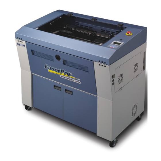
Page 1: Maintenance Manual
Maintenance Manual Spirit SI /GE/GX/LS Distributed & Supported by: Jorlink USA, Inc. | Tel: (336) 288-1613 | support@jorlink.com | www.JORLINK.com 1/60... -
Page 2: Table Of Contents
Spirit SI/GE/GX/LS Maintenance Manual Introduction. Serial number.…...…………………………………………………………..3 Safety Precautions…………………………………………………………..3 Chapter 1. Machine Overview Section 1. Mechanical System Overall…………………………………………………………………..4 Top Cover……………………………………………………………….5 Mid Section……………………………………………………………..6 Base Section…………………………………………………………….7 X-axis Assembly………………………………………………………..8 Y-axis Assembly………………………………………………………...9 Pen carriage……………………………………………………………10 Z-platform……………………………………………………………..11 Mirror 1 / Laser unit…………………………………………………...12 Power Supply………………………………………………………….13 Base section side panel………………………………………………...14 Section 2. - Page 3 How to upgrade Firmware?………………………………………………..31 Chapter 2. System Diagnostics Section 1. Hidden Diagnostics……………………………………………………….32 Chapter 3. Preventive Maintenance Section 1. Cleaning Lenses…………………………………………………………..34 Section 2. Cleaning and protecting the X, Y rails……………………………………37 Section 3. Changing the X rollers……………………………………………………39 Section 4. Changing the X-rail……………………………………………………….30 Section 5.
-
Page 4: Introduction
Introduction 1. Serial Number. The Serial number of your machine is very important and unique. Please copy down the serial number and keep it for your records. Please include this serial number when you correspond with us for any kind of questions. Thank you. 2. -
Page 5: Chapter 1. Machine Overview
Chapter 1. Machine Overview 1. Overall Distributed & Supported by: Jorlink USA, Inc. | Tel: (336) 288-1613 | support@jorlink.com | www.JORLINK.com 5/60... - Page 6 Parts Number for Parts Number for Parts Number for Parts Number Parts Name for LS 29006263G BK01853A 29003643G 29004573G Top cover assembly 29006040G BK01840A 29003676(02) 29004575G X-axis assembly 29005927G BK01832A 29002531 29004576G Y-axis assembly (Left) 29005928G BK01833A 29002532 29004577G Y-axis assembly (Right) 29002548G BK01852A 29003644(01)
- Page 7 2-1. Top Cover for Spirit SI, GE, GX Parts Number for SI Parts Number for GE Parts Number for GX Parts Name ZZ01212A 26500166 26500166G Window hinge PL01801A 22801557 22802102G Window SW00043A 25700035 25700035G Emergency switch SW00045A 25700032 25700032G Lamp switch...
-
Page 8: Top Cover
2-1. Top Cover for Spirit LS ITEM PARTS NUMBER PARTS NAME QTY. 29006263G Top Cover assembly 26500166G Window Hinge 29003833G Window Assembly 25700094G Key Switch 23400020G Control panel sticker 24400995G Key board Key Switch to Emergency Stop 20901927G Switch Cable 29005274G Keyboard Assembly Distributed &... -
Page 9: Mid Section
3. Mid Section Parts number for SI Parts Number for GE Parts Number for GX Parts name & LS BK01804A 29002506 29005033G Spirit main board BK01362C 29001141 29001141G Z motor assembly PW00026A 24500022 24500022G Meanwell power supply 40/5V BK01839A 29002537 29002537G Motor group BK01808A... -
Page 10: Base Section
4. Base Section Parts number for SI Parts Number for SI LS Parts name BK01830A←1 29003272G←1 Base back door assembly BK01824A←2 29003651G←2 12W system Assembly BK01807A←3 29005059G←3 DC12V POWER MODULE BK018B1A←4 29002557G←4 12W power supply fixture BK01823A←5 29003783G←5 12V Power block Parts number for SI Parts Number for SI LS Parts name BK01830A←1... - Page 11 BK01807A←3 29005059G←3 DC12V POWER MODULE BK018B1A←4 29002562G←4 25W power supply fixture BK01823A←5 29003783G←5 12V Power block Parts number for SI Parts Number for SI LS Parts name BK01830A←1 29003629G←1 Base back door assembly BK01824A←2 29004123G←2 V30 system Assembly BK01807A←3 29005059G←3 DC12V POWER MODULE BK018B1A←4 29003971G←4...
-
Page 12: X-Axis Assembly
5. X-axis assembly for Spirit SI/GE Parts number for SI Parts Number for GE Parts name BK01842A 29002540 X axis transmission pulley assembly BL01801A 20600074 X axis belt LH01830A 22800940 X axis mid belt wheel BK01809A 29002511 X motor module... - Page 13 5-1. X-axis assembly for Spirit GX (including lens carriage assembly) Part number for GX Part name for GX 23300265G X axis linear guide 22800673G x axis main beam 22800672G X-axis beam - 1 20700037G bearing 22800823G X-axis pulley core (right) 22800686G X Pulley_30 teeth gear 22800664G...
- Page 14 29004736G Carriage mirror Holder 22802107G Lens carriage base 29004980G SPIRIT GX X-AXIS MOTOR SET 23300298G Hand Knobs(CRKB.M3-6L) Distributed & Supported by: Jorlink USA, Inc. | Tel: (336) 288-1613 | support@jorlink.com | www.JORLINK.com 14/60...
- Page 15 5-2. X-axis assembly for Spirit LS ITEM PARTS NUMBER PARTS NAME 23301231G linear guide(MGN9C1R800Z0CM<E10>) 22803045G x axis slideway 20600176G Open Steel Filum Belt (U2GT-1794-15) 29002537G X motor assembly 29005107G X motor PCB(AAS I) - Spirit 29005506G Lens carriage Assembly 22803049G Tension pulley shaft bracket 29006039G Tension idle pulley Assembly...
-
Page 16: Y-Axis Assembly
6. Y-axis assembly Parts number for SI Parts Number for GE Parts Number for GX Parts name 29005867G 29002531G 29004576G Y-Axis Rail Assembly(Left) 29005866G 29002532G 29004577G Y-Axis Rail Assembly(Right) LH01831A 22800941 22800941 Y axis transmit belt wheel BR01803A 20700054 20700054 Bearing LH01854A 22800950... - Page 17 6-1. Y-axis assembly for Spirit LS ITEM PARTS NUMBER PARTS NAME QTY. 29005927G Y-Axis Rail Assembly(left) 29005928G Y-Axis Rail Assembly(right) 29006390G Y Transmit Shaft Assembly 29002537G Y Motor assembly Distributed & Supported by: Jorlink USA, Inc. | Tel: (336) 288-1613 | support@jorlink.com | www.JORLINK.com 17/60...
-
Page 18: Pen Carriage
7. Pen carriage for Spirit SI/GE Parts number for SI Parts Number for GE Parts Number BK01845A 29002543 Wheel spring assembly BK01836A 29002535 Unilateral wheel LH01814A 22800925 Lens carriage base LH01813A 22801018 Lens carriage organize BK01850A 29002546 Auto focus seat assembly... - Page 19 7-1. Pen carriage for Spirit LS ITEM PARTS NUMBER PARTS NAME QTY. 22802108G Lens carriage roconnect board - 22801996G Lens carriage Assembly-V2 29006010G Auto focus pin Assembly 29002546G Auto focus seat Assembly 29004736G Carriage Reflector Hold 29002545G 2.0" Focal lens Assembly 29002554G 1.5"...
-
Page 20: Z-Platform
8. Z-platform Parts number for SI Parts Number for GE Parts Number for GX Parts name & LS PL01805A 24100366 22802102G Bearing seat BR01301A 20700034 20700034G Bearing LH01810A 22800922 22800922G Z axis top stopper LH01862A 22801022 22801022G Z axis table screw PS01815A 29003638 24402291G... -
Page 21: Mirror 1/Laser Unit
9. Mirror 1/Laser unit Parts number for SI Parts Number for GE/GX Parts name EZ00170B 30W laser tube (depends on model) BK01826A Red pointer assembly BK01827A 3X beam expander BK01326E Red pointer mirror BK01829A Mirror 1 assembly MZ01804A Prism mounts assembly Distributed &... -
Page 22: Power Supply
10. Power supply Parts number for SI Parts Number for GE Parts Number for GX Parts name BK01811A 29002513 29002513G Laser power adapter PW00027A Power supply PSP-600 24500032 24500032G Power supply ASNER 800W 30V Distributed & Supported by: Jorlink USA, Inc. | Tel: (336) 288-1613 | support@jorlink.com | www.JORLINK.com 22/60... -
Page 23: Base Section Side Panel
11. Base section side panel (SI) Parts number for SI Parts Number for GE/GX Parts name SW00024A Rocker switch SW-115 CN00351A AC plug FU00003A Fuse CN00947A AC connector EZ00238A SSR KSD215AC3 PW00039A Power LPS-75-12 DC 12V BK01807A DC 12V module Distributed &... -
Page 24: Section 2. Power System
T-100 24500032 The normal voltage output of the power supply for Spirit SI should be at 48V and for Spirit GE should be at 30V. To measure the output voltage of the power supply unit, use a multi-meter to get the voltage reading at the immediate output location. -
Page 25: Power Supply
10W~25W Power Cable Layout Diagram (SI) AC 100V-AC240V INPUT FUSE ON/OFF Switch Line Filter LASER POWER SUPPLY FUSE FAN&LAMP POWER SUPPLY POWER BOARD Main BOARD Distributed & Supported by: Jorlink USA, Inc. | Tel: (336) 288-1613 | support@jorlink.com | www.JORLINK.com 25/60... - Page 26 50W~75W Power Cable Layout Diagram (SI) AC 200V-AC240V INPUT FUSE ON/OFF Switch Line Filter LASER POWER SUPPLY FUSE FAN&LAMP POWER SUPPLY POWER BOARD Main BOARD Distributed & Supported by: Jorlink USA, Inc. | Tel: (336) 288-1613 | support@jorlink.com | www.JORLINK.com 26/60...
- Page 27 100W Power Cable Layout Diagram (SI) AC200~AC240V INPUT Relay ON/OFF Switch Switch FUSE FUSE Line Filter Line Filter LASER POWER SUPPLY FUSE FAN&LAMP POWER POWER SUPPLY BOARD Main BOARD Distributed & Supported by: Jorlink USA, Inc. | Tel: (336) 288-1613 | support@jorlink.com | www.JORLINK.com 27/60...
- Page 28 Section 3: Electrical System SPIRIT MAINBOARD DIAGRAM Working Table Stepping Motor UV SENSOR AutoFocus PCB Door Switch X- Motor Y- Motor Rotary Attachment Control Panel Y-MOTOR PCB X-MOTOR PCB Power (40V/5V) Power FLASH Parallel Port SRAM Limit Switch USB Port Buzzer Control Reset LED...
-
Page 29: Laser Power Adaptor
BK1807A DC12V Module BK01811A Laser Power Adaptor Distributed & Supported by: Jorlink USA, Inc. | Tel: (336) 288-1613 | support@jorlink.com | www.JORLINK.com 29/60... -
Page 30: Control Panel
Control Panel Dial for adjusting contrast. Load firmware button. (Button is at lower position at default.) Distributed & Supported by: Jorlink USA, Inc. | Tel: (336) 288-1613 | support@jorlink.com | www.JORLINK.com 30/60... -
Page 31: Section 4. Laser System
Section 4: Laser System What is laser? Laser is an acronym from Light Amplification by Stimulated Emission of Radiation. Types of laser tubes There are two types of laser sources used with the Spirit, namely Coherent-Deos and Synrad. There are 12W, 25W, 30W, 60W and 100W models with Synrad laser tubes and also there are 30W, 40W, 60W, and 100W models with Coherent Deos laser tubes. -
Page 32: Optical Alignment
How does the laser beam travel to the working area? The laser beam generated by the laser source is reflected and guided by 4 optical lenses on to the working area. Therefore the proper adjustment and maintenance of them are crucial. Optical Alignment Understanding Reflection. - Page 33 Step 2: Place a piece of masking tape over the tube opening that leads to Mirror 2. Fire the laser and see if it leaves a burnt mark in the center of the hole. Also check that the burnt mark left by the laser beam is circular in shape.
- Page 34 Step 4: Place a masking tape on the opening before Mirror 4. Move the pen carriage to the upper left corner of the working area. Fire the laser and adjust Mirror 3 so the laser beam passes through the center of the opening. Move the pen carriage to the upper right end of the working table.
- Page 35 10W~25W Laser Tube Wiring Diagram (SI) AC 110V/220V DC Power Supply 30V DC 30V POWER PCB 10W~25W Laser Tube Distributed & Supported by: Jorlink USA, Inc. | Tel: (336) 288-1613 | support@jorlink.com | www.JORLINK.com 35/60...
-
Page 36: Laser Tube Wiring Diagrams
30~40W Laser Tube Wiring Diagram (SI) AC 110V/220V Power Power Supply Supply DC 48V POWER PCB 30W~40W Laser Tube Distributed & Supported by: Jorlink USA, Inc. | Tel: (336) 288-1613 | support@jorlink.com | www.JORLINK.com 36/60... - Page 37 50W~75W Laser Tube Wiring Diagram (SI) AC 110V/220V Power Power Power Supply Supply Supply DC 48V POWER PCB 50W~75W Laser Tube Distributed & Supported by: Jorlink USA, Inc. | Tel: (336) 288-1613 | support@jorlink.com | www.JORLINK.com 37/60...
- Page 38 100W Laser Tube Wiring Diagram (SI) AC 220V Power Power Power Power Power Supply Supply Supply Supply Supply DC 48V POWER PCB 100W Laser Tube Distributed & Supported by: Jorlink USA, Inc. | Tel: (336) 288-1613 | support@jorlink.com | www.JORLINK.com 38/60...
-
Page 39: How To Upgrade Firmware
Section 5: Firmware How to upgrade the firmware? From www.gccworld.com website, you can logon with a distributor account and download an utility tool called “uploader.exe” With this utility tool you can upgrade the machine to the newest firmware or the firmware of your choice. 1. -
Page 40: Chapter 2. System Diagnostics
Chapter 2. System Diagnostics Section 1. Hidden Diagnostics To enter the hidden Diagnostics menu, hold down the Autofocus button and turn on the machine. There are 11 tests under the hidden diagnostics menu. LCM Key Test LCM Key test will test the functionality of the keys on the keypad. LCM Interface Test LCM Interface test will display a series of different shapes on the LCM to allow user to detect any malfunction on the display unit. - Page 41 utility that you use to perform beam alignment.) X motor test X motor test checks that the X motor is functional by asking user to use the keys on the control panel to move the pen carriage along the X axle. Y motor test Y motor test checks that the Y motor is functional by asking user to use the keys on the control panel to move the pen carriage along the Y axle.
-
Page 42: Chapter 3 Preventive Maintenance
Chapter 3 Preventive Maintenance 1. Cleaning of optical lenses In order to prolong the usability of the optical lenses, it is recommended that we clean the optical lenses once every week or as required. Since these lenses are coated with a chemical substance that protects the lens itself from the intensive laser power, we have to take great care when cleaning the lenses so that we do not scratch or peel off the chemical substance. - Page 43 Cleaning the optical mirrors: Release the screws holding the mirrors in place. Place a piece of lens cleaning paper and add a drop of lens cleaning solution. Slowly pull the wetted paper from one side to another. Make sure the lens is cleaned, dried and does not have any debris on the surface. Cleaning the focusing lens: First remove the lens from the pen carriage.
-
Page 44: Section 2. Cleaning And Protecting The X, Y Rails
three screws on the pen carriage as shown below and locate the focusing lens in the pen carriage. Apply a drop or two of the cleaning solution on a cotton bud and lightly clean the focusing lens. Use a second cotton bud to dry or air dry the lens. Make sure the lens is clean and dried before putting it back in the pen carriage unit. - Page 45 corroded. It is recommended that the X-rail should be cleaned daily or after each day’s operation. The Y-rail requires the same type of cleaning and greasing about once a week. Use a piece of non-abrasive cloth to swipe and clean the rails. Then apply a small amount of the PS2 grease on to the rail and swipe it clean again.
- Page 46 Distributed & Supported by: Jorlink USA, Inc. | Tel: (336) 288-1613 | support@jorlink.com | www.JORLINK.com 46/60...
-
Page 47: Section 3. Changing The X Rollers
3. Changing the X rollers The estimated life of a set of rollers is about 500 working hours. To change rollers, simply remove the hex bolts using a size 3 Allen key as shown below. Notice that the roller has a wider side and a narrower side. The narrower side should be closer to the pen carriage. - Page 48 Distributed & Supported by: Jorlink USA, Inc. | Tel: (336) 288-1613 | support@jorlink.com | www.JORLINK.com 48/60...
- Page 49 4. Exchanging the X-axis assembly Remove the screws shown below to remove the cover. After removing the cover, disconnect the transparent air pipe and the X-motor flat cables as shown. Remove two hex bolts on each side of the X-axis. Distributed &...
-
Page 50: Section 5. Changing The Y Rollers
Then lift up the X-rail assembly to detach from the mounts. 5. Changing the Y rollers. Detach the X-rail and remove the following screws to completely remove the Y roller holders. Distributed & Supported by: Jorlink USA, Inc. | Tel: (336) 288-1613 | support@jorlink.com | www.JORLINK.com 50/60... - Page 51 Unscrew the following screws to remove the side rollers. Distributed & Supported by: Jorlink USA, Inc. | Tel: (336) 288-1613 | support@jorlink.com | www.JORLINK.com 51/60...
-
Page 52: Section 1. Error Messages
Chapter 4. Troubleshooting Section 1. Error messages Error Message What does it mean? What to do? "Laser Tube Error Laser This means that the laser 1. Turn off the machine to tube is over heat please tube’s temperature is too allow the laser tube to press any key to stop."... - Page 53 please move opposite 2. Check that the Z-limit direction" switch sensor is working properly. 3. Continue work or lower the Z-platform if necessary. "PCL Command Error The firmware on the 1. Find out the firmware Command: Address: machine and the application and driver versions that Please press any key to driver is not compatible.
- Page 54 "No Flash Memory. Please The flash memory is not 1. Make sure that the flash check the device on detected. memory is installed machine." properly. 2. Save file again. "X motor malfunction. For X-motor failed or its related 1. Turn off the machine. service please inform your components failed.
- Page 55 fixed. 6. If error remains after the Y-motor change, replace the main board as well. "Z motor malfunction. For Z-motor failed or its related 1. Check that the service please inform your components failed. connections of the local distributor" wiring are not loosed or damaged.
-
Page 56: Section 2. Error Lights
Section 2. Error lights Identifying problems by looking at the lights on the mainboard. The LED circled in green is the 5V light. This light should always be “ON“ showing that there is a 5V supplied to the mainboard. Check that the power supply next to the mainboard that provides the 5V power is working properly if it is not “on”. - Page 57 The LED circled in blue is the reset light. This light should only turn on when the reset button is hit. If it stays “on” all the time then the mainboard needs to be changed. The LED circled in yellow is the initialization light. This light turns on when the machine is turned on.
- Page 58 When the first LED from the left turns “ON”, check that the RF cable is connected. When the third LED from the left turns “ON”, either the laser head or the RF cable is bad. When the fifth LED from the left turns “ON”, the RF power supply has gone over temperature.
- Page 59 During initialization, the sixth LED from the left will turn “on” by default. The LED will turn “off” after the initialization meaning that the laser is ready to fire. However, if the LED stays on afterwards, that means the laser source is malfunctioning.
- Page 60 Start/Stop key to save and restart the machine. Distributed & Supported by: Jorlink USA, Inc. | Tel: (336) 288-1613 | support@jorlink.com | www.JORLINK.com 60/60...
Need help?
Do you have a question about the Spirit SI and is the answer not in the manual?
Questions and answers
Hello, my laser tube status lights are not coming on at all. Also my LCD screen is blank. It's backlite, but no wording. There's a red beam of light but no laser at the head. All the other lights on the main board seem to be operating correctly. Safety switches are all closed too. GCC Laser Pro Model number ME-25 Serial Number N95590