Table of Contents
Advertisement
Advertisement
Table of Contents

Related Manuals for LaserPro Mercury


Summary of Contents for LaserPro Mercury
-
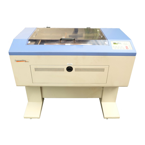
Page 1: User Manual
USER MANUAL MERCURY... - Page 2 Serial Transmission................20 Interface for Macintosh ..............20 Exhaust Ventilation................20 IV. SOFTWARE INSTALLATION ......... 21 Install LaserPro Mercury driver to PC ...........21 V. OPERATION ..............21 Environment ..................21 Flexible Utility of Your Memory Buffer ...........21 Am I in Multiple File mode or Single File mode now? ....22 Start to Operate.................23...
- Page 3 VII. TROUBLE SHOOTING ..........64 Quality Problems ................64 Non-operational Problems ..............64 Appendix A. 3D Function ............65 Tip for 3D Application...............65 APPENDIX B. Application Parameters ....... 67 Engraving Parameter...............67 Cutting Parameters ................68 APPENDIX C. Specification ..........69 Optional Items:..................69...
-
Page 4: Quick Menu
Setup computer and connect with engraving system properly. Turn ON host computer system. Install the MERCURY Driver. (for the first time use only) Use Windows-based program (such as CorelDraw, PhotoShop, PhotoPaint, Illustrator, CASmate, Signlab, EasySign, AutoCAD, etc.) to operate with the engraver. - Page 5 NOTICE: 1. In order to match Mercury driver’s color. Make sure your CorelDRAW V.11 or later the “Color Management off” is disable. Please fallow the steps: Tools Color Management Color Management Off 2. When operating with CorelDRAW V.11 or later version, please choose Layout Page Setup Set From Printer.
-
Page 6: I. Introduction
In addition to the safety features of a Class1 machine, the LaserPro Mercury has been equipped with a red guidance pointer. This red dot allows the operator to safely see the focal point of the laser beam. It also gives Mercury the improved CDRH safety rating of 3R. Precaution 1. -
Page 7: Warning Label
The Safety Interlock System The LaserPro EXPLORER is complete with a safety interlock system that automatically shuts off the power supply to the laser whenever the top or front door is opened. There are magnets on the top and front door, which activate this safety mechanism. Do not attempt to remove or modify these magnets or any other component of the safety interlock system. -
Page 8: Frequently Asked Questions
Mercury? The maximum engraving speed of LasePro Mercury is 1066 mm/sec (42 inch/sec). When engraving an A4 (18 x 28 cm) size square with 250dpi at full speed, it takes LaserPro Mercury about 18 minutes to complete. 6. How to engrave an extremely long working piece? - Page 9 screws. For a better ventilation and safe purpose, this special design is to prevent the back door being opened without notice during operating. However, you have to use magnetic devices to short the connector of the magnetic switches on both side of the front door while opening for engraving extremely long work-piece.
- Page 10 Front Vie Top Door Switches & Ports Control Panel Top Door Front Laser Source Door Press the ring to pull Control Panel out the air tube. Valve Air inlet connect Air Flow to air compressor Fixer Front Laser Source Press the ring to pull out the air tube.
-
Page 11: Back View
Back View Top Door NOTE: Please refer to Fig. 25 and follow the instruction for the basic maintenance of mirror. Step 1 Step 2 Step 3 Unscrew and Disassemble remove the Unscrew and to maintain Unscrew and panel. #1 mirror. remove the pull out Laser... - Page 12 Dust Prevention Box (Mirror 2 inside) Mirror 3 & Holder Release the Screw to Pull Mirror 4 and Focus Lens inside Out the Mirror Y-axis Belt X-axis Bearing X-axis Motor X-axis Belt Bearing Track Y-axis Belt Manual Focus Gauge Holder Focal-Sharp™...
-
Page 13: Lens And Manual Focus Gauge
Lens and Manual Focus Gauge Focal Length Matched Color LENS MANUAL FOCUS GAUGE 1.5” Option Purple Blue (same as 2.0”) 2.0” Standard Blue Blue 2.5” Option Gold Gold 4.0” Option Manual Focus Gauge Insert to the hole of the holder for manual focusing Mirror Lens 2.0, 2.5 or 4.0... -
Page 14: Instruction Of Rotary Attachment
Instruction of Rotary Attachment 1) Turn off the power of the engraver. 2) Put the rotary attachment onto the engraving table. Ensure the two screw holes should match the two corresponding holes on the table and the white mark of the left side align to the position of 24cm (9.45 inch) on the ruler, then tighten the screws. -
Page 15: Top View
TOP VIEW ruler track lever White Mark port Screw Holes Window Operation: NOTE: The maximum length of the engraving object is 450 mm (17.71 inch). maximum diameter of the padded rubber wheel is 94 mm. To get an accurate engraving position during rotating, it is better that the diameter of the engraving object is not smaller than 90mm (3.54 inch). -
Page 16: Side View
6. The following is an example of engraving process by using CorelDRAW V.11 or after version a. File b. Print Setup, choose MERCURY c. Properties d. Paper, select Rotary Fixture e. key in Offset value, X value and Diameter value... -
Page 17: Dual Head Installation
Dual Head Installation Step 1:Turn off the system. Step2:Put the dual head carriage onto the X-axis belt bearing track. Step3:Cut 25mm (1 inch) off the air assist tube on the original lens carriage. Step4:Connect the air assist tube of the dual head with that of original carriage by “T” connector. - Page 18 1. Keep the screws on the lens carriage after taking off the dual head. 2. Put the black cap on the “T” connector after taking off the dual head to prevent air flowing leaking. 3. Please choose dual head item from Paper option of printer properties before outputting a graph with dual head carriage.
-
Page 19: Ii. Recommended Configuration
II. RECOMMENDED CONFIGURATION Computer Your PC must be sufficient to equip with Window 95 at least. We recommend the specification of PC for better work as following. Pentium at least DRAM 32 MB RAM or up One 3.5" 1.44 MB floppy 1.2 GB Hard Drive or up SVGA 15"... -
Page 20: Iii. Hardware Installation
III. HARDWARE INSTALLATION Caution: Turn all equipment off before making any connection. Check the plug of the power cord to see if it matches the wall outlet. If not, please contact your dealer. Cabling Connection: 1. Insert the power cord (male) into a grounded power outlet. 2. -
Page 21: Serial Transmission
Serial Transmission If you are using IBM PC, PS/2 or their compatibles, connect the supplied RS-232C cable to the engraver (serial port) then to the serial port of the host computer. Interface for Macintosh To operate the engraver with a Macintosh computer (e.g. Power Mac), you need a MAC modem cable (DIN8 to DB25) as an adaptor to connect to the RS-232C cable. -
Page 22: Iv. Software Installation
Have a fire extinguisher available at any time. Flexible Utility of Your Memory Buffer The standard memory buffer size of Mercury is 16M and can be expanded to 64M ( 32M SIMM x 2). You can choose Multiple file mode with limited memory to save files and re-call them for constant applications. -
Page 23: Am I In Multiple File Mode Or Single File Mode Now
Am I in Multiple File mode or Single File mode now? Power ON LaserPro MERCURY Firmware V x. xx Copyright 200x Initializing Please wait Table moves down about 50mm. Press FUNCTION key. Set memory buffer? Yes: ENTER End operation: ESC... -
Page 24: Start To Operate
Start to Operate Power ON LaserPro MERCURY Firmware V x. xx Copyright 200x Initializing Please wait Table moves down about 50mm automatically Single file status Multiple file status Under STARTcondition Upon the receipt of files, start to Under STOP engrave/cut... -
Page 25: Start/Stop
START/STOP Single File Mode: Turn on power, MERCURY is under START condition and ready to receive a file. LCD shows as follows: File: Speed: Power: DPI: Copies 1 Upon the receipt of a file, MERCURY starts to engrave/cut immediately. When a job is done, LCD will show the working time such as 01:10 means 1minute and 10 seconds. - Page 26 Upon the receipt of a complete file, LCD will show the following message for instance. Then press START/STOP key, the engraver starts engraving or cutting. File: # 1 file name Speed: 70 % 00:00 Power: 40 % PPI: xxxx DPI: If there is no file having been sent, the message will display as follows.
- Page 27 Set up laser speed for desired effect. When working without using MERCURY’s driver, lower case press FUNCTION key then select one of the sixteen setups then set up desired cutting speed. No matter you are using MERCURY’s driver or not, you can change speed on the fly by...
- Page 28 pressing PAUSE key prior to change speed during cutting or engraving. Set up desired speed, press ENTER then press RESUME to continue the job. POWER Set up laser power for desired depth and effect. Other conditions are same as stated in SPEED.
-
Page 29: Function
FUNCTION Set memory buffer? Setting memory buffer in Single file mode when working with a large data file, or Multiple file mode (up to 100 files) that can be saved for constant engraving. Under Single file mode, you can only output one job a time. Unlimited data can be transferred without saving in the buffer therefore once you want to repeat the job you have to re-send the file from the host computer. - Page 30 Z init/AF position? To avoid focus carriage hitting the engraving object accidentally during initializing, working table will move down about 50mm automatically after power on the equipment. Whereas, if a rotary attachment has been installed, the working table will move down to the bottom of the engraver.
- Page 31 Delete all files? All files in the buffer will be deleted by using this function when setting under Multiple file mode. This function is invalid under Single file mode. Once you stop or complete a job under Single File mode the file won’t be saved in the buffer. Delete all files? Ok: ENTER End operation: ESC...
- Page 32 Select lens? There are four different lenses for use on the LaserPro MERCURY as follows: Focal Length Resolution Cutting capability 1.5” optional High Thin 2.0” standard 2.5” optional Thick 4.0” optional The high resolution lens is designed for precision engraving, while the low resolution lens is mostly applied for cutting due to its lower beam divergence which results in a straighter cut in thick materials.
- Page 33 Set power ramp? If set in Enable condition and cutting speed is 3% or above, under vector mode, the power control is enabled. If set in Disable, the power control is disabled. Default : Enable Set power ramp? Yes: ENTER End operation: ESC Select unit? : ENTER...
- Page 34 Select unit? Set unit in Metric or English. Select unit? Yes: ENTER End operation: ESC Set EOF alarm? : ENTER Metric (mm)** Ok: ENTER Change: △ or ▽ △ or ▽ English (inch) Ok: ENTER Change: △ or ▽ ENTER Set EOF alarm? Yes: ENTER End operation: ESC...
- Page 35 Set EOF alarm? If set in Enable condition, a beep tone sounds when End OF File. Set EOF alarm? Yes: ENTER End operation: ESC Tune Autofocusing? : ENTER Enable** Ok: ENTER Change: △ or ▽ Change: △ or ▽ Disable Ok: ENTER Change: △...
- Page 36 Tune (Auto focusing)? In case the focal length of auto Focus needs to be corrected, please insert the corresponding manual focal tool to the hole of the holder shown as in the Figure of LENS and MANUAL FOCUS GAUGE. Then, operate as follows. Tune (Autofocusing)? Yes: ENTER End operation: ESC...
- Page 37 Select setup #1-16? You can assign 16 different colors individually for speed and power to achieve a variety of cutting effects. This function works when your software package can output HPGL plot without using MERCURY’s driver. Select setup #1-16? Yes: ENTER...
- Page 38 NOTE: ** means default or current setting. Select baud rate? Baud rate is to determine the speed of data transmission of serial port to communicate with the host computer. Setting range: 9600, 19200, 38400, 57600 Defaults: 57600 Select baud rate? Yes: ENTER End operation: ESC Data bit/parity? :...
- Page 39 Set data bit/parity? Data bits refer to the size of one block of data and parity is used to check if data was received correctly or not. The data/parity feature is to adjust the byte format and parity type in order to communicate with the host computer through serial port.
- Page 40 Select language? Select language? Yes: ENTER End operation: ESC ENTER English Ok: ENTER Change: △ or ▽ △ or ▽ English Polish xxxxxx Italian Japanese Ok: ENTER Deutsch Turkish Change: △ or ▽ ENTER or ESC Multi file mode Single file mode Do setup or press Do setup or send at STAR key then send...
-
Page 41: Software Operation
Software Operation Editing Jobs A. CorelDRAW Page Size Setting Please ensure the laser engraver is set as the Default Printer before following the next steps. Step1: Click Layout → Page Setup Step2: Set From Printer Step3: Click the page size to be the same as the printer’s paper size. (Ensure the Normal Paper and Layout options are checked.) Step4: Click OK to complete the page size setting. - Page 42 Step5: Check the Page Size has changed...
- Page 43 B. Vector Cutting The laser cutting is NOT doing a proper cutting, because the width of the text’s outline is not set to its thinnest width. The MS-Windows® driver determines raster engraving or vector cutting based on the outline width of an object. Therefore to achieve a vector cutting, please set the text’s filled with white color and the outline to its thinnest width in CorelDraw.
- Page 44 3. Change the text’s outline color by right clicking on the desired color on CorelDraw Color Palette. Notice If the width of the line to be cut is not set at minimum value, the laser is going to performing etching instead of vector cutting. The laser unit looks like engraving from left to right and right to left instead of cutting.
- Page 45 4. Change the outline to its thinnest width by right clicking on the selected text 5. Go to the “Properties” option 6. Click on the “Outline” tab and change the “Width” to its thinnest dimension.
- Page 46 7. Click on “OK” to apply the changes. 8. Print out the selected text again and the laser will do the letter cutting. C. Raster Engraving Laser engraver prints raster as grids or dots of individually pixels, any digital or scanned images can be processed by a laser engraver.
- Page 47 Printing – Mercury Driver Editing After completing the editing job, choose File → Print and click “Properties” to access Mercury driver parameter settings.
- Page 48 (power & speed setting). The Mercury driver will interpret colored and shaded areas as different shades of gray / halftone areas, and it is a collection of dots. The resolution and depth of these halftone areas...
- Page 49 a. Dot: A halftone pattern consists of circle dots. b. Corner: The dark dot spread from the left upper corner of the pattern result in a little triangle shape to imitate a shading effect. c. Bayer : A random halftone pattern. d.
- Page 50 45 degree+ 10*10 dithering A-2 Manual Color Fill Mode Each power and speed setting can be linked to certain color on the layout. Totally 16 color settings are available. The desired color can be adjusted by changing the ratio of Red, Green and Blue.
- Page 51 Pitch Value & Shoulder Power Setting The finished stamp will be a reversed image with engraved depressions and ridges. Many of these ridges may be too thin and would break off or be unstable. Creating pitch is a way to add support to the thin lines and ridges. The pitch value setting allows you to adjust the width of the ridges.
- Page 52 The central part presents the letter of stamp. The blue bar means different laser power level to compose of the slope. Higher level blue bar gets less engraving laser power. Power Level of Stamp Mode This function is to adjust the power distribution of the slope shoulder to get the better shape of stamp’s vertical profile.
- Page 53 After you have created a border around the stamp, you may wish to have the Mercury’s vector setting cut out the stamp from the rubber sheet. To do this, create a thin (0.001”) red line around the outline edge of the border or where ever you wish the stamp to be cut.
- Page 54 B. Parameter Settings The LaserPro Mercury allows the use of 16 different colors to represent 16 different power and speed settings when cutting and engraving. These colors are referred to as PENS. Try to think of each pen as a designated laser setting, rather than as a color. An image that is only black and white will use only one power and speed laser setting (Black).
- Page 55 distinct areas. The speed and power settings designated to each pen color, will represent a proportion of the master control speed and power settings. If you would like to use a color not included in the driver’s original 16 colors, please double click on the specified pen and the color manager window would jump out then you can select the color you would like to apply.
- Page 56 Lower DPI settings will have coarser and shallower engraving, but will take less time to complete. Experiment with different settings to get your desired effect. You can find the DPI function at Mercury driver-> Properties-> Option.
- Page 57 These editing options can be saved in image files such as CoreI Draw graphics with printer driver parameters setting inside or can be saved a s the default settings in Mercury driver for future files. Please make sure your ID to log in the computer is set to “Administrator ” level, therefore OS of 2000/XP can allow you to save parameter settings.
- Page 58 NOTE: If you wish to use Border and Cluster, then the border must be less than the distance specified in the Cluster setting. C. Advance Setting C-1 Scaling Scaling function enables you to adjust output inaccuracy when you find the actual output scale is different from what you set in the computer, you can use scaling function to modify it and get a perfect one.
- Page 59 C-3 Image Output Direction Top to Bottom – The laser would engraver from top to bottom of the image. Bottom Up – Normally, the LaserPro Mercury engraves from top to bottom, left to right. Selecting Bottom Up will force the machine to start from the bottom and work its way to the rear of the working table.
- Page 60 Add border origin D. Paper Settings These settings are included in Mercury driver Properties → Paper. They are used to adjust several output settings. D-1 Paper Size As described in Paper and Layout Settings, ensure that the paper size is no greater than the working table area.
- Page 61 D-3 Rotary Attachment Rotary attachment is specially designed for engraving on the surface of round objects or cylinders. Please check the chapter of rotary attachment installation in chapter I INTRODUCTION. Diameter: Set up the diameter of the engraving area. Circumference = Diameter x 3.14159 Offset: The distance from the open end of the engraving object to the base of the padded rubber disk.
-
Page 62: Vi. Basic Maintenance
VI. BASIC MAINTENANCE Caution: Keeping the optics and motion system clean is essential to an excellent quality engraving and the reliability of your engraver. Please clean Bearing track and X-axis (DU) bearing daily to maintain good condition of machine. Never pour or spray any liquid directly onto the laser system. Turn off the power and unplug the system before cleaning. - Page 63 Pull the tissue one direction gently after the cleaner has been absorbed Lens Cleaner evenly ○ (CORRECT) Lens Tissue ○ (CORRECT) Do not use cotton swab to rub clean the mirror ╳ (INCORRECT)
-
Page 64: Clean The Focus Lens
Top Screw Mirror Remove Front Cover Loading hole for manual focal tool Auto-focus gauge Focal-Sharp™ Clean the focus lens – 1. Unscrew and remove the front cover of the focus carriage. Pull out focus lens carefully. 2. Flood the focus lens with lens cleanser on both sides then using a cotton swab or lens tissue to dry off the remaining solution gently. -
Page 65: Vii. Trouble Shooting
VII. TROUBLE SHOOTING Quality Problems Check focus length set under the function key to see if it matches the type of the lens installed. Focus Lens is not installed correctly. Focus Lens is loose in the holder. Debris or dust builds up in the bearing tracks or X-Axis rails. The focus lens and the mirror in the carriage are damaged or need to be clean. -
Page 66: Appendix A. 3D Function
Appendix A. 3D Function Tip for 3D Application When doing 3D sample on LaserPro Mercury (L-25), acrylic or MDF wood are ideal materials for the purpose. For acrylic the suggested PWR is 100%, SPD around 30%(depends on how deep you want to cut). - Page 67 3D engraving / Material: 1cm Acrylic by Mercury 25W Lens: 2 inch Step Speed Power DPI PPI Focus Remarks 100% 600 auto Auto Focus 3D Mode Engraving 100% 600 auto Lower down table 2.5mm 3D Mode Engraving 100% 100% Lower table again 2 mm Black and White Mode Polishing 0.2%...
-
Page 68: Appendix B. Application Parameters
APPENDIX B. Application Parameters Engraving Parameter Material LaserPro Power% Speed% Acrylic L-12 L-25 L-50 Laminated Acrylic L-12 L-25 L-50 Immitation Leather L-12 L-25 L-50 Leather L-12 L-25 L-50 Mat Board L-12 L-25 L-50 Padauk L-12 L-25 L-50 Sign Vinyl L-12... -
Page 69: Cutting Parameters
Cutting Parameters Material LaserPro Power% Speed% Acrylic L-12 L-25 L-50 L-12 L-25 L-50 L-12 L-25 L-50 L-12 L-25 L-50 L-25 L-50 12mm L-25 L-50 Rubber 2.5mm L-12 L-25 L-50 Backlite L-12 L-25 L-50 Plywood L-12 L-25 L-50 L-12 L-25 L-50... -
Page 70: Appendix C. Specification
APPENDIX C. Specification MERCURY L-12 L-25 L-40 Laser Source Air Cooled, Sealed CO laser Work Area 25” × 18” (635mm × 458mm) Max. Working Piece 31.5” × 22.4” × 6.5” (800mm × 570mm × 165mm) (all doors closed) Max. Working Piece 26.8”×...
Need help?
Do you have a question about the Mercury and is the answer not in the manual?
Questions and answers