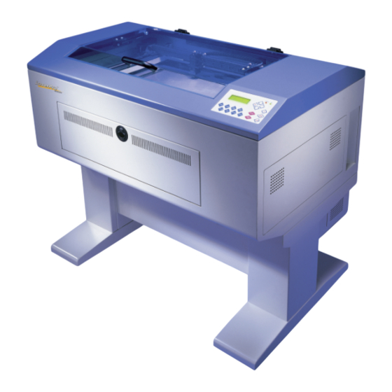
Summary of Contents for LaserPro Mercury
- Page 1 Mercury Beam Alignment Copyright Koser Enterprises, Inc 2006 Member of the LaserProNA.com group Rev 1.00002 Remember to always wear safety glasses while doing any open beam tests.
- Page 2 This document will show you how to check and align your Mercury LaserPro. The first thing to do is to check the alignment. Briefly the logic is to have a perfectly straight beam path from Mirror 2 (Back top left) to mirror 3 (Left end of X axis). From mirror 3 to mirror 4 (the one in the lens carriage).
- Page 3 After the unit initialize the Display will look like this. Press the function Key and wait for the RAM test. It will take only a couple of seconds. Press the right arrow (2) until the display looks like this. Press the Down Arrow (3) until the display looks like the one below. Power should now read 5% You are now ready to check your beam alignment.
- Page 4 Back Side of Mirror 3 Small burn mark Figure 2 Position X axis to P2 (Bring it all the way forward) Put a small pen mark to the side of this dot so you will know which dot was fired first. Repeat steps in Blue to create second dot.
- Page 5 Tools required Philips and Standard Screw driver Offset ratchet standard screw driver. I bought mine at OSH Sears sells them as well as most hardware stores, It would now be a good time to remove the lid. Remove the 8 phillips head screws that hold the lid to the chasse.
- Page 6 Position the machine so that you can access all 4 sides. Tape the acrylic lid closed and remove entire lid. Lean the lid against the right side of the machine so that the Ribbon Cable can be plugged back in. It is keyed and can only be plugged in one way.
- Page 7 If your results are not similar to the above you will need to adjust mirror 2 so that only 1 burn mark and the red dot are visible on the test tape.. Mirror 2 Back of Mercury Mirror 4 Mirror 3...
-
Page 8: Lock Screw
Once you have adjusted the prism mount run the P2 burn again. If it lands on top of your original P1 burn your done. If not re-adjust to correct. You may wish to use a new piece of tape and run P1 and P2 again. - Page 9 Remove the lens form the lens holder. Place a piece of tape on the bottom of the air nozzle. Rub it to leave an impression of the opening. Make sure you remove the tape from the side of the carriage and fire for 1-2 seconds. Remove the tape from the bottom of the air nozzle.
- Page 10 Next remove the small vent plate on the left side, bottom, of the machine (Figure 7) and remove the two thumb screws and the black mirror cover (figure 8). Figure 7 Figure 8 Red Beam Mirror 1 Mirror 0 Remember to always wear safety glasses while doing any open beam tests.
- Page 11 Adjust screws 1 and 3 only on any prism mount. One will be front to rear, while the other will be left and right. Mirror 1’s prim mount is displayed below. Adjust the prism mount of Mirror 1 to move the burn mark into the center of the air funnel below the lens Screw 1 Pivot Screw Screw 2...
- Page 12 To align the Red Beam adjust the prism mount for mirror 0 so that the red dot hits the burn mark on the tape on the bottom of the air assist nozzle from your final test of mirror 1’s adjustment. Mirror 1 Mirror 0 Last but not least follow the direction on how to reset origin.


Need help?
Do you have a question about the Mercury and is the answer not in the manual?
Questions and answers