Roberts Gorden EP-100 Installation, Operation & Service Manual
Hide thumbs
Also See for EP-100:
- Brochure & specs (2 pages) ,
- Installation, operation & service manual (36 pages)
Table of Contents
Advertisement
Quick Links
WARNING
Improper installation, adjustment, alteration, service
or maintenance can result in death, injury or property
damage. Read the Installation, Operation and Service
Manual thoroughly before installing or servicing
this equipment.
Installation must be done by a contractor qualified
in the installation and service of gas-fired heating
equipment or your gas supplier.
Quality in Any Language™
© Copyright 2006 Roberts-Gordon
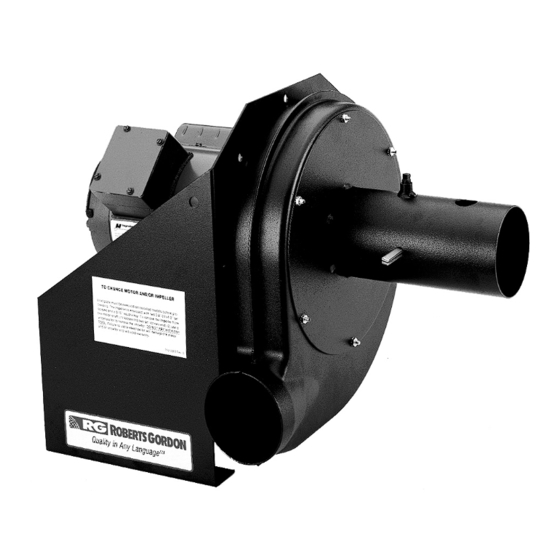
EP-100 Pump
IRHS-VP-100
Please take the time to read and understand
these instructions prior to any installation.
Installer must give a copy of this manual to the owner.
Keep this manual in a safe place in order to provide
your serviceman with necessary information.
Roberts-Gordon, LLC
1250 William Street
P.O. Box 44
Buffalo, New York 14240-0044
Telephone: 716.852.4400
Fax: 716.852.0854
Toll Free: 800.828.7450
www.rg-inc.com
Installation,
Operation &
Service Manual
Installer
Owner
P/N 127201NA Rev. C 06/06
Advertisement
Table of Contents

Subscribe to Our Youtube Channel
Related Manuals for Roberts Gorden EP-100


Summary of Contents for Roberts Gorden EP-100
- Page 1 EP-100 Pump IRHS-VP-100 Installation, Operation & Service Manual WARNING Installer Please take the time to read and understand Improper installation, adjustment, alteration, service these instructions prior to any installation. or maintenance can result in death, injury or property Installer must give a copy of this manual to the owner.
-
Page 3: Table Of Contents
SECTION 10: Replacement Parts and Accessories .20 10.1 Replacement Parts .........20 SECTION 11: Specifications ........21 11.1 Material Specification ........21 ® SECTION 12: The ROBERTS GORDON EP-100 SERIES PUMP Limited Warranty..23 © 2007 Roberts-Gordon, LLC All rights reserved. No part of this work covered by the copyrights herein may be reproduced... - Page 5 Figure 3: Pump Assembly ..........7 Figure 4: Damper Assembly..........8 Figure 5: Motor Shaft Seal Installation ......9 Figure 6: EP-100 Mounting - Chain Suspension ...10 Figure 7: Wall Bracket Assembly........11 Figure 8: Wall Mounting Angle Assembly .....12 Figure 9: Wall Mounting ..........12 Figure 10: Optional Platform Assembly Mounting ..13...
-
Page 7: Section 1: Heating System Safety
SECTION 1: H EATING YSTEM AFETY SECTION 1: HEATING SYSTEM SAFETY Your Safety is Important to Us! This symbol is used throughout the manual to notify you of possible fire, electrical or burn hazards. Please pay special attention when reading and following the warnings in these sections. -
Page 8: Section 2: Installer Responsibility
EP-100 P NSTALLATION PERATION AND ERVICE ANUAL SECTION 2: INSTALLER RESPONSIBILITY The installer is responsible for the following: 2.1 Corrosive Chemicals CAUTION • To install the pump and electrical supplies, in accordance with applicable specifications and Do not use heater and pump in an area containing codes. -
Page 9: Section 3: Unpacking The Pump
SECTION 3: U NPACKING THE SECTION 3: UNPACKING THE PUMP 3.1 Open Shipping Cartons Open cartons and remove packing inserts. Carefully remove pump components from the cartons. Lift assembly by gripping metal pump frame. Two people are required (weight 62 lbs, 28.1 kg). This pump has been tested prior to packing. -
Page 10: Section 4: Major Components
ANUAL SECTION 4: MAJOR COMPONENTS FIGURE 1: Major Component Descriptions Pump Scroll - P/N 02757001 EP-100 Pump Assembly - P/N 02719100 Pump Inlet Assembly - P/N 02724200 Pump Boot - P/N 91412800 Pressure Switch - P/N 90430600K Band Clamp 4" (10 cm) - P/N 91901300 2 1/2'' S-Hook - P/N 91907302 Bird Screen 4"... -
Page 11: Standard Parts List
SECTION 4: M AJOR OMPONENTS 4.1 Standard Parts List Table 1: EP-100 Pump Package 4" (10 cm) (P/N 02719105) Part No. Description Quantity Box 1 of 2 02719100 Pump Frame, Motor and Impeller Assembly 127102NA CORAYVAC® Installation, Operation and Service Manual... -
Page 12: Section 5: Pump Installation
EP-100 P NSTALLATION PERATION AND ERVICE ANUAL SECTION 5: PUMP INSTALLATION 5.1 Pump Assembly Instructions 5.1.1 Determine Orientation of Pump Discharge 5.1.2 Attaching Pump Scroll To ensure your safety and comply with the terms of After determining the correct orientation of the pump... -
Page 13: Figure 3: Pump Assembly
SECTION 5: P NSTALLATION 5.1.3 Attaching the Pump Inlet Assembly From the scroll assembly side of the pump, orient the inlet assembly so the threaded pipe coupling is on the top. See partial end view on Page 7 , Figure 3. •... -
Page 14: Figure 4: Damper Assembly
EP-100 P NSTALLATION PERATION AND ERVICE ANUAL 5.1.4 Damper Assembly The pump is equipped with a damper assembly 2. The pump inlet assembly is provided with a 1/8" which is used as a means of setting the system N.P.T. tapping. This is to be located at the top vacuum. -
Page 15: Figure 5: Motor Shaft Seal Installation
Failure to follow these instructions can result in death or electrical shock. FIGURE 5: Motor Shaft Seal Installation Pump Scroll Motor Shaft Seal Pump Frame Impeller Pump Inlet Assembly EP-100 Motor Description Part Number EP-100 Motor 90604600 Motor Shaft Seal 02757500 Pump Scroll... -
Page 16: Pump Mounting Instructions
PERATION AND ERVICE ANUAL 5.2 Pump Mounting Instructions 5.2.1 Chain Suspension The standard method of mounting the EP-100 pump is suspending it from a chain and venting through the roof. FIGURE 6: EP-100 Mounting - Chain Suspension S-Hook Chain 3/16"... -
Page 17: Wall Mounting
SECTION 5: P NSTALLATION 5.3 Wall Mounting 5.3.1 Wall Mounting Platform WARNING The alternative method of mounting the pump is on an outside wall and venting directly through the wall. Suspension Hazard The optional mounting angle package Mount pump with materials (P/N 01312102) must be ordered if this method is with a minimum working used. -
Page 18: Figure 8: Wall Mounting Angle Assembly
EP-100 P NSTALLATION PERATION AND ERVICE ANUAL 5.3.2 Mounting Platform (Angle Assembly) Pump may be mounted by using mounting angles as shown in Figure 8. FIGURE 8: Wall Mounting Angle Assembly 11.5" 7" (18 cm) (29 cm) FIGURE 9: Wall Mounting 4"... -
Page 19: Figure 10: Optional Platform Assembly Mounting
SECTION 5: P NSTALLATION 5.3.3 Mounting Platform (Optional Platform Assembly) If mounting on an outside wall is not practical, it may be mounted on a platform suspended from the ceiling, or for noise reduction, in an enclosure. FIGURE 10: Optional Platform Assembly Mounting Lockwasher Flat Washer Hex Nut... -
Page 20: Section 6: Motor Wiring
Disconnect electrical power and gas supply before 6.2 EP-100 Wiring servicing. The EP-100 motor is wired for 1 Ø, 115 V, 60 Hz This appliance must be connected to a properly grounded electrical source. operation. However, the motor can be rewired for... -
Page 21: Section 7: Pressure Switch Mounting And Wiring
SECTION 7: P RESSURE WITCH OUNTING AND IRING SECTION 7: PRESSURE SWITCH MOUNTING AND WIRING For connection to a pump, locate the two pressure FIGURE 14: Pump Pressure Switch switch mounting holes on the pump frame. If Common Terminal replacing an old pressure switch, you may need to Ground drill two holes in the pump frame (7/32"... -
Page 22: Section 8: Venting
EP-100 P NSTALLATION PERATION AND ERVICE ANUAL SECTION 8: VENTING 8.3 Horizontal Venting WARNING If using vent lengths greater than 30' (9 m), condensation will form in the vent pipe. Insulation Carbon Monoxide Hazard and additional sealing measures will be required. -
Page 23: Vertical Venting
SECTION 8: V ENTING FIGURE 15: Horizontal Venting 18" min.-40" max 46 cm min.- 101 cm max 25' (7.6 m) Bird Screen and 3 Elbows Maximum (included w/ Pump Package) 4" (10 cm) Single Wall Pipe/Tube 18" min.-40" max Approved Thimble 46 cm min.- (If Applicable) 101 cm max... -
Page 24: Section 9: Servicing Instructions
EP-100 P NSTALLATION PERATION AND ERVICE ANUAL SECTION 9: SERVICING INSTRUCTIONS Please see Page 19, Section 9.3 for suggested items to inspect. WARNING Severe Injury Hazard 9.2 To Change the Motor and/or the Impeller Disconnect electrical power before servicing. Install pump scroll and inlet... -
Page 25: Maintenance Checklist
NSTRUCTIONS 9.3 Maintenance Checklist Installation Code and Annual Inspections: WARNING All installations and service of ROBERTS GORDON ® products must be performed by a contractor qualified in the installation and service of products sold and supplied by Roberts-Gordon and conform to all ®... -
Page 26: Section 10: Replacement Parts And Accessories
EP-100 P NSTALLATION PERATION AND ERVICE ANUAL SECTION 10: REPLACEMENT PARTS AND ACCESSORIES Use only genuine ROBERTS GORDON ® Failure to follow these instructions can result in replacement parts. property damage. Use of parts not specified by Roberts-Gordon voids warranty. -
Page 27: Section 11: Specifications
SECTION 11: S PECIFICATIONS SECTION 11: SPECIFICATIONS 11.1 Material Specification 11.1.1 Pump Frame, Inlet, Scroll and Impeller 12 Gauge Stamped Steel Construction General Specifications Pump Dimensional Data (in) Model EP-100 14.5 3.75 Pump Specifications Model EP-100 Horsepower (Hp) Phase (Ø) Hertz (Hz) Voltage (V) 4.8/2.4... - Page 28 EP-100 P NSTALLATION PERATION AND ERVICE ANUAL...
-
Page 29: Section 12: The Roberts Gordon ® Ep-100
• Any defect in the ROBERTS GORDON ® LIMITATIONS ON AUTHORITY OF EP-100 PUMP arising from a drawing, design, or REPRESENTATIVES: specification supplied by or on behalf of the No representative of Roberts-Gordon, other than an consumer.
Need help?
Do you have a question about the EP-100 and is the answer not in the manual?
Questions and answers