Table of Contents
Advertisement
Advertisement
Table of Contents

Related Manuals for Posligne ODP 200


Summary of Contents for Posligne ODP 200
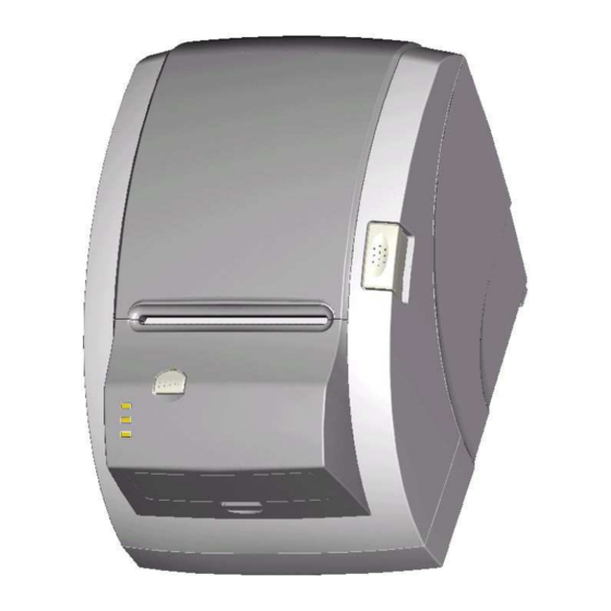
- Page 1 ODP 200 Thermal Receipt Printer Technical Manual...
-
Page 2: Table Of Contents
ODP 200 Technical Manual TABLE OF CONTENTS 1. General Specifications Printing Specifications Character Specifications Auto Cutter Paper Roll Supply Device Paper Specification Printable Area Printing and Cutting Positions Internal Buffer Electrical Characteristics 1.10 EMI and Safety Standards Applied 1.11 Reliability 1.12 Environmental Conditions... -
Page 3: General Specifications
ODP 200 Technical Manual 1. General Specifications 1.1 Printing Specifications 1) Printing method: Thermal line printing 2) Dot density: 180dpi x 180dpi 203dpi x 180dpi 3) Printing direction: Unidirectional with friction feed 4) Printing width: 72mm(2.83"), 576 dot positions (203dpi) 72.2mm(2.84"), 512 dot positions (180dpi) -
Page 4: Character Specifications
ODP 200 Technical Manual 1.2 Character Specifications 1) Number of characters: Alphanumeric characters: Extended graphics: 128 × 11 pages (including one space page) International characters: ① English ② Hangul ③ Chinese (GB2312,Big5) ④ Kanji 2) Character structure: Font A: 12 ℃ 24 Font B: 9 ℃... -
Page 5: Paper Roll Supply Device
ODP 200 Technical Manual 1.4 Paper Roll Supply Device 1) Supply method: Drop-in paper roll 2) Near-end sensor: a) Detection method: Photo Reflector b) Paper roll spool diameter: Inside: 12mm(.47″) Outside: 18mm(.71″) c) Near-end adjustment: Adjusting LEVER d) Remaining amount: Fixed position #1 (approximately 20mm(0.78″) #2... -
Page 6: Printable Area
ODP 200 Technical Manual Printable Area <EPSON Emulation> <82.5mm { 3.25"} paper width model> 82± 0.5mm 0.141mm 512 dots 6.8mm 72.2mm(dot # 1- # 512) <80 mm { 3.15"} paper width model> 79.5± 0.5mm 0.141mm 512 dots 4.3mm 72.2mm(dot # 1- # 512) - Page 7 ODP 200 Technical Manual <60mm { 2.36"} paper width model> 59.5± 0.5mm 0.141mm 384 dots 2.4mm 54.1mm(dot # 1- # 384) <58mm { 2.28"} paper width model> 57.5± 0.5mm 0.141mm 360 dots 3.7mm 50.8mm(dot # 1- # 360) Figure 1.6.1...
- Page 8 ODP 200 Technical Manual <STAR Emulation default setting> <58mm { 2.28"} paper width model> 57.5± 0.5mm 0.125mm 420 dots 2.35mm 2.65mm 52.5mm(dot # 1- # 420) Figure 1.6.2 Printable Area for STAR Emulation (for Default Setting) <80mm { 3.15"} paper width model>...
- Page 9 ODP 200 Technical Manual <60mm { 2.36"} paper width model> 59.5± 0.5mm 0.125mm 420 dots 2.35mm 2.65mm 54.5mm(dot # 1- # 436) Figure 1.6.3 Printable Area for STAR Emulation (When the Paper Width Is Changed) NOTE : The numeric values used here are center values to be used in designing. The printable area may be out of...
-
Page 10: Printing And Cutting Positions
ODP 200 Technical Manual 1.7 Printing and Cutting Positions Appro * 30.5 Appro*21 Manual- cutter position Appro*11.6 Appro * 12.6 Auto- cutter blade position Center of the print dotline Paper feed direction [ Units: mm(Al the numeric values are typical.)] Figure 1.7.1... -
Page 11: Internal Buffer
ODP 200 Technical Manual 1.8 Internal Buffer 1) Receive buffer: 4kbyte 1.9 Electrical Characteristics 1) Supply voltage: +24 VDC ± 7% 2) Current consumption (at 24V): Operating: Approx. 1.5A(at ASCII Printing) Peak:Approx. 10A(at print duty 100%, For 10 seconds or less) Stand-by: Approx. -
Page 12: Configuration
ODP 200 Technical Manual 2. Configuration 2.1 Interface 2.1.1 RS-232 serial interface 2.1.2 Specifications Data transmission: Serial Synchronization: Asynchronous Handshaking: DTR/DSR or XON/XOFF control Signal levels: MARK= -3 to –15V: Logic “1” SPACE= +3 to +15V: Logic “0” Baud rage:... -
Page 13: Serial Interface Connection Example
ODP 200 Technical Manual 2.1.5 Serial interface connection example Host side Printer side TXD ………………………………… RXD DSR ………………………………… DTR RXD ………………………………… TXD DTR ………………………………… DSR FG ………………………………… FG SG ………………………………… SG DETAILS: ◦Set the handshaking so that the transmit data can be received. -
Page 14: Centronics Parallel Interface
ODP 200 Technical Manual SIGNAL GROUND < Figure 2.3 Serial Interface Cable connection > 2.1.6 Centronics parallel interface SIGNAL DESCRIPTION STROBE- Input Synchronize signal Data received DATA0-7 Input Data bit Transmitted 0-7 ACK- Output Data receiving competed BUSY Output Impossible to printer data receiving... - Page 15 ODP 200 Technical Manual tSetup tSTB Busy Peripheral Busy tReady tBUSY nAck tReply tACK tnBUSY tNext...
- Page 16 ODP 200 Technical Manual <Centronics Parallel Interface Cable Connection>...
-
Page 17: Data Receiving Timing(Compatibility Mode)
ODP 200 Technical Manual 2.1.7 Data Receiving Timing (Compatibility Mode) Specifications Characteristics Symbol Min [ns] Max [ns] Data Hold Time (host) tHold Data Setup Time tSetup STROBE Pulse Width tSTB READY Cycle Idle Time tReady BUSY Output Delay Time tBUSY ∝... -
Page 18: Interface Connector
ODP 200 Technical Manual 2.1.9 Interface Connector <D-SUB 25 Female Serial Port> <Centronics Parallel Port> <USB “B” Type Port> <Ethernet Port> <USB COMBO> <Wireless Lan>... -
Page 19: Connectors
ODP 200 Technical Manual 3. Connectors 3.1 Interface Connectors Refer to Section 2.1, Interface 3.2 Electrical Characteristics 1) Input Voltage: DC 24V ± 10% 2) Current Consumption: Operating: Approx. 1.5 A (at ASC℃ printing) Peak: Approx. 10 A (at print duty 100%, For 10 seconds or less) Stand-by: Approx. - Page 20 ODP 200 Technical Manual 3) Drawer kick-out drive signal Output signal: Output voltage: Approximately 24V Output current: 1A or less CAUTION: To avoid an overcurrent, the resistance of the drawer kick-out solenoid must be 24 or more. Output waveform: Outputs the waveforms in Figure 3.2 to the points A and B in Figure 3.3...
-
Page 21: Commands
ODP 200 Technical Manual 4. Commands Command Function Horizontal tab Print and line feed Print and carriage return Print and return to standard mode(in page mode) Cancel print data in page mode DLE EOT Real-time status transmission DLE ENQ Real-time request to printer... - Page 22 ODP 200 Technical Manual Command Function GS L Set left margin GS P Set horizontal and vertical motion units GS V Select cut mode and cut paper GS W Set printing area width GS \ Set relative vertical print position in page mode...
-
Page 23: Command Notation
ODP 200 Technical Manual 4.1. Command Notation [Name] The name of the command. [Format] The code sequence. [Range] Gives the allowable ranges for the arguments. [Description] Describes the command’s functions. [Details] Describes the usage of the command in detail. [Notes] Provides important information on setting and using the printer command, if necessary. -
Page 24: Control Commands
ODP 200 Technical Manual 4.2. Control Commands [Name] Horizontal tab [Format] ASCII Decimal [Description] Moves the print position to the next tab position. [Details] This command is ignored unless the next tab position has been set. If the next horizontal tab position exceeds the printing area, the printer sets the printing position to [Printing area width + 1]. - Page 25 ODP 200 Technical Manual [Name] Print and return to standard mode (in page mode) [Format] ASCII Decimal [Description] Prints the data in the print buffer and returns to standard mode. [Details] The buffer data is deleted after being printed. The printing area set by ESC W is reset to the default setting.
- Page 26 ODP 200 Technical Manual The printer transmits the status without confirming whether the host computer can receive data. The printer executes this command upon receiving it. This command is executed even when the printer is offline, the receive buffer is full, or there is an error status.
- Page 27 ODP 200 Technical Manual n= 3: Error status Off/On Decimal Function Not used. Fixed to Off Not used. Fixed to On Undefined No auto-cutter error Auto-cutter error occurs Not used. Fixed to On No unrecoverable error Unrecoverable error occurs No auto-recoverable error Auto recoverable error occurs Not used.
- Page 28 ODP 200 Technical Manual DLE ENQ n [Name] Real-time request to printer [Format] ASCII Decimal [Range] 1≤n≤2 [Description] Responds to a request from the host computer. n specifies the requests as follows: Request Recover from an error and restart printing from the line where the error occurred...
- Page 29 ODP 200 Technical Manual The printer executes this command upon receiving it. This command is executed even when the printer is off-line, the receive buffer is full, or there is an error status. If print data includes the same character strings as this command, the printer performs the same operation specified by this command.
- Page 30 ODP 200 Technical Manual In page mode, the horizontal or vertical motion unit differs in page mode, depending on starting position of the printable area as follows: ℃When the starting position is set to the upper left or lower right of the printable area using ESC T, the horizontal motion unit (x) is used.
- Page 31 ODP 200 Technical Manual Emphasized mode is effective for alphanumeric and Kanji. All print modes except emphasized mode is effective only for alphanumeric. [Default] n = 0 [Reference] ESC E, ESC -, GS ! ESC $ n [Name] Set absolute print position...
- Page 32 ODP 200 Technical Manual ESC % n [Name] Select/cancel user-defined character set [Format] ASCII Decimal [Range] 0≤n ≤255 [Description] Selects or cancels the user-defined character set When the LSB of n is 0, the user-defined character set is canceled. When the LSB of n is 1, the user-defined character set is selected.
- Page 33 ODP 200 Technical Manual ℃ FS q is executed. ℃ GS * is executed. ℃ The printer is reset or the power is turned off. When the user-defined characters are defined in font B (9 x 24), only the most significant bit of...
- Page 34 ODP 200 Technical Manual...
- Page 35 ODP 200 Technical Manual ESC * * * * m n [d1...dk] [Name] Select bit-image mode * [Format] ASCII d1...dk d1...dk Decimal d1...dk [Range] m = 0, 1, 32, 33 0≤n ≤255 0≤n ≤3 0≤d ≤255 [Description] Selects a bit-image mode using m for the number of dots specified by nL and nH, as follows:...
- Page 36 ODP 200 Technical Manual ESC - n [Name] Turn underline mode on/off [Format] ASCII Decimal [Range] 0≤n ≤2, 48≤n ≤50 [Description] Turns underline mode on or off, based on the following values of n. Function 0, 48 Turns off underline mode...
- Page 37 ODP 200 Technical Manual ESC 3 n [Name] Set line spacing [Format] ASCII Decimal [Range] 0≤n ≤255 [Description] Sets the line spacing to [n x (vertical or horizontal motion unit)] inches. [Details] The line spacing can be set independently in standard mode and in page mode.
- Page 38 ODP 200 Technical Manual ESC ? n [Name] Cancel user-defined characters [Format] ASCII Decimal [Range] 32 ≤n ≤126 [Description] Cancels user-defined characters. [Details] This command cancels the pattern defined for the character code specified by n. After the user-defined characters is canceled, the corresponding pattern for the internal character is printed.
- Page 39 ODP 200 Technical Manual ESC D [n1...nk] NUL [Name] Set horizontal tab positions [Format] ASCII n1……nk n1……nk Decimal n1……nk [Range] 1≤n ≤255 0≤k ≤32 [Description] Set is horizontal tab positions. n specifies the column number for setting a horizontal tab position from the beginning of the line.
- Page 40 ODP 200 Technical Manual ESC E n [Name] Turn emphasized mode on/off [Format] ASCII Decimal [Range] 0≤n ≤255 [Description] Turns emphasized mode on or off. When the LSB of n is 0, emphasized mode is turned off. When the LSB of n is 1, emphasized mode is turned on.
- Page 41 ODP 200 Technical Manual ESC J n [Name] Print and feed paper using minimum units [Format] ASCII Decimal [Range] 0≤n ≤255 [Description] Prints the data in the print buffer and feeds the paper [n x vertical or horizontal motion unit].
- Page 42 ODP 200 Technical Manual ESC L [Name] Select page mode [Format] ASCII Decimal [Description] Switches from standard mode to page mode. [Details] This command is enabled only when input at the beginning of a line in standard mode. This command has no effect in page mode.
- Page 43 ODP 200 Technical Manual ESC M n [Name] Select character font [Format] ASCII Decimal [Range] n= 0, 1 , 48, 49 [Description] Selects character fonts Function 0, 48 Character font A (12 X 24 ) Selected 1, 49 Character font B (9 X 24 ) Selected [Details] The ESC ! command can also select the character fonts.
- Page 44 ODP 200 Technical Manual ESC S [Name] Select standard mode [Format] ASCII Decimal [Description] Switches from page mode to standard mode. [Details] This command is effective only in page mode. Data buffered in page mode and the printable area developed in page mode are cleared.
- Page 45 ODP 200 Technical Manual ESC T n [Name] Select print direction in page mode [Format] ASCII Decimal [Range] 0≤n ≤3, 48≤n ≤51 [Description] Select the print direction and starting position in page mode. n specifies the print direction and starting position as follows:...
- Page 46 ODP 200 Technical Manual ESC V n [Name] Turn 90° clockwise rotation mode on/off [Format] ASCII Decimal [Range] 0≤n ≤1,48≤n ≤49 [Description] Turns 90° clockwise rotation mode on or off. n is used as follows: Function 0, 48 Turns off 90˚ clockwise rotation mode 1, 49 Turns on 90˚...
- Page 47 ODP 200 Technical Manual ESC W xL xH yL yH dxL dxH dyL dyH [Name] Set printing area in page mode [Format] ASCII xL xH yL yH dxL dxH dyL dyH xL xH yL yH dxL dxH dyL dyH Decimal...
- Page 48 ODP 200 Technical Manual This printable area for this printer is approximately 72.2 mm {512/180”} in the horizontal direction and approximately 117.3 mm {1662/360”} in the vertical direction. [Default] xL = xH = yL = yH = 0 dxL = 0, dxH = 2, dyL =126, dyH = 6...
- Page 49 ODP 200 Technical Manual [Reference] ESC $, GS P ESC a n [Name] Select justification [Format] ASCII Decimal [Range] 0≤n ≤2,48 ≤n ≤50 [Description] Aligns all the data in one line to the specified position n selects the justification as follows:...
- Page 50 ODP 200 Technical Manual ESC c 3 n [Name] Select paper sensor(s) to output paper-end signals [Format] ASCII Decimal [Range] 0≤n ≤255 [Description] Selects the paper sensor(s) to output paper end signals. Each bit of n is used as follows:...
- Page 51 ODP 200 Technical Manual ESC c 4 n [Name] Select paper sensor(s) to stop printing [Format] ASCII Decimal [Range] 0≤n ≤255 [Description] Selects the paper sensor(s) used to stop printing when a paper-end is detected, using n as follows. Off / On...
- Page 52 ODP 200 Technical Manual [Description] Enables or disables the panel buttons. When the LSB of n is 0, the panel buttons are enabled. When the LSB of n is 1, the panel buttons are disabled. [Details] Only the lowest bit of n is valid.
- Page 53 ODP 200 Technical Manual ESC t n [Name] Select character code table [Format] ASCII Decimal [Range] 0≤n≤5, 16≤n≤19, n = 255 [Description] Selects a page n from the character code table. Page PC437 [U.S.A., Standard Europe] Katakana PC850 [Multilingual] PC860 [Portuguese]...
- Page 54 ODP 200 Technical Manual CP1257 Baltic CP1123 UKRAINE CP1112 LI THUANIAN CP858 Multilingual Latin I + Euro ISO88597 Greek ISO88592 Latin-2 ESC { n [Name] Turn upside-down printing mode on/off [Format] ASCII Decimal 27 0 ≤ n ≤ 255 [Range] [Description] Turns upside-down printing mode on or off.
- Page 55 ODP 200 Technical Manual FS p n m [Name] Print NV bit image [Format] ASCII Decimal 1 ≤ n ≤ 255 [Range] 0 ≤ m ≤ 3, 48 ≤ m ≤ 51 [Description] Prints a NV bit image n using the mode specified by m.
- Page 56 ODP 200 Technical Manual in quadruple mode (m=3,51). ℃The printing area width is extended to the right in NV bit image mode ℃If the printing area width cannot be extended by one line vertically, the left margin is reduced to accommodate one line vertically.
- Page 57 ODP 200 Technical Manual Therefore it is prohibited to transmit the data including the real-time commands during the execution of this command. NV bit image means a bit image which is defined in a non-volatile memory by FS q and printed by FS p.
- Page 58 ODP 200 Technical Manual Printing of the NV bit image is performed by the FS q command. [Notes] Frequent write command execution may cause damage the NV memory. Therefore, it is recommended to write the NV memory 10 times or less a day.
- Page 59 ODP 200 Technical Manual Character height selection. See Table 2. Character width selection. See Table 1. Table 1. Character Width Selection. Table 2. Character Height Selection. Decimal Width Decimal Width (normal) (normal) (double-width) 2 (double-height) [Details] This command is effective for all characters (except for HRI characters).
- Page 60 ODP 200 Technical Manual This command sets the absolute print position to [ (nL + nH ×256) × (vertical or horizontal motion unit)] inches. If the [ (nL + nH × 256) × (vertical or horizontal motion unit)] exceeds the specified printing area, this command is ignored.
- Page 61 ODP 200 Technical Manual GS \ \ \ \ [Reference] GS / m [Name] Print downloaded bit image [Format] ASCII Decimal 0 ≤ m ≤ 3,48 ≤ m ≤ 51 [Range] [Description] Prints a downloaded bit image using the mode specified by m.
- Page 62 ODP 200 Technical Manual GS ∗ ∗ ∗ ∗ [Reference] GS B n [Name] Turn white/black reverse printing mode on/off [Format] ASCII Decimal 0 ≤ n ≤ 255 [Range] [Description] Turns on or off white/black reverse printing mode. When the LSB of n is 0, white/black reverse printing mode is turned off.
- Page 63 ODP 200 Technical Manual [Format] ASCII Decimal 0 ≤ n ≤ 3, 48 ≤ n ≤ 51 [Range] [Description] Selects the printing position of HRI characters when printing a bar code. n selects the printing position as follows: Printing position...
- Page 64 ODP 200 Technical Manual Not used. Fixed to Off. Not used. Fixed to Off. Undefined. Underfined. Not used. Fixed to Off. [Details] When DTR/DSR control is selected in the serial interface model, the printer transmits the printer ID after confirming that the host is ready to receive data(DSR signal is SPACE).
- Page 65 ODP 200 Technical Manual Left margin Printing width [Details] This command is effective only of the beginning of a line. If this command is input in page made, the printer performs only internal flag operations. This command does not affect printing in page made.
- Page 66 ODP 200 Technical Manual [Default] x = 180, y = 360 ESC SP, ESC $, ESC 3, ESC J, ESC W, ESC \ \ \ \ , GS $, GS L, GS V, GS W, GS \ \ \ \...
- Page 67 ODP 200 Technical Manual The paper feed amount is calculated using the vertical motion unit ( However, the value cannot be less than the minimum horizontal movement amount, and it must be in even units of the minimum horizontal movement amount.
- Page 68 ODP 200 Technical Manual ① The printing area width is extended to the right to accommodate one character. Printable area Left margin Extended to right Printing area width set by ② f the printing area width cannot be extended sufficiently, the left margin is reduced to...
- Page 69 ODP 200 Technical Manual [Name] Set relative vertical print position in page mode \ [Format] ASCII Decimal 29 0 ≤ nL ≤ 255 [Range] 0 ≤ nH ≤ 255 [Description] Sets the relative vertical print starting position from the current position in page mode.
- Page 70 ODP 200 Technical Manual Drawer kick-out connector pin 3 status enabled. On-line/off-line status disabled. On-line/off-line status enabled Error status disabled Error status enabled. Paper roll sensor status disabled. Paper roll sensor status enabled. 4–7 Undefined. [Details] If any of the status items in the table above are enabled, the printer transmits the status when this command is executed.
- Page 71 ODP 200 Technical Manual correcting the cause of the error and executing DLE ENQ n (1 ≤ n ≤ 2). If an error due to a circuit failure (e.g. wire break) occurs, it is impossible to recover. Bit 6: When printing is stopped due to high print head temperature until the print head temperature drops sufficiently or when the paper roll cover is open during printing, bit 6 is On.
- Page 72 ODP 200 Technical Manual GS h n [Name] Select barcode height [Format] ASCII Decimal 1 ≤ n ≤ 255 [Range] [Description] Select the height of the bar code. n specifies the number of dots in the vertical direction. [Default] n = 162...
- Page 73 ODP 200 Technical Manual 7 ≤ n ≤ 8 48 ≤ d ≤ 57 EAN8 1 ≤ n ≤ 255 48 ≤ d ≤ 57, 65 ≤ d ≤ 90, CODE39 32,36,37,43,45,46,47 ℃ 1 ≤ n ≤ 255 48 ≤ d ≤ 57 (even number) 1 ≤...
- Page 74 ODP 200 Technical Manual ASC℃ Decimal ASC℃ Decimal ■U ■P ■A ■Q ■B ■R ■C ■S ■D ■T ■E ■U ■F ■V ■G ■W ■H ■X ■I ■Y ■J ■Z ■K ■A ■L ■B ■M ■C ■N ■D ■0 ■E ■T...
- Page 75 ODP 200 Technical Manual “{“ 7B,7B 123,123 [Example] Example data for printing “No. 123456” In this example, the printer first prints “No.” using CODE B, then prints the following numbers using CODE C. GS k 73 10 123 66 78 111 46 123 67 12 34 56 If the top of the bar code data is not the code set selection character, the printer stops command processing and processes the following data as normal data.
- Page 76 ODP 200 Technical Manual Paper sensor status ( n = 1, 49): Off / On Decimal Status for ASB Paper roll near-end sensor: paper adequate. Paper roll near-end sensor: paper near end. Paper roll end sensor: paper adequate. (0C) (12) Paper roll end sensor: paper near end.
- Page 77 ODP 200 Technical Manual yL, yH, select the number of data bytes (xL+xH×256) in the vertical direction for the bit image. [Details] In standard mode, this command is effective only when there is no data in the print buffer. This command has no effect in all print modes (character size, emphasized, double-strike, upside-down, underline, white/black reverse printing, etc.) for raster bit image.
- Page 78 ODP 200 Technical Manual ESC i [Name] Full cut. [Format] ASCII Decimal [Description] When this command is received, paper is cut (only when the auto cutter is loaded). ESC m [Name] Partial cut. [Format] ASCII Decimal [Description] When this command is received, paper is cut (only when the auto cutter is loaded).
- Page 79 ODP 200 Technical Manual Decimal 0 ≤ n ≤ 255 [Range] [Description] Sets the print mode for Kanji characters, using n as follows: Off/On Decimal Function Undefined. Undefined. Double-width mode is OFF. Double-width mode is ON. Double-height mode is OFF.
- Page 80 ODP 200 Technical Manual not, then processed the first byte and the second byte if the code is for Kanji. Kanji codes are processed in the order of the first byte and second byte. Kanji character mode is not selected when the power is turned on.
- Page 81 ODP 200 Technical Manual For Simplified Chinese/Traditional Chinese/Korean model: When the Kanji character mode is not selected, all character codes are processed one byte at a time as ASCII code. Kanji character mode is selected when the power is turned on.
- Page 82 ODP 200 Technical Manual [Reference] FS C FS C n [Name] Select Kanji character code system [Format] ASCII Decimal [Range] n = 0, 1, 48, 49 [Description] Selects a Kanji character code system, based on the following values of n:...
- Page 83 ODP 200 Technical Manual Decimal 0 ≤ n1 ≤ 255 [Range] 0 ≤ n2 ≤ 255 [Description] Sets left- and right-side Kanji character spacing n1 and n2, respectively. When the printer model used supports GS P, the left-side character spacing is [n1 x horizontal or vertical motion units], and the right-side character spacing is [n2 x horizontal or vertical motion units].
- Page 84 ODP 200 Technical Manual FS ! or GS ! can also select and cancel quadruple-size mode by selecting double-height and double-width modes, and the setting of the last received command is effective. [Default] n = 0 [Reference] FS !, GS !
Need help?
Do you have a question about the ODP 200 and is the answer not in the manual?
Questions and answers