
Subscribe to Our Youtube Channel
Related Manuals for Avery Weigh-Tronix XR 2000


Summary of Contents for Avery Weigh-Tronix XR 2000
-
Page 1: Installation Instructions
XR Series LED Remote Displays Installation Instructions NORTH AMERICA AWT35-500303 Issue AD... - Page 2 Full acknowledgment of the source must be given. Avery Weigh-Tronix is a registered trade mark of the Avery Weigh-Tronix, LLC. This publication was correct at the time of going to print however, Avery Weigh-Tronix, LLC reserves the right to alter without notice the specification, design, price or conditions of supply of any product or service at any time.
-
Page 3: Table Of Contents
Lowering the Electronics Plate .................. 12 Mounting Instructions ....................12 Installing the XR 2000 ...................... 15 Opening the XR 2000 Enclosure ................15 Mounting Instructions ....................15 Chapter 4 Wiring ............................17 Wiring the XR 4500, 4500TL or 6500 ................17 Power Wiring ...................... - Page 4 Chapter 8 XR 4500 TL Traffic Light Control ..................41 Built-in Traffic Light (XR 4500TL Only) ................41 Chapter 9 Time and Date (not available on XR 2000) ................42 Set Time & Date ....................... 42 Adjust Time ....................... 42 Adjust Date ........................
-
Page 5: Chapter 1 General Information And Warnings
About this manual General information and warnings 1.1 About this manual This manual is divided into chapters by the chapter number and the large text at the top of a page. Subsections are labeled as shown by the 1 and 1.1 headings shown above. The names of the chapter and the next subsection level appear at the top of alternating pages of the manual to remind you of where you are in the manual. -
Page 6: Installation
1 General information and warnings 1.2 Installation DANGER: RISK OF ELECTRICAL SHOCK. NO USER SERVICEABLE PARTS. REFER TO QUALIFIED SERVICE PERSONNEL FOR SERVICE. 1.3 Electrical installation CAUTION: The power cable must be connected to an earth-grounded electrical outlet. The electrical supply must have a circuit breaker with an appropriate rating to protect from over-current conditions. -
Page 7: Routine Maintenance
Routine maintenance 1.4 Routine maintenance IMPORTANT: This equipment must be routinely checked for proper operation and calibration. Application and usage will determine the frequency of calibration required for safe operation. Always turn off the machine and isolate from the power supply before starting any routine maintenance to avoid the possibility of electric shock. -
Page 8: Fcc And Emc Declarations Of Compliance
1 General information and warnings 1.7 FCC and EMC declarations of compliance United States This equipment has been tested and found to comply with the limits for a Class A digital device, pursuant to Part 15 of the FCC Rules. These limits are designed to provide reasonable protection against harmful interference when the equipment is operated in a commercial environment. -
Page 9: Chapter 2 Introduction
Like all Avery Weigh-Tronix products, the XR remote displays are designed with durability, functionality and versatility in mind. If you should need technical assistance, please contact your local, authorized Avery Weigh-Tronix distributor. -
Page 10: Keypad
NT = Net Weighing Mode lb = Pounds kg = Kilograms 2.2 Keypad All models of the XR, except the XR 2000, have a keypad on the bottom of the unit. See illustration of the keypad in Figure 2.2. Figure 2.2 Keypad The keypad has three pushbuttons or keys and a light sensor window. -
Page 11: Chapter 3 Installation
Installing the XR 4500, XR 4500TL or XR 6500 Installation 3.1 Installing the XR 4500, XR 4500TL or XR 6500 3.1.1 Pre-installation (Receiving Inspection) It is always good practice to verify that the unit is complete and undamaged upon receipt. Check over packaging for any signs of damage. -
Page 12: Lowering The Electronics Plate
3 Installation 3.1.3 Lowering the Electronics Plate Remove the three (3) captive screws holding the electronics plate to the main enclosure. See Figure 3.2. Captive Screws Figure 3.2 Open enclosure Slowly, allow the electronics plate to swing down. The controller board and power supply board are now accessible for installation, wiring and service. - Page 13 Installing the XR 4500, XR 4500TL or XR 6500 Run power and communication cables into the enclosure via strain reliefs (as required). The electronics carriage may be removed to reduce weight when installing. Mounting hole size in the case is 3/8”. Wall Mounting Hole patterns for the XR series are given in Figure 3.4...
- Page 14 3 Installation Fasten the XR display to the pole mounting bracket as outlined in the mounting instructions (See Figure 3.6). The pole mounting bracket allows use of poles or beams up to eight inches in diameter. Figure 3.6 Pole mounting bracket Visor Option Loosen the mounting hardware on the main enclosure 1/8th inch.
-
Page 15: Installing The Xr 2000
Guide the front panel away from the main enclosure. Be sure to watch the internal cable connections! See Figure 3.8 Figure 3.8 XR 2000 enclosure laid open 3.2.2 Mounting Instructions Mounting hole size in the case is 5/16”. Inspect the installation site for properly grounded power. - Page 16 3 Installation Figure 3.9 XR 2000 dimensions XR Series Installation Instructions...
-
Page 17: Chapter 4 Wiring
Wiring the XR 4500, 4500TL or 6500 Wiring 4.1 Wiring the XR 4500, 4500TL or 6500 4.1.1 Power Wiring XR displays are wired for power at the factory. The factory supplied power cable can be removed for direct AC wiring if necessary. 4.1.2 Communications Wiring All communications wiring terminates at the controller board. - Page 18 4 Wiring RS 232 Daisy Chain / Multi-Drop Wiring INDICATOR TO RD 1 TO RD 2 No connection for Daisy Chain. RX for Multi-drop. RS 422/485 Wiring Terminate the indicator’s communication wires at the RS 485 terminal (J4), shown in Figure 4.1.
- Page 19 Wiring the XR 4500, 4500TL or 6500 RS 485 Daisy Chain / Multi-Drop Wiring Terminate the indicator’s communication wires at the RS 485 terminal (J4), shown in Figure 4.1, using one of the following methods: Parallel Multi-drop wiring SCALE CONTROLLER TO RD 1 TO RD 2 TO RD 3...
- Page 20 4 Wiring 20mA Current Loop Wiring Terminate the indicator’s communication wires at the 20mA Current Loop terminal (J5), shown in Figure 4.1. See table below for pin assignments: INDICATOR TO XR 20 mA TX + RECEIVE POSITIVE (RX +) 20 mA TX - RECEIVE NEGATIVE (RX -) 20mA Current Loop Mode Switch After the current loop is wired, ACTIVE or PASSIVE mode must be selected...
-
Page 21: Wiring The Xr 2000
Wiring the XR 2000 4.2 Wiring the XR 2000 4.2.1 Power Wiring XR displays are wired for power at the factory. The factory supplied power cable can be removed for direct AC wiring if necessary. 4.2.2 Communication Wiring All communications wiring terminates at the controller board. Communications should be wired before applying power to the unit. - Page 22 4 Wiring Terminate the indicator’s communication wires at the RS 232 terminal (J3). See table below: INDICATOR TO XR TRANSMIT (TX) RECEIVE (RX) RECEIVE (RX) NO CONNECTION SIGNAL GROUND (GND) SIGNAL GROUND (SIG GND) RS 422 Wiring Set the Communication Input Jumper (JP 1) to RS422 / 485. Terminate the indicator’s communication wires at the RS 422 / 485 terminal (J4).
- Page 23 Wiring the XR 2000 RS 485 Multi-Drop Wiring Set the Communication Input Jumper (JP 1) to RS422 / 485. Parallel Multi-drop wiring SCALE CONTROLLER TO RD 1 TO RD 2 TO RD 3 ETC. TX A RX A RX A...
-
Page 24: Chapter 5 Wireless Communication
Install the radio module. Plug the module into terminals on the main PC board. Figure 5.1. The radio module plugs into the XR 2000 controller board in similar fashion. Route the radio signal cable to the bottom of the electronics carriage and secure the SMA terminal through the available hole. -
Page 25: Base Station Wireless Transceiver
Wireless Set-up for All XR Models 5.1.3 Base Station Wireless Transceiver The ScaleLink wireless transceiver is shown in Figure 5.2. Refer to the installation manual that is included with the ScaleLink for connection and configuration information. Figure 5.2 Base station (connects to the indicator) Figure 5.3 shows the inside of the ScaleLink. -
Page 26: Wireless Connection Test
5 Wireless Communication 5.2 Wireless Connection Test Verify that both the base station wireless transceiver and the XR are set to the same radio channel. If the XR’s readings are incorrect, erratic, or very slow, a different radio channel may need to be selected. -
Page 27: Chapter 6 Start-Up
6.2 Reset Button The RESET button (marked as RST on the XR 2000) on the controller board allows the technician to cycle power on the unit without disconnecting/connecting AC power. See Figure 6.1. -
Page 28: Learn Button
Learn Parameters on page If Automatic Start-up Auto-Learn is disabled, the LEARN button (marked as LRN on the XR 2000) on the Controller board must be pressed to enter Auto-Learn mode. 6.5 Diagnostic Indicator Lights The XR has seven diagnostic indicator lights located on the controller board. See the... - Page 29 Diagnostic Indicator Lights Figure 6.3 Lights and switches on the XR 2000 controller board 3.3V Light Turns on when voltage is supplied to the controller board. 12V Light Turns on when voltage is supplied to the display boards. STATUS Light The STATUS light blinks when power is applied to the unit.
-
Page 30: Chapter 7 Configuration Mode
7 Configuration Mode Configuration Mode To set the different parameters available in the XR series, you must enter a configuration mode and then set each parameter to your desired value. Follow the steps below to enter the configuration mode and to set the parameters. 7.1 Entering Configuration Mode On the keypad on the bottom of the display press the UP and DOWN arrow keys together. -
Page 31: Configuration Parameters
Configuration Parameters 7.2 Configuration Parameters Use the instructions in ’Entering Configuration Mode’, section 7.1 to access and change the following parameters. 7.2.1 Parameter 1.0: Daytime Brightness Level Value Description 0 = Low Set the brightness of the display for daytime viewing. The built-in light sensor 1 = Med Low automatically detects daylight conditions and sets the display brightness to this level. -
Page 32: Parameter 1.4: Multi-Drop Id
7 Configuration Mode 7.2.5 Parameter 1.4: Multi-Drop ID Value Description 0 = ID 0< Sets the unit ID if multiple remote displays are networked together. Up to four XR 1 = ID 1 displays can be networked on a single serial or radio connection. Messages are sent 2 = ID 2 to individual displays using control codes and these IDs. -
Page 33: Auto-Learn Parameters
Auto-Learn Parameters 7.3 Auto-Learn Parameters 7.3.1 Parameter 2.0: Manual Learn (Assisted Learn) Value Description Lxxxxx Manual Learn activates Auto-Learn Mode from inside Configuration Mode. The remote display will analyze and attempt to learn the string. The message LEARN is displayed. When the remote display is successful, the weight will be shown on the display. -
Page 34: Parameter 2.3: Set Scale Over
7 Configuration Mode 7.3.4 Parameter 2.3: Set Scale Over Value Description 0 = Auto< If there is no scale over status character in the weight string, or the Value for scale over target weight indicator continues to transmit past maximum capacity, the unit can be set to blank the display when the weight goes past a preset weight value. -
Page 35: Time / Date / Temp Parameters
Time / Date / Temp Parameters 7.4 Time / Date / Temp Parameters The XR remote display can cycle between displaying weight, time, date and temperature every five seconds when: a) the weight display is at zero AND; b) there is no activity on the scale for the selected time period. -
Page 36: Diagnostic Parameters
7 Configuration Mode 7.5 Diagnostic Parameters 7.5.1 Parameter 9.0: Com Port Value Description 0 = RS232 Displays the currently active Com Port. 1 = RADIO 2 = 20mA 3 = RS485 7.5.2 Parameter 9.1: String Counter Value Description 0 to 65535 Counter indicates the number of characters received. -
Page 37: Parameter 9.8: Test Display
Diagnostic Parameters 7.5.6 Parameter 9.8: Test Display Value Description Cycles through time, digits, annunciators and decimal characters. 7.5.7 Parameter 9.9: Reset Defaults Value Description 0 = Do Not Reset Resets the configuration parameters to factory defaults. 1 = RESET XR Series Installation Instructions... -
Page 38: Config Switches (Xr 2000)
In some cases, the scale indicator may transmit leading zeros in the output string. If leading zeros are NOT required, they may be suppressed. The XR 2000 will automatically remove the leading zeros and replace them with blank spaces on the display. - Page 39 If the wireless connection experiences interference problems from another radio site, switching radio channels will most likely correct the problem. The XR 2000 remote display must be configured with the same radio channel as the wireless transceiver connected to the indicator. See...
- Page 40 Switches 8 & 9: Utility Program Select Please see the XR 2000 Utility Programs on page 49 for program overviews. The XR 2000 has built-in utility programs that run in conjunction with the normal display functions. PROGRAM SW 8 SW 9 1 –...
-
Page 41: Chapter 8 Xr 4500 Tl Traffic Light Control
Built-in Traffic Light (XR 4500TL Only) XR 4500 TL Traffic Light Control 8.1 Built-in Traffic Light (XR 4500TL Only) The built-in traffic light may be controlled by remote switch, serial commands, or the pre-installed utility programs. Remote Switch Wire a dry contact, push to make switch to the Stop Light Remote Switch terminal (J23) on the Controller board. -
Page 42: Chapter 9 Time And Date (Not Available On Xr 2000)
9 Time and Date (not available on XR 2000) Time and Date (not available on XR 2000) The XR remote display has a precision time clock that compensates for variable temperature conditions. The battery on the Controller board (J22) provides back-up power for this clock. -
Page 43: Chapter 10 Temperature Probe Installation (Not On Xr 2000)
10 Temperature Probe Installation (not on XR 2000) Unpack the optional Temperature Probe Assembly. This assembly consists of the weather-sealed temperature probe contained in a Strain-Relief. A 4-conductor cable runs from the temperature probe to a 4 pin connector. Ensure the XR display is disconnected from power and open the enclosure. - Page 44 10 Temperature Probe Installation (not on XR 2000) Figure 10.2 J9 terminal for temperature probe connection The XR’s Digital Temperature Probe ensures accuracy to within ± 1 degree and will never need to be calibrated. XR Series Installation Instructions...
-
Page 45: Chapter 11 Xr Utility Programs
11.1 XR 4500, XR 4500TL, and XR 6500 Utility Programs 11 XR Utility Programs 11.1 XR 4500, XR 4500TL, and XR 6500 Utility Programs The XR remote displays have several auxiliary functions that may be activated via Parameter 1.6 in Configuration Mode. 11.1.1 Program 0: Normal Operation No utility program is selected. -
Page 46: Program 5: Command Mode
11 XR Utility Programs 11.1.6 Program 5: Command Mode All XR displays can be setup to receive commands directly from the scale system or PC. Supported commands include transmitting weights, basic alphanumeric messaging, traffic light control, and additional display functions. Command mode disables Auto-Learn and fixes communications at 9600-N-8-1. - Page 47 11.1 XR 4500, XR 4500TL, and XR 6500 Utility Programs Control Commands Control commands are single ASCII characters (preceded by @ and followed by <CR>) that are transmitted to the XR to control additional features such as the built-in traffic light (XR 4500 TL). CONTROL COMMAND CHARACTER ASCII...
-
Page 48: Program 12: Legacy Command Mode
11 XR Utility Programs Multi-Drop addressing The XRs using Multi-drop networking must be in Command Mode. The Multi-drop ID (0 to 3) must also be set. (See Parameter 1.4: Multi-Drop ID on page 32). When using Multi-drop, the XR will only respond after it has been selected. To select a display, transmit a # character (ASCII 35) followed by the correct ID number and a <CR>... -
Page 49: Xr 2000 Utility Programs
11.2 XR 2000 Utility Programs 11.2 XR 2000 Utility Programs The XR 2000 has several auxiliary functions that may be activated via the CONFIG dip switches on the controller board. PROGRAM SW 8 SW 9 1 – NORMAL Mode (No program) 2 –... - Page 50 11 XR Utility Programs Activating Command Mode To enable command mode, CONFIG dip switches 8 and 9 on the controller board must be set as follows: PROGRAM SW 8 SW 9 4 – COMMAND Mode Switch settings do not take affect until the XR is reset or powered up again. Transmit a Weight String Use numeric ASCII characters followed by a <CR>...
- Page 51 11.2 XR 2000 Utility Programs Send 3 different weights to 3 different scoreboards: “#0 2000LG<CR>#1 3000LG<CR>#2 5000LG<CR>“ Send the text “hello” to scoreboard address 3. “#3 HELLO<CR> XR Series Installation Instructions...
-
Page 52: Chapter 12 Troubleshooting & Error Messages
12 Troubleshooting & Error Messages 12 Troubleshooting & Error Messages Problem Cause and/or Probable Solution Unit won’t power up: • Verify AC power source (Outlets, breakers, etc.) • Check terminal block connections inside the main enclosure. • Verify power wiring from terminal block to the power supply board. - Page 53 RS485 light not flashing: • Verify the RS485 terminal is being used and check communications wiring at the indicator. • Verify that data is being sent to the XR from the indicator and that the data string contains numeric characters. 20mA light not flashing: •...
-
Page 54: Chapter 13 Spare Parts Lists
13 Spare Parts Lists 13 Spare Parts Lists Following are the part numbers for the spare parts needed for the XR series remote displays. Additional Parts for the XR 2000 AWT PN 60339 DESCRIPTION -4016 XR 2000 REMOTE DISPLAY, COMPLETE ASSY. - Page 55 Additional Parts for the XR 4500 DESCRIPTION AWT25-500612 CONTROLLER BOARD 60314-0013 GORTEX BREATHER VENT AWT25-500616 KEYPAD W/LIGHT SENSOR WINDOW 60339-0048 POWER SUPPLY BOARD 60339-0055 10" RIBBON CHT SENSOR WINDOW 60339-0063 20" RIBBON CABLE 60339-0071 9" GROUND WIRE 60339-0089 11" GROUND WIRE 60339-0097 POWER SUPPLY TO CONTROLLER BOARD CABLE 60339-0105...
- Page 56 13 Spare Parts Lists Additional Parts for the XR 4500 TL 60339-3026 DISPLAY DIGIT WITH SIGNAL LIGHT 60339-3034 DISPLAY DIGIT PC BD 60339-2077 VISOR AWT05-503348 POLE MOUNT KIT AWT25-500617 TEMPERATURE OPTION Additional Parts for the XR 6500 DESCRIPTION AWT25-500612 XR CONTROLLER BOARD 60314-0013 GORTEX BREATHER VENT AWT25-500616...
-
Page 57: Chapter 14 Specifications
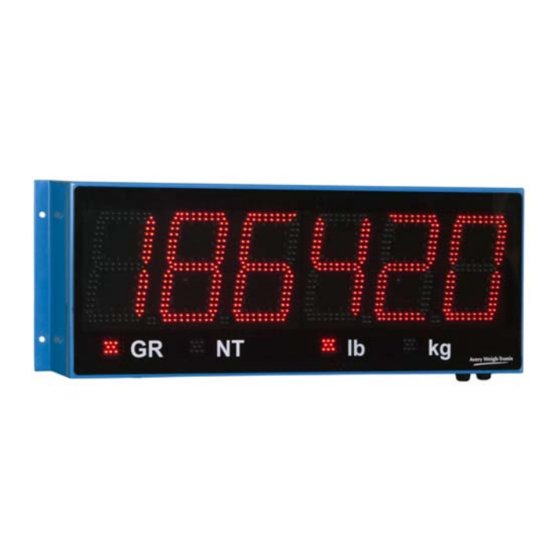
4.5” characters (XR 4500 and XR 4500TL), 275 foot viewing range 6.5” characters (XR 6500), 325 foot viewing range • 1 or 2 decimals (XR 4500, XR 4500TL and XR 6500) up to 5 decimals (XR 2000) • 4 annunciators (GR, NT, lb, KG) •... - Page 58 14 Specifications XR Series Installation Instructions...
- Page 60 Avery Weigh-Tronix USA 1000 Armstrong Dr. Fairmont MN 56031 USA Tel:507-238-4461 Fax:507-238-4195 Email: usinfo@awtxglobal.com www.wtxweb.com Avery Weigh-Tronix UK Foundry Lane, Smethwick, West Midlands, England B66 2LP Tel:+44 (0) 8453 66 77 88 Fax: +44 (0)121 224 8183 Email: info@awtxglobal.com www.averyweigh-tronix.com...
Need help?
Do you have a question about the XR 2000 and is the answer not in the manual?
Questions and answers