
Subscribe to Our Youtube Channel
Related Manuals for Avery Weigh-Tronix XR Series


Summary of Contents for Avery Weigh-Tronix XR Series
- Page 1 XR Series LED Remote Displays XR LED Remote Displays Installation and Technical Instructions ENGLISH AWT35-000043 Issue AC May 21, 2007 *43121-0012*...
- Page 2 XR Series_i_AWT35-000043.book...
- Page 3 The copyright and the foregoing restriction on reproduction and use extend to all media in which the information may be embodied. Avery Weigh-Tronix is a trading name of Weigh-Tronix, Inc Trademarks and acknowledgements Avery Weigh-Tronix, Avery Berkel, Dillon, NCI and Salter Brecknell are registered trademarks in certain jurisdictions.
- Page 4 XR Series Installation and Technical Instructions...
-
Page 5: Table Of Contents
CONFIG and OPTION Switches (XR 4500, 4500TL, and XR 6500)...... 34 CONFIG Switches ..................35 OPTIONS Switches..................37 CONFIG Switches (XR 2000)................. 39 Chapter 7: Traffic Light Control..................41 External Traffic Lights (XR 4500, XR 4500TL and XR 6500) ......... 41 XR Series Installation and Technical Instructions... - Page 6 Program 3: Axle Weighing - Driving On ............44 Program 4: Command Mode................. 45 XR 2000 Utility Programs ..................47 Chapter 9: Troubleshooting & Error Messages ............49 Chapter 10: Spare Parts Lists ..................52 Chapter 11: Specifications................... 56 XR Series Installation and Technical Instructions...
-
Page 7: Chapter 1: Introduction
Introduction Thank you for purchasing an XR series remote display. The XR series incorporate the highest performance standards and the most standard features of any weighing display, making them the best choice for virtually any remote viewing application. Like all Avery Weigh-Tronix products, the XR remote displays are designed with durability, functionality and versatility in mind. -
Page 8: Display
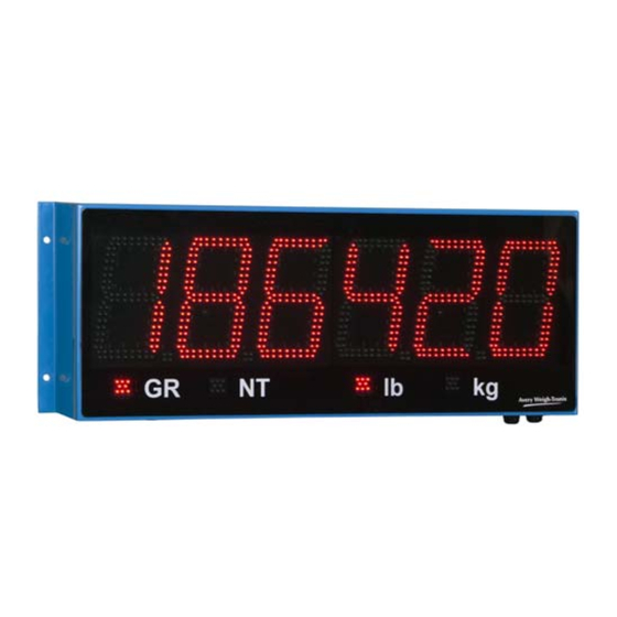
(Five decimals on the XR 2000). The units have four annunciators under the display with bright LED markers: GR = Gross Weighing Mode NT = Net Weighing Mode lb = Pounds kg = Kilograms XR Series Installation and Technical Instructions... -
Page 9: Chapter 2: Installation
Guide the electronics carriage out of the main enclosure, being careful to avoid bending any LED leads. Each LED is mounted very close to the PCB to prevent bending. Place the electronics carriage bottom-down on the flat surface as illustrated. See Figure XR Series Installation and Technical Instructions... -
Page 10: Removing The Electronics Carriage
5/16ths bolts. The electronics carriage may be Run power and communication cables into the enclosure via strain removed to reduce weight when reliefs (as required). installing. Mounting hole size in the case is 3/8”. XR Series Installation and Technical Instructions... - Page 11 Wall Mounting Hole patterns for the XR series are given in Figure 2.2. XR 4500 XR 4500TL and XR 6500 Figure 2.2 Outline dimensions and hole pattern Pole Mounting Bracket Select appropriate height and fasten the small “C” bracket to the pole using the mounting clamps provided.
- Page 12 Installation Figure 2.3 Pole mounting bracket XR Series Installation and Technical Instructions...
-
Page 13: Opening The Enclosure (Mounted)
PCB to prevent bending. The electronics carriage has tabs on either end that allow it to rest on the main enclosure’s flange when mounted (As seen in Figure & 2.6). Figure 2.5 Front view XR Series Installation and Technical Instructions... - Page 14 Remove the two (2) captive screws holding the electronics plate to the electronics carriage. Slowly, allow the electronics plate to swing down, making access easier for wiring and service. See Figure 2.7. Figure 2.7 Side view XR Series Installation and Technical Instructions...
- Page 15 Disconnect the green ground wire from the electronics carriage frame. Angle the electronics carriage so the tabs are at opposite corners of the main enclosure opening. Guide the electronics carriage free of the main enclosure. XR Series Installation and Technical Instructions...
-
Page 16: Installing The Xr 2000
Use proper hardware, including wall anchors where necessary, when mounting the enclosure. Secure the main enclosure to wall or pole mounted bracket with 5/16ths bolts. Run power and communication cables into the enclosure via strain reliefs (as required). XR Series Installation and Technical Instructions... - Page 17 2.2 Installing the XR 2000 Figure 2.9 XR 2000 dimensions XR Series Installation and Technical Instructions...
-
Page 18: Chapter 3: Wiring
AC Power Terminal Block, not directly at the Power Supply board. AC POWER TO TERMINAL BLOCK HOT (+) PIN 3 NEUTRAL (-) PIN 2 GROUND (GND) PIN 1 Replace the terminal block and fasten on mounting posts. XR Series Installation and Technical Instructions... -
Page 19: Communications Wiring
A communications input type (RS 232, RS 422/485, or 20 mA Loop) must be selected by placing the jumper on the appropriate pins. See photo and illustrations in Figure 3.2. Photo shows the input select jumpers circled in a thick white line. Figure 3.2 Jumper positions XR Series Installation and Technical Instructions... - Page 20 See the table below for pin assignments: INDICATOR TO XR TRANSMIT (TX) RECEIVE (RX) RECEIVE (RX) NO CONNECTION SIGNAL GROUND (GND) SIGNAL GROUND (SIG GND) RS 232 Daisy Chain INDICATOR TO RD 1 TO RD 2 XR Series Installation and Technical Instructions...
- Page 21 (J4), shown in Figure 3.4. Figure 3.4 RS 422/485 Terminal See the table below for pin assignments: INDICATOR TO XR TRANSMIT A (TX A) RECEIVE A (RX A) TRANSMIT B (TX B) RECEIVE B (RX B) XR Series Installation and Technical Instructions...
- Page 22 RX A TX B RX B RX B RX B RX B Split Multi-Drop Wiring Multi-Drop IDs are set using the CONFIG Dip-switches. For settings, see Switches 8 & 9: Multi- Drop ID on page XR Series Installation and Technical Instructions...
- Page 23 Select Active mode if the XR is required to supply the current to the communicating device. • Select Passive mode if the communicating device (indicator) supplies the current to the XR. • If unsure of these requirements, check the device’s manual. Figure 3.6 20 mA Mode Switch XR Series Installation and Technical Instructions...
-
Page 24: Wiring The Xr 2000
Ensure that the internal power cable is connected to the power supply board. See Figure 3.7. HIGH VOLTAGE! Only trained personnel should attempt the direct AC wiring procedure. Figure 3.7 XR 2000 power connection XR Series Installation and Technical Instructions... -
Page 25: Communication Wiring
Set the Communication Input Jumper (JP 1) to RS232. Terminate the indicator’s communication wires at the RS 232 terminal (J3). See table below: INDICATOR TO XR TRANSMIT (TX) RECEIVE (RX) RECEIVE (RX) NO CONNECTION SIGNAL GROUND (GND) SIGNAL GROUND (SIG GND) XR Series Installation and Technical Instructions... - Page 26 Terminate the indicator’s communication wires at the 20 mA Current Loop terminal (J5). See table below: INDICATOR TO XR 20 mA TX + RECEIVE POSITIVE (RX +) 20 mA TX - RECEIVE NEGATIVE (RX -) XR Series Installation and Technical Instructions...
- Page 27 Select Active mode if the XR is required to supply the current to the communicating device. • Select Passive mode if the communicating device (indicator) supplies the current to the XR. • If unsure of these requirements, check the device’s manual. XR Series Installation and Technical Instructions...
-
Page 28: Chapter 4: Wireless Communication
Connect the base station to scale indicator (or other appropriate communication settings, as the device) using a serial interface cable. Interface cables are Beldon base station’s settings may need Type 8723. to be adjusted to match. XR Series Installation and Technical Instructions... -
Page 29: Base Station Wireless Transceiver
Figure 4.2 Base station (connects to the indicator) Figure shows the left end of the base station. Figure 4.3 Base station, view 1 Figure shows the opposite end of the base station. Figure 4.4 Base station, view 2 XR Series Installation and Technical Instructions... - Page 30 XStream software package. Refer to the XStream Start- Up Guide for information. Power the base station using the supplied 12VDC power supply. Power up the indicator and base station to transmit radio signals. XR Series Installation and Technical Instructions...
-
Page 31: Wireless Connection Test
Verify that both the base station wireless transceiver and the XR are set to the same radio channel. If the XR’s readings are incorrect, erratic, or very slow, a different radio channel may need to be selected. XR Series Installation and Technical Instructions... -
Page 32: Chapter 5: Start-Up
If Automatic Start-up Auto-Learn is disabled, the LEARN button be disabled for custom (marked as LRN on the XR 2000) on the Controller board must be applications. See Switch 6: Start- pressed to enter Auto-Learn mode. up Auto-Learn on page XR Series Installation and Technical Instructions... -
Page 33: Diagnostic Indicator Lights
The COM light flashes on each time the XR receives a character through any of its COM Ports (including the radio). RADIO Light: The RADIO light flashes on when the XR’s radio module receives data. This light will only illuminate if the radio module is installed. XR Series Installation and Technical Instructions... -
Page 34: Chapter 6: Configuration & Options
XR has been reset (Cycle the controller board (SW 3 & SW 4) to set-up the configuration and options. power directly or press the RESET These are shown in Figure 6.1. button). Figure 6.1 CONFIG and OPTIONS switches XR Series Installation and Technical Instructions... -
Page 35: Config Switches
Switch 5: Mirror Display Mode The XR’s digits may be mirrored for applications where the display is viewed from a vehicle’s rear-view or side-view mirrors. MIRROR DISPLAY MODE SWITCH 5 OFF (Default – Digits normal) ON (Digits mirrored) XR Series Installation and Technical Instructions... - Page 36 Multi-Drop IDs. be set in the OFF position. For Multi-Drop instructions, see Multi-Drop addressing on page MULTI-DROP I.D. SWITCH 8 SWITCH 9 (Default) OFF XR Series Installation and Technical Instructions...
-
Page 37: Options Switches
LEADING ZEROS SWITCH 6 ENABLED (Default) DISABLED (Remove Leading Zeros) Leading zeros may also be disabled using the scale indicator (if possible). XR Series Installation and Technical Instructions... - Page 38 If the wireless connection experiences interference problems from another radio site, switching radio channels will most likely correct the problem. The base station radio connected to the scale indicator must be configured with the same radio channel as the XR. XR Series Installation and Technical Instructions...
-
Page 39: Config Switches (Xr 2000)
In certain situations, it may be necessary to disable this feature. Once disabled, the LEARN button on the controller board must be pressed before the XR will go into Auto-Learn mode. START-UP AUTO-LEARN SWITCH 3 ENABLED (Default) DISABLED XR Series Installation and Technical Instructions... - Page 40 Programs on page 47 for program normal display functions. overviews. PROGRAM SW 8 SW 9 1 – NORMAL Mode (No program) 2 – FREEZE Weight 3 – Reserved for future use 4 – COMMAND mode. XR Series Installation and Technical Instructions...
-
Page 41: Chapter 7: Traffic Light Control
Wire the traffic light to the traffic light terminal (J7) on the Controller board. See Figure 7.1. Figure 7.1 Traffic light terminal See the pin assignments below: TRAFFIC LIGHT TO XR HOT (+) COMMON RED NEUTRAL (-) GREEN NEUTRAL (-) GREEN XR Series Installation and Technical Instructions... - Page 42 When the XR is set in Command Mode, it will accept serial commands to switch the built-in relay for traffic light control. For a list of serial control commands, see Control Commands on page XR Series Installation and Technical Instructions...
-
Page 43: Built-In Traffic Light (Xr 4500Tl Only)
Serial Commands When the XR is set in Command Mode, it will accept serial commands to switch the built-in traffic light. For a list of serial control commands, see page Control Commands on page XR Series Installation and Technical Instructions... -
Page 44: Chapter 8: Xr Utility Programs
RED light. The XR displays the axle number (An), then the final axle weight – GREEN light. • If there is no motion or significant weight change for 12 seconds, the truck’s total scale weight is displayed and the truck can drive off the scale. XR Series Installation and Technical Instructions... -
Page 45: Program 4: Command Mode
(XR 4500TL) and the traffic light relay. CONTROL COMMAND CHARACTER ASCII RED light – Relay switch RED & GREEN light – Relay switch GREEN Turn ON flashing weight display Turn OFF flashing weight display FLASH weight display 3 times XR Series Installation and Technical Instructions... - Page 46 The ID number may be embedded with the weight string: “#3 1000LG<CR> Send 3 different weights to 3 different scoreboards: “#0 2000LG<CR>#1 3000LG<CR>#2 5000LG<CR>“ Send the text “hello” to scoreboard address 3. “#3 HELLO<CR> XR Series Installation and Technical Instructions...
-
Page 47: Xr 2000 Utility Programs
Command mode disables Auto-Learn and fixes communications at 9600-N- 8-1. The XR 2000 looks only for specific commands sent by the indicator or scale controller. XR Series Installation and Technical Instructions... - Page 48 The ID number may be embedded with the weight string: “#3 1000LG<CR> Send 3 different weights to 3 different scoreboards: “#0 2000LG<CR>#1 3000LG<CR>#2 5000LG<CR>“ Send the text “hello” to scoreboard address 3. “#3 HELLO<CR> XR Series Installation and Technical Instructions...
-
Page 49: Chapter 9: Troubleshooting & Error Messages
Status light remains OFF, the processor is not running. STATUS light blinking fast • The XR is not able to Auto-Learn the data string or (3/second) for longer than baud rate. See Auto-Learn section. 30 seconds: XR Series Installation and Technical Instructions... - Page 50 If the radio module is being used, also see Probable Solutions for “Radio light not flashing” • Verify that data is being sent to the XR from the indicator and that the data string contains numeric characters. XR Series Installation and Technical Instructions...
- Page 51 XR Series Installation and Technical Instructions...
-
Page 52: Chapter 10: Spare Parts Lists
Spare Parts Lists Spare Parts Lists Following are the part numbers for the spare parts needed for the XR series remote displays. Additional Parts for the XR 2000 AWT PN 60339 DESCRIPTION -4016 XR 2000 REMOTE DISPLAY, COMPLETE ASSY. -4024... - Page 53 BASE STATION WIRELESS RADIO MODULE WITH CABLE FOR INDICATOR -1012 XR 4500 REMOTE DISPLAY, COMPLETE ASSY. -1020 DISPLAY DIGIT PC BD -1038 ENCLOSURE -1046 BOTTOM COVER -1053 SUPPORT PLATE -1061 NON-GLARE LENS -1079 VISOR -1087 POLE MOUNT KIT XR Series Installation and Technical Instructions...
- Page 54 XR 4500 TL REMOTE DISPLAY, COMPLETE ASSY. -3026 DISPLAY DIGIT WITH SIGNAL LIGHT -3034 DISPLAY DIGIT PC BD -2036 ENCLOSURE -2044 BOTTOM COVER -2051 SUPPORT PLATE -2069 NON-GLARE LENS -2077 VISOR -2085 POLE MOUNT KIT XR Series Installation and Technical Instructions...
- Page 55 BASE STATION WIRELESS RADIO MODULE WITH CABLE FOR INDICATOR -2010 XR 6500 REMOTE DISPLAY, COMPLETE ASSY. -2028 DISPLAY DIGIT PC BD -2036 ENCLOSURE -2044 BOTTOM COVER -2051 SUPPORT PLATE -2069 NON-GLARE LENS -2077 VISOR -2085 POLE MOUNT KIT XR Series Installation and Technical Instructions...
-
Page 56: Chapter 11: Specifications
XR 4500TL / XR 6500 - 32” x 5” x 12” (813mm x 127mm x 305mm) Shipping Weight: • XR 2000 - 6 lb (3kg) • XR 4500 - 18 lb (9kg) • XR 4500TL / XR 6500 - 32 lb (15kg) Warranty • 2 year limited XR Series Installation and Technical Instructions... - Page 58 Avery Weigh-Tronix USA 1000 Armstrong Dr. Fairmont MN 56031 USA Tel: 507-238-4461 Fax: 507-238-4195 Email: industrial@weigh-tronix.com www.wtxweb.com Avery Weigh-Tronix UK Foundry Lane, Smethwick, West Midlands, England B66 2LP Tel: +44 (0)870 903 4343 Fax: +44 (0)121 224 8183 Email: info@awtxglobal.com...
Need help?
Do you have a question about the XR Series and is the answer not in the manual?
Questions and answers