
Related Manuals for Avery Weigh-Tronix XLR Series


Summary of Contents for Avery Weigh-Tronix XLR Series
- Page 1 XLR Agricultural Remote Display XLR-6, XLR-8 AND XLR-12 Models Installation and Technical Instructions AWT35-500576 Issue AF...
- Page 2 This publication was correct at the time of going to print, however Avery Weigh-Tronix reserves the right to alter without notice the specification, design, price or conditions of supply of any product or service at any time.
-
Page 3: Table Of Contents
Table of Contents Chapter 1 General Information and Warnings ..................5 About this Manual ......................5 Text Conventions ......................5 Special Messages ....................... 5 Installation .......................... 6 Routine Maintenance ......................6 Cleaning the Machine ......................6 Training ..........................6 Sharp Objects ........................6 Declaration of Conformity (CE approval) ................ - Page 4 XLR-6, XLR-8 and XLR-12 Installation Instructions...
-
Page 5: Chapter 1 General Information And Warnings
General Information and Warnings 1.1 About this Manual This manual is divided into chapters by the chapter number and the large text at the top of a page. Subsections are labeled as shown by the 1 and 1.1 headings shown above. The names of the chapter and the next subsection level appear at the top of alternating pages of the manual to remind you of where you are in the manual. -
Page 6: Installation
1.2 Installation DANGER: RISK OF ELECTRICAL SHOCK. NO USER SERVICEABLE PARTS. REFER TO QUALIFIED SERVICE PERSONNEL FOR SERVICE. 1.3 Routine Maintenance Always turn off the machine and isolate from the power supply before starting any routine maintenance to avoid the possibility of electric shock. Make sure that it is placed securely on a flat and level surface. -
Page 7: Declaration Of Conformity (Ce Approval)
1.7 Declaration of Conformity (CE approval) The following XLR-6, XLR-8, and XLR-12 part numbers are CE approved: Model Part Number XLR-6 AWT05-508584 XLR-8 AWT05-507376 XLR-12 AWT05-507377 XLR-6, XLR-8 and XLR-12 Installation Instructions... -
Page 8: Fcc And Emc Declarations Of Compliance
Avery Weigh-Tronix is dedicated to customer service. We understand downtime is not an option for AG producers and we're ready to help anytime. The technical support team for all Avery Weigh-Tronix agri-business scales is available 24 hours a day 7 days a week. -
Page 9: Chapter 2 Introduction
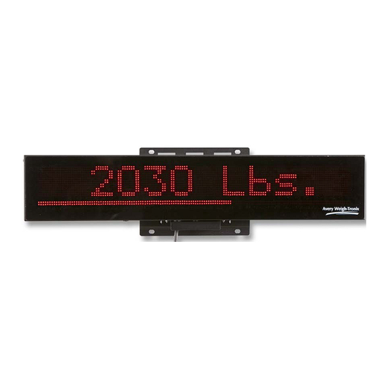
Scrolling 8 or 12 character full Alphanumeric Display. Ultra wide viewing angles up to 120 degrees. Multi interface support including: Avery Weigh-Tronix, Digi-Star and RS-232 Computer interfaces. Quad (single for XLR-6) LED digits offering bold and easy to read digits in direct sunlight. -
Page 10: Chapter 3 Installation
Installation 3.1 Mounting Brackets The XLR-6, XLR-8 and XLR-12 all have the same mounting bracket options and bolt pattern. The display is to be mounted on a solid mounting bracket or surface. The antenna wire at the bottom right side of the unit should never be cut or pinched during installation. The XLR remote display is equipped to support equipment that already has a preexisting rail mount type bracket which is commonly used (refer to section 3.2). -
Page 11: Adapter Mounting Plate
Figure 3.3 Adaptor Mounting Plate 3.3 Stainless Steel Shield It is highly recommended to use the optional Stainless Steel Shield with the XLR series remote display. The Stainless Steel shield will help keep dust and moisture off of the display to improve viewing quality. -
Page 12: Connecting The Display To Your Equipment
3.4.1 XLR-8 / XLR-12 Connections If you are connecting to Avery Weigh-Tronix or equipment that uses RS-232 communications, then you will be connecting to connector A (8 pin male). If you are using Digi-Star equipment then connect to connector B (8 pin female). Use only supplied cable assemblies from the manufacturer. -
Page 13: Xlr-6 Connections
3.4.2 XLR-6 Connections If you are connecting to Avery Weigh-Tronix or equipment that uses RS-232 communications, then you will be connecting to connector B (8 pin male). If you are using Digi-Star equipment then connect to connector A (8 pin female). Use only supplied cable assemblies from the manufacturer. -
Page 14: Cables
3.4.3 Cables Remote Display Cable with Power Supply Part Number Description AWT25-500473 10 ft / 3.1 m Cable Assembly, Serial RD with power AWT25-500477 30 ft / 9.2 m Cable Assembly, Serial RD with power Extension Cable Part Number Description AWT25-501728 10 ft / 3.1 m extension cable to use with Serial RD cable assembly. -
Page 15: Stainless Steel Shield Installation
3.5 Stainless Steel Shield Installation Loosen the screws (two on each side) on both ends of the XLR remote display. Refer to Figure 3.6 for screw location. Slide the shield in place so that the 4 slots in the shield ends slide over the screws. -
Page 16: Setup Of Awt Ag Indicators For Use With Xlr Displays
XLR remote display 3.6.1 Setup for 640 Series Indicators When using an XLR series remote display with an 640 Series indicator, an RS-232 serial port is required for the communication. Please verify that the 640 Series has one free serial port before continuing through the setup steps. See the illustration of the port connection in Figure 3.9. -
Page 17: Setup For 1040 And 2040 Series Indicators
640 Series service manual. 3.6.2 Setup for 1040 and 2040 Series Indicators When using the XLR Series remotes with the 1040 or 2040 indicators, a serial port is also required. This is the same connection as used in the 640 Series. Please reference... -
Page 18: Setup For 3060 Touch Screen Indicators
3.6.4 Setup for 3060 Touch Screen Indicators RS-232 Com port 2 or Com port 3 can run the XLR. If Feed Foreman is loaded on the 3060, Com port 3 must be used. 3060 touch screen RS-232 Port Settings for XLR Series Remotes Baud = 9600... -
Page 19: Setup For Digi-Star Indicators
3.6.6 Setup for Digi-Star Indicators When using the XLR Series remotes with Digi-Star indicators: Connect the XLR to the J-903 Remote port on the EZ-III indicator models (XLR series is not compatible with EZ-II indicator models.) Use the AWT Digi-Star interface cable from Avery Weigh-Tronix (PN AWT25-500928 or AWT25-500929) or the standard cable supplied by Digi-Star. -
Page 20: Chapter 4 Communicating With The Remote Display
Communicating With the Remote Display The XLR display automatically selects which type of communications protocol is being used. When connecting to Avery Weigh-Tronix or Digi-Star equipment, the display will automatically translate the display information correctly. No configuring of the display is required. -
Page 21: Transmit A Weight String
4.1.1 Transmit a Weight String Use numeric ASCII characters followed by a <CR> character. Weights are displayed from right to left. Example: To display “1000”, transmit: 1000<CR> 4.1.2 Transmit Status Characters Status characters may be embedded anywhere in the weight string to control the annunciator characters ‘G’... -
Page 22: Control Commands
“G 1234” “COTTON<CR> “ COTTON” “Pen 12<CR> “ Pen 12” “HOLD!<CR>@!<CR> “ HOLD!” flashing 3 times “Avery Weigh-Tronix<CR> “Avery Weigh-Tronix” scrolling @=3<CR>“Next Pen Number<CR> “Next Pen Number” slow scroll @^50<CR> Bar graph = 50% XLR-6, XLR-8 and XLR-12 Installation Instructions... -
Page 23: Connector Pin Outs
4.2 Connector Pin outs Avery Weigh-Tronix RS-232 (8 pin male) Pin 1 Not used Pin 2 RS232 Tx Pin 3 Not used Pin 4 RS232 Rx Pin 5 Pin 6 Pin 7 PWR ON Pin 8 +12V When using Connector A, 12V must be supplied to Pin 7 for the unit to turn on. -
Page 24: Chapter 5 Learn A New Transmitter Code (Channel 1)
Learn a New Transmitter Code (channel 1) Press the mode switch, pointed out in Figure 5.1. The green LED will start to flash quickly. Figure 5.1 Mode button on the remote receiver (PN AWT25-500927) While the green LED is flashing quickly (approximately 15 seconds), press the button on the remote transmitter shown in Figure 5.2. -
Page 25: Chapter 6 Specifications And Parts Lists
2.580” (65.5 mm) Weight: 7lbs (3.2 kg) Communication Avery Weigh-Tronix Connector: Voltage levels: RS-232 Input protocol: Avery Weigh-Tronix and Computer Control Baud Rate: 9600 N81 Remote power ON signal pin 7: 5V -12V DC Digi-Star Connector: Voltage Levels: 5V Synchronous Clocked Data... -
Page 26: Service Parts List
AWT20-504263 Gasket, XLR-8 Remote AWT20-508548 Cover, connector, XLR-8 AWT20-504832 Protective Stainless Steel Shield XLR-8 AWT20-504269 Display Card, 4 Digit XLR Series XLR-12 Scoreboard Remote Display AWT05-503509 Complete Remote Display, XLR-12 LED AWT20-504264 Enclosure, Rear XLR-12 LED Remote AWT20-504265 Enclosure, Front XLR-12 LED Remote AWT20-504266 Lens Assy, Non-Glare XLR-12 (adh. -
Page 27: Accessory Parts List
6.3 Accessory Parts List Part Number Description AWT25-500473 10 ft / 3.1 m Cable Assembly, Serial RD with power AWT25-500477 30 ft / 9.2 m Cable Assembly, Serial RD with power AWT25-501728 10 ft / 3.1 m extension cable to use with Serial RD cable assembly. This creates a disconnect point between the indicator in the cab's cable and the remote display's cable. - Page 28 XLR-6, XLR-8 and XLR-12 Installation Instructions...
- Page 30 Avery Weigh-Tronix USA 1000 Armstrong Dr. Fairmont MN 56031 USA Tel: 507-238-4461 Fax: 507-238-4195 Email: usinfo@awtxglobal.com www.agscales.com Avery Weigh-Tronix UK Foundry Lane, Smethwick, West Midlands, England B66 2LP Tel: +44 (0) 8453 66 77 88 To access manuals on Fax: +44 (0)121 224 8183 Email: info@awtxglobal.com...
Need help?
Do you have a question about the XLR Series and is the answer not in the manual?
Questions and answers