
Related Manuals for Vectornav VN-200

Summary of Contents for Vectornav VN-200
- Page 1 UM004 User manual VN-200 Beta VN -200 User Manual Firmware v0.1.7.x Rev 0.1.3 1/47...
-
Page 2: Table Of Contents
VN-200 SMD Serial (UART) Interface ..............10 2.1.3 VN-200 SMD Serial Peripheral Interface (SPI) ............10 2.1.4 VN-200 SMD Reset, SyncIn/Out, and Other General I/O Pins ........ 10 VN-200 Rugged Electrical ................11 2.2.1 VN-200 Rugged Power Supply ................12 2.2.2... - Page 3 VN-200 User Manual UM004 Numeric Formats ..................19 Single Precision Floating Points ..............19 Fixed-Point Numbers ................. 19 System Commands ..................20 4.4.1 Read Register Command..................20 4.4.2 Write Register Command ..................20 4.4.3 Write Settings Command ..................21 4.4.4 Restore Factory Settings Command ...............
- Page 4 VN-200 User Manual UM004 5.12.1 SyncInMode ......................38 5.12.2 SyncInEdge ......................38 5.12.3 SyncInSkipFactor ..................... 39 5.12.4 SyncOutMode ......................39 5.12.5 SyncOutPolarity....................... 39 5.12.6 SyncOutSkipFactor ....................39 5.12.7 SyncOutPulseWidth ....................40 5.13 Calibrated Sensor Measurements ............41 5.14 GPS Configuration .................. 42 5.15...
-
Page 5: Introduction
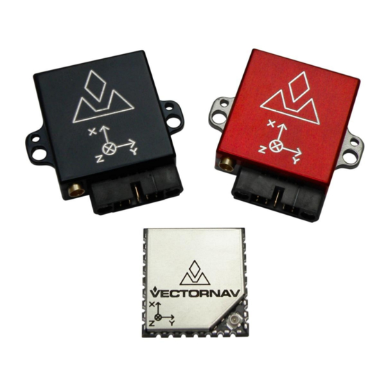
360 degrees of motion. Product Features The VN-200 is available in two different configurations, as a surface-mount sensor (VN-200 SMD), or as an enclosed sensor (VN-200 Rugged). The VN-200 Rugged provides a robust, precision anodized aluminum clamshell enclosure, ensuring precise alignment and calibration while still retaining the smallest possible footprint. -
Page 6: Surface-Mount Package
Single Power Supply: 3.2 to 5.5 V Communication Interface: Serial TTL & SPI Low Power Requirement: < 330 mW @ 3.3V Rugged Package The VN-200 Rugged consists of the VN-200 sensor installed in a robust precision aluminum enclosure. Features Precision aluminum enclosure ... -
Page 7: Vn-200 Rugged Gps/Ins Development Kit
(1) 6-foot USB connector cable Sensor Coordinate System The VN-200 uses a right-handed coordinate system: a positive yaw angle is defined as a positive right- handed rotation around the Z-axis; a positive pitch angle is defined as a positive right-handed rotation around the Y-axis;... -
Page 8: Specifications
VN-200 User Manual UM004 Specifications VN-200 Surface-Mount Sensor (SMD) Electrical Figure 2 – Pin assignments (top down view) www.vectornav.com 8/47... - Page 9 Used to reprogram the module. Must be left floating or set to low for normal REPRGM operation. Pull high on startup to set the VN-200 in reprogram mode. Internally held low with 10k resistor. Microcontroller reset line. Pull low for > 20 μs to reset MCU. Internally NRST pulled high with 10k.
-
Page 10: Vn-200 Smd Power Supply
The minimum operating supply voltage is 3.2 V and the absolute maximum is 5.5 V. 2.1.2 VN-200 SMD Serial (UART) Interface The serial interface on the VN-200 operates with 3 V TTL logic. Table 2 - Serial I/O Specifications Specification... -
Page 11: Vn-200 Rugged Electrical
VN-200 User Manual UM004 Output Frequency 1 Hz 200 Hz VN-200 Rugged Electrical Table 7 – VN-200 Rugged Pin Assignments Pin # Pin Name Description +5V (±0.5V) RS-232 voltage levels data output from the sensor. (Serial UART #1) RS-232 voltage levels data input to the sensor. (Serial UART #1) Output signal used for synchronization purposes. -
Page 12: Vn-200 Rugged Power Supply
The nominal power supply for the VN-200 Rugged is 5 V DC. The VN-200 Rugged internally has overvoltage protection set at a fixed voltage of 5.8 V. Upon an overvoltage event the protection circuitry will disable power to the VN-200 to reduce possibility of damage to the voltage regulator onboard the VN-200. -
Page 13: Vn-200 Surface-Mount Sensor (Smd) Dimensions
VN-200 User Manual UM004 VN-200 Surface-Mount Sensor (SMD) Dimensions Figure 4 – VN-200 PCB Footprint* * Measurements are in inches www.vectornav.com 13/47... -
Page 14: Vn-200 Rugged Dimensions
VN-200 User Manual UM004 VN-200 Rugged Dimensions Figure 5 – VN-200 Rugged Dimensions * Measurements are in inches Absolute Maximum Ratings Table 12 - Absolute Maximum Ratings Specification Input Voltage -0.3 V 5.5 V Operating Temperature -40 C 85 C... -
Page 15: Basic Communication
Sections (Section 4 & 5). Serial Interface On the serial interface, the VN-200 uses ASCII text for its command format. All commands start with a dollar sign, followed by a five character command, a comma, command specific parameters, an asterisk, a checksum, and a newline character. -
Page 16: Spi Interface
The SPI interface uses a lightweight binary message format. The start of a command is signaled by pulling the VN-200’s slave select pin (pin 23) low. Both the slave select line and clock are active low. The first byte transmitted to the module should be the command ID and then a variable number of bytes will follow dependent on the type of command specified. - Page 17 Table 21 in Section 5. At the same time zeros are received by the master, assuming no previous SPI command was sent to the VN-200 since reboot. On the second transaction the master sends the command to read register 13.
- Page 18 VN-200. The response received on the second transaction will contain the most up to date values for the desired register.
-
Page 19: Communication Protocol
The registers that use fixed point representation and their associated formatting are listed below. It is important to note that all numeric calculations onboard the VN-200 are performed with 32-bit or 64-bit IEEE floating-point numbers. For the sake of simplifying the output stream, some of these numbers are displayed in ASCII as fixed point as described below. -
Page 20: System Commands
Read Register Command This command allows the user to read any of the registers on the VN-200 module (see Section 5 for the list of available registers). The only required parameter is the ID of the register to be read. The first parameter of the response will contain the same register ID followed by a variable number of parameters. -
Page 21: Write Settings Command
This command will write the current register settings into non-volatile memory. Once the settings are stored in non-volatile (Flash) memory, the VN-200 module can be power cycled or reset, and the register will be reloaded from non-volatile memory. The module can always be reset to the factory settings by issuing the Restore Factory Settings command (Section 0) or by pulling pin 7 (Tare/Restore) high during reset. -
Page 22: Reset Command
If no values are stored in non-volatile memory, the device will default to factory settings. Also upon reset the VN-200 will re-initialize its Kalman filter, thus the filter will take a few seconds to completely converge on the correct attitude and correct for gyro bias. -
Page 23: System Error Codes
UM004 System Error Codes In the event of an error, the VN-200 will output $VNERR, followed by an error code. The possible error codes are listed in the table below with a description of the error. Table 20 – Error Codes... -
Page 24: System Registers
UM004 System Registers The VN-200 module contains a collection of registers used for configuring the module and accessing the data it produces. These registers may be read or written to using the Read Register and Write Register commands (Sections 4.4.1 and 4.4.2). When the module is rebooted or power-cycled, values written to the registers will revert back to their previous values unless a Write Settings command has been issued (Section 4.4.3) to save the registers to non-volatile memory. -
Page 25: User Tag Register
VN-200 User Manual UM004 User Tag Register User Tag Register ID : Firmware : v0.1 and up Access : Read / Write User assigned tag register. Any values can be assigned to this register. They will be Comment : stored to flash upon issuing a write settings command. -
Page 26: Model Number Register
VN-200 User Manual UM004 Model Number Register Model Number Register ID : Firmware : v0.1 and up Access : Read Only Comment : Model Number Size (Bytes): Example Serial Read Register $VNRRG,01,VN-200T-DEV*77 Response: Byte Number Offset Name Format Unit Description Product Name Product name. -
Page 27: Hardware Revision Register
VN-200 User Manual UM004 Hardware Revision Register Hardware Revision Register Register ID : Firmware : v0.1 and up Access : Read Only Comment : Hardware revision. Size (Bytes): Example Serial Read Register $VNRRG,02,6*6B Response: Byte Number Offset Name Format Unit... -
Page 28: Serial Number Register
VN-200 User Manual UM004 Serial Number Register Serial Number Register ID : Firmware : v0.1 and up Access : Read Only Comment : Serial Number Size (Bytes): Example Serial Read Register $VNRRG,03,0100011981*5D Response: Byte Number Offset Name Format Unit Description... -
Page 29: Firmware Version Register
VN-200 User Manual UM004 Firmware Version Register Firmware Version Register Register ID : Firmware : v0.1 and up Access : Read Only Comment : Firmware version. Size (Bytes): Example Serial Read Register $VNRRG,04,0.1.7.0*73 Response: Byte Number Offset Name Format Unit... -
Page 30: Serial Baud Rate Register
If the second parameter is not provided then the response will not include this parameter. Upon receiving a baud rate change request, the VN-200 will send the response prior to changing the baud rate. -
Page 31: Async Data Output Type Register
VN-200 User Manual UM004 Async Data Output Type Register Asynchronous Data Output Type Register ID : Firmware : v0.1 and up Access : Read / Write Comment : Asynchronous data output type. Size (Bytes): Example Serial Read Register $VNRRG,06,0*69 Response:... -
Page 32: Async Data Output Frequency Register
VN-200 User Manual UM004 Async Data Output Frequency Register Asynchronous Data Output Frequency Register ID : Firmware : v0.1 and up Access : Read / Write Comment : Asynchronous data output frequency. Size (Bytes): Example Serial Read Register $VNRRG,07,40*5C Response:... -
Page 33: Magnetic And Gravity Reference Vectors
VN-200 User Manual UM004 Magnetic and Gravity Reference Vectors Magnetic and Gravity Reference Vectors Register ID : Firmware : v0.1 and up Access : Read / Write Comment : Magnetic and gravity reference vectors. Size (Bytes): Example Serial Read $VNRRG,21,1,0,1.8,0,0,-9.79375*53... -
Page 34: Reference Frame Rotation
INS output. After setting the reference frame rotation register to its new value, send a write settings command and then reset the VN-200. This will allow the INS filter to startup with the newly set reference frame rotation. -
Page 35: Communication Protocol Control
Register ID : Firmware : v0.1 and up Access : Read / Write Contains parameters that control settings relating to the communication protocol Comment : used to communicate with the VN-200. Size (Bytes): Example Serial Read Register $VNRRG,30,2,0,0,0,1,0,1*6E Response: Byte Number... -
Page 36: Serialstatus
VN-200 User Manual UM004 5.11.2 SerialStatus The SerialStatus field provides a means of tracking real-time status information pertaining to the overall state of the sensor measurements and onboard filtering algorithm. This information is very useful in situations where action must be taken when certain crucial events occur, such as the detection of gyro saturation or magnetic interference. -
Page 37: Serialchecksum
ErrorMode This field controls the type of action taken by the VN-200 when an error event occurs. If the send error mode is enabled then a message similar to the one shown below will be sent on the serial bus when an error event occurs. -
Page 38: Synchronization Control
200 Hz. If the SyncIn event is used to control the ADC sampling, the SyncIn event must be kept always at 200 Hz. If set to ASYNC, the VN-200 will output asynchronous serial messages upon each trigger event. -
Page 39: Syncinskipfactor
VN-200 User Manual UM004 5.12.2 SyncInEdge The SyncInEdge register controls the type of edge the signal is set to trigger on. The factory default state is to trigger on a rising edge. Table 33 – SyncInEdge Mode Value Description Trigger on rising edge Trigger on falling edge 5.12.3... -
Page 40: Syncoutpulsewidth
VN-200 User Manual UM004 5.12.7 SyncOutPulseWidth The SyncOutPulseWidth field controls the desired width of the SyncOut pulse. www.vectornav.com 40/47... -
Page 41: Calibrated Sensor Measurements
VN-200 User Manual UM004 5.13 Calibrated Sensor Measurements Calibrated Sensor Measurements Register ID : Firmware : v0.1 and up Access : Read Only Comment : Calibrated measurements from all onboard sensors. Size (Bytes): Example Serial Read $VNRRG,54,+01.5656,-00.2630,+01.5138,-00.888,+00.051,- Register Response: 09.814,+00.004525,+00.000271,+00.021949,+20.4,+00098.968*58... -
Page 42: Gps Configuration
VN-200 User Manual UM004 5.14 GPS Configuration GPS Configuration Register ID : Firmware : v0.1 and up Access : Read / Write Comment : Size (Bytes): Example Serial Read $VNRRG,55,2,0,0,0*71 Register Response: Byte Number Offset Name Format Unit Description GPS mode. -
Page 43: Gps Antenna Offset
GPS Antenna Offset Register ID : Firmware : v0.1 and up Access : Read Only Configures the position offset of the GPS antenna from the VN-200 in the vehicle Comment : reference frame. Size (Bytes): Example Serial Read $VNRRG,57,0,0,0*6D Register Response:... -
Page 44: Gps Solution
VN-200 User Manual UM004 5.16 GPS Solution GPS Solution Register ID : Firmware : v0.1 and up Access : Read / Write Comment : Available at 5 Hz only. Size (Bytes): Example Serial Read $VNRRG,58,333733.000159,1694,3,05,+32.95622080,-096.71415970,+00169.457,- Register Response: 000.850,-000.580,-002.860,+005.573,+003.644,+009.760,+003.320,2.00E-08*0E Byte Number... -
Page 45: Ins Solution
VN-200 User Manual UM004 5.17 INS Solution INS Solution Register ID : Firmware : v0.1 and up Access : Read Only Comment : Size (Bytes): Example Serial Read $VNRRG,63,333811.902862,1694,0004,+009.500,-004.754,-000.225,+32.95602815,- Register Response: 096.71424297,+00171.195,-000.840,-000.396,-000.109,07.8,01.6,0.23*5F Byte Number Offset Name Format Unit Description Time GPS time of week in seconds. -
Page 46: System Registers - Default Factory State
System Registers - Default Factory State The following table details the VN-200’s settings as it is delivered from the factory. These settings may be restored by issuing a Restore Factory Settings command (Section 0) or by using the Restore Factory Settings signal pins. - Page 47 No license to any intellectual property, expressed or implied, is granted under this document. If any part of this document refers to any third party products or services it shall not be deemed a license grant by VectorNav for the...
Need help?
Do you have a question about the VN-200 and is the answer not in the manual?
Questions and answers