Table of Contents
Advertisement
Advertisement
Table of Contents

Related Manuals for Vectornav VN-200

Summary of Contents for Vectornav VN-200
- Page 1 VN-200 Development Kit Quick Start Guide...
- Page 2 200 configured and operational. It will also introduce some common operations performed with the sensor. For more detailed information please refer to the VN-200 User Manual, a copy of which is provided with the Development Kit and is also available online at www.vectornav.com/support.
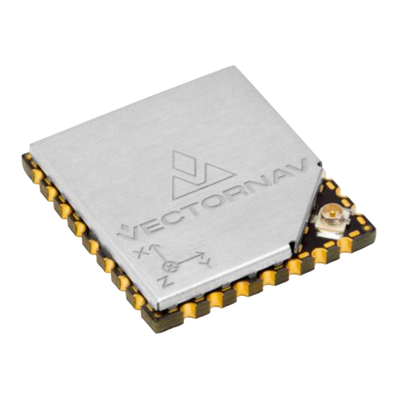
- Page 3 The VN-200 is a miniature, surface-mount, high-performance GPS-Aided Inertial Navigation System (GPS/INS). Incorporating the latest solid-state MEMS sensor technology, the VN-200 combines a set of 3-axis accelerometers, 3-axis gyros, 3-axis magnetometer, a barometric pressure sensor, a 50-channel L1 GPS receiver, as well as a 32-bit processor into a miniature surface-mount or standalone module.
- Page 4 Mounting the VN-200 You may mount the VN-200 to the vehicle or platform in any orientation. If the VN-200 axes do not align with the desired vehicle or platform axes then a Reference Frame Rotation will be required to remap the attitude, angular rates, acceleration, and other data to the desired frame (see page 9).
- Page 5 Ground planes can be any thin piece of metal (even foil) Mounting the GPS Antenna The VN-200 requires connection to an active GPS antenna, mounted with a clear view of the sky. In order for the GNSS Compass to function optimally both antennas must: •...
- Page 6 Time: +30 sec GPS Fix acquired. Local magnetic declination applied. VN-200 still operating as AHRS. The VN-200 needs to exceed 5 m/s for more than 1 second to start dynamic alignment During dynamic alignment accel and GPS data are correlated to produce yaw estimate.
- Page 7 VN-200 Setup Reference Frame Rotation The VN-200 may be mounted in any orientation on the vehicle or platform. The Refence Frame Rotation is a 3 x 3 rigid rotation matrix that will map the sensor axes to the vehicle axes, this will enable the VN-200 to output attitude, angular rates, acceleration, and other data in the vehicle reference frame.
- Page 8 IMU. The VN- 200 defines the Antenna A offset as the distance from the VN-200 to Antenna A in the X, Y, & Z directions defined by the Sensor Frame.
- Page 9 Settings command was issued. A Restore Factory Settings command will reset the configuration to the default settings. A copy of the Control Center GUI is included on the CD in the VN-200 Development Kit. Please also regularly check our website for the latest version of the software.
- Page 10 PC running our Control Center GUI to gain familiarity with the available configuration options and features. 1. Attach the USB or Serial Adapter Cable to the VN-200 using the cable tool provided in the Development Kit. For the VN-200 Development...
- Page 11 The Simple Ref Frame Calc will step you through aligning the VN-200 axes with the vehicle axes. There are three (3) steps: a. What axis of the VN-200 aligns with the forward axis of the vehicle? b. What axis of the VN-200 aligns with the downward axis of the vehicle? c.
- Page 12 Use the 3D View to confirm the orientation of the VN-200 matches your physical installation. 10-0003-R3 Copyright © 2019 VectorNav Technologies, LLC...
- Page 13 It is important to issue a Write Settings followed by a Reset command after inputting the GNSS Compass Baseline measurements to ensure the VN-200 initializes on the correct values. Right-click on Write Settings in the Commands Window and then click Execute Command. Next, right-click on Reset and then click Execute Command.
- Page 14 Monitoring VN-200 Startup Control Center will poll the VN-200 and display the INS Mode, GNSSFix status flags in the Sensor Status window. It will also provide details of the number of satellites used from Position, Velocity and Timing (PVT) solution.
- Page 15 Move away from obstructions or large buildings Ensure antenna is mounted directly to ground plane 3. The VN-200 is not getting into INS Mode 2 The VN-200 will only dynamically align with sufficient motion. The vehicle/platform needs to exceed 5 m/s in order to dynamically align 4.
- Page 16 VN-200 Installation and Setup Checklist Description Yes/No VN-200 Mounting Is the VN-200 rigidly mounted? Are the cables strain relieved? Do you need a reference frame rotation? |_ _ GNSS Antenna Mounting Is the GPS antenna rigidly mounted? ...
- Page 17 Connect the VN-200 to Control Center Is GPS Fix: True Is INS Mode: 1 Has your platform/vehicle exceed 5m/s Is INS Mode: 2 10-0003-R3 Copyright © 2019 VectorNav Technologies, LLC...
- Page 18 Additional References • VectorNav VN-200 User Manual (UM0004) www.vectornav.com/support/manuals • VectorNav Development Tools o Control Center o C/C++ Library o .NET Library o Embedded Firmware Library o MATLAB Development Library o EAGLE PCB Parts Library www.vectornav.com/support/downloads • Overview of Inertial Sensor Technology www.vectornav.com/support/library...
Need help?
Do you have a question about the VN-200 and is the answer not in the manual?
Questions and answers