
Subscribe to Our Youtube Channel
Related Manuals for Future Design FDC-9300

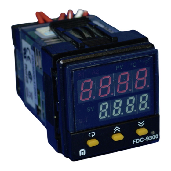
Summary of Contents for Future Design FDC-9300
- Page 1 User's Manual User's Manual FDC-9300 FDC-9300 Self-Tune Fuzzy / PID Self-Tune Fuzzy / PID Process / Temperature Controller Process / Temperature Controller...
-
Page 2: Table Of Contents
CONTENTS Page No Page No Chapter 1 Overview Chapter 1 Overview 1-1 Features ------------------------------------------------------------------------- 1-1 Features ------------------------------------------------------------------------- 1-2 Ordering Code ---------------------------------------------------------------- 1-2 Ordering Code ---------------------------------------------------------------- 1-3 Programming Port and DIP Switch --------------------------------------- 1-3 Programming Port and DIP Switch --------------------------------------- 1-4 Keys and Displays ------------------------------------------------------------ 1-4 Keys and Displays ------------------------------------------------------------ 1-5 Menu Overview -------------------------------------------------------------- 1-5 Menu Overview --------------------------------------------------------------... -
Page 3: Chapter 1 Overview
OEM's as it is easy to configure menu to suit the specific application. FDC-9300 is powered by 11-28 or 90 - 264 VDC / AC supply, incorporating a 2 amp. FDC-9300 is powered by 11-28 or 90 - 264 VDC / AC supply, incorporating a 2 amp. -
Page 4: Ordering Code
CM94-5 = Isolated 0 - 10V Retransmission Module RS-232 Network RS-232 Network CC94-1 = RS-232 Interface Cable (2M) CC94-1 = RS-232 Interface Cable (2M) UM9300 2.0 = FDC-9300 User's Manual UM9300 2.0 = FDC-9300 User's Manual UM9300 2.0 UM9300 2.0... -
Page 5: Programming Port And Dip Switch
1 3 Programming Port and DIP Switch 1 3 Programming Port and DIP Switch Access Hole Rear Terminal Front Panel Figure 1.2 Access Hole Figure 1.2 Access Hole Overview Overview Control Chassis Bottom View The programming port is used to connect to The programming port is used to connect to P10A hand-held programmer for automatic P10A hand-held programmer for automatic... -
Page 6: Keys And Displays
Output 1 output value etc. output value etc. Indicator Indicator 3 Silicone Rubber Buttons 3 Silicone Rubber Buttons FDC-9300 for ease of control setup for ease of control setup and set point adjustment. and set point adjustment. Program Version Program Version Figure 1.4 Front Panel Description... -
Page 7: Menu Overview
1 5 Menu Overview 1 5 Menu Overview User User PV Value Menu Menu SV Value SEL1 Press Press to enter Setup Mode. Press to enter Setup Mode. Press to select parameter. The upper to select parameter. The upper SEL2 SEL3 display indicates the parameter symbol, and the lower display indicates the display indicates the parameter symbol, and the lower display indicates the... -
Page 8: 6 Parameter Description
1 6 Parameter Description Table 1.4 Parameter Description Table 1.4 Parameter Description Display Display Parameter Parameter Contained Contained Basic Basic Parameter Parameter Default Default Range Format Format Description Description Function Function Notation Notation Value Value 100.0 C Set point 1 High: SP1L SP1H... - Page 9 Table 1.6 Parameter Description ( continued 2/7 ) Table 1.6 Parameter Description ( continued 2/7 ) Display Display Parameter Parameter Basic Basic Parameter Parameter Default Default Contained Contained Range Format Format Description Description Function Function Notation Notation Value Value Address Assignment of Digital High: ADDR Low:...
- Page 10 Table 1.6 Parameter Description ( continued 3/7 ) Table 1.6 Parameter Description ( continued 3/7 ) Display Display Parameter Parameter Basic Basic Parameter Parameter Default Contained Contained Range Format Format Description Description Value Function Function Notation Notation C type thermocouple P type thermocouple PT 100 ohms DIN curve PT 100 ohms JIS curve...
- Page 11 Table 1.6 Parameter Description ( continued 4/7 ) Table 1.6 Parameter Description ( continued 4/7 ) Display Display Parameter Parameter Basic Basic Parameter Parameter Default Default Contained Contained Range Format Format Description Description Function Function Notation Notation Value Value 0 - 20 mA current module 0 - 1V voltage module Output 1 Signal Type 0 - 5V voltage module...
- Page 12 Table 1.6 Parameter Description ( continued 5/7 ) Table 1.6 Parameter Description ( continued 5/7 ) Display Display Parameter Parameter Basic Basic Parameter Parameter Default Default Contained Contained Range Format Format Description Description Function Function Notation Notation Value Value Alarm output OFF as unit fails Alarm 1 Failure Transfer A1FT Mode...
- Page 13 Table 1.6 Parameter Description Table 1.6 Parameter Description Display Display Parameter Parameter Basic Basic Parameter Parameter Contained Contained Default Default Range Format Format Description Description Function Function Notation Notation Value Value Use SP1 or SP2 (depends on EIFN) as set point Use minute ramp rate as set point Use hour ramp rate as set point SPMD...
- Page 14 Table 1.6 Parameter Description ( continued 7/7 ) Table 1.6 Parameter Description ( continued 7/7 ) Display Display Parameter Parameter Basic Basic Parameter Parameter Default Default Contained Contained Range Format Format Description Description Function Function Notation Notation Value Value Cold Junction Gain Low: -199.9 199.9...
-
Page 15: Chapter 2 Installation
Chapter 2 Installation Chapter 2 Installation Dangerous voltages capable of causing death are sometimes Dangerous voltages capable of causing death are sometimes present present in this instrument. Before installation or beginning any troubleshooting in this instrument. Before installation or beginning any troubleshooting procedures the power to all equipment must be switched off and isolated. -
Page 16: Wiring Precautions
2 3 Wiring Precautions 2 3 Wiring Precautions Before wiring, verify the label for correct model number and options. Switch Before wiring, verify the label for correct model number and options. Switch off the power while checking. off the power while checking. Care must be taken to ensure that maximum voltage rating specified on the Care must be taken to ensure that maximum voltage rating specified on the label are not exceeded. -
Page 17: Power Wiring
2 4 Power Wiring 2 4 Power Wiring The controller is supplied to operate at 11-28 VAC / VDC or 90-264VAC.Check The controller is supplied to operate at 11-28 VAC / VDC or 90-264VAC.Check that the installation voltage corresponds with the power rating indicated on the that the installation voltage corresponds with the power rating indicated on the product label before connecting power to the controller. -
Page 18: Thermocouple Input Wiring
2 6 Thermocouple Input Wiring 2 6 Thermocouple Input Wiring IThermocouple input connections are shown in Figure 2.5. The correct type of IThermocouple input connections are shown in Figure 2.5. The correct type of thermocouple extension lead-wire MUST be used for the entire distance from thermocouple extension lead-wire MUST be used for the entire distance from thermocouple sensor to connection to the controller. -
Page 19: Linear Dc Input Wiring
2 8 Linear DC Input Wiring 2 8 Linear DC Input Wiring DC linear voltage and linear current connections for input 1 are shown in Figure DC linear voltage and linear current connections for input 1 are shown in Figure 2.7 and Figure 2.8 . -
Page 20: Output 1 Wiring
2 10 Output 1 Wiring 2 10 Output 1 Wiring Max. 2A Max. 2A Resistive Resistive 0 - 20mA, 0 - 20mA, Load 120V/240V 120V/240V Load 4 - 20mA 4 - 20mA Mains Supply Mains Supply Maximum Load 500 ohms Maximum Load 500 ohms Relay Output Relay Output... -
Page 21: Output 2 Wiring
2 11 Output 2 Wiring 2 11 Output 2 Wiring Max. 2A Max. 2A Resistive Resistive 0 - 20mA, 0 - 20mA, Load 120V/240V 120V/240V Load 4 - 20mA 4 - 20mA Mains Supply Mains Supply Maximum Load Maximum Load 500 Ohm max 500 Ohm max Figure 2.13... -
Page 22: Event Input Wiring
2 12 Event Input wiring 2 12 Event Input wiring Figure 2.14 Figure 2.14 Event Input Wiring Event Input Wiring Switch Input Switch Input Open Collector Open Collector Input Input The event input can accept a switch signal as well as an open collector signal. The The event input can accept a switch signal as well as an open collector signal. -
Page 23: Rs-485
2 15 RS-485 2 15 RS-485 Figure 2.17 Figure 2.17 RS-485 Wiring RS-485 Wiring RS-485 to RS-232 RS-485 to RS-232 network adaptor network adaptor SNA10A or SNA10A or SNA10B SNA10B RS-232 RS-485 Twisted-Pair Wire Twisted-Pair Wire Max. 247 units can be linked Max. -
Page 24: Rs-232
RS-232 port CC94-1 Note: If the FDC-9300 is configured for RS-232 communication, the EI ( Event If the FDC-9300 is configured for RS-232 communication, the EI ( Event Input ) is disconnected internally. The unit can no longer perform event Input ) is disconnected internally. -
Page 25: Chapter 3 Programming Special Functions
" sorry " to you. The FDC-9300 has the flexibility for you to select those will say " sorry " to you. The FDC-9300 has the flexibility for you to select those... -
Page 26: Dwell Timer
3 2 Dwell Timer 3 2 Dwell Timer Alarm 1 or alarm 2 can be configured as a dwell timer by selecting TIMR for A1FN or A2FN Alarm 1 or alarm 2 can be configured as a dwell timer by selecting TIMR for A1FN or A2FN but not BOTH. -
Page 27: Failure Transfer
3 4 Failure Transfer 3 4 Failure Transfer Failure Mode Occurs as : Failure Mode Occurs as : The controller will enter The controller will enter failure mode failure mode as one of the following conditions occurs: as one of the following conditions occurs: 1. -
Page 28: Bumpless Transfer
3 6 Bumpless Transfer 3 6 Bumpless Transfer The bumpless transfer function is available for output 1 and output 2 ( provided The bumpless transfer function is available for output 1 and output 2 ( provided Bumpless Transfer Setup : Bumpless Transfer Setup : that OUT2 is configured as COOL ). -
Page 29: Self-Tuning
3 7 Self 3 7 Self Tuning Tuning The Self-tuning which is designed by using an The Self-tuning which is designed by using an innovative algorithm innovative algorithm provides provides Self-tune Menu Self-tune Menu an alternative option for tuning the controller. It is activated as soon as SELF an alternative option for tuning the controller. -
Page 30: Auto-Tuning
3 8 Auto 3 8 Auto Tuning Tuning The auto-tuning process is performed at set point. The auto-tuning process is performed at set point. The process will oscillate around the set point during tuning process. The process will oscillate around the set point during tuning process. Set a set point to a lower value if overshooting beyond the normal Set a set point to a lower value if overshooting beyond the normal process value is likely to cause damage. - Page 31 Auto-tuning Auto-tuning Auto-tuning Auto-tuning Begins Begins Complete Complete Waiting Waiting Warm-up Warm-up Cycle Cycle Learning Cycle Learning Cycle New PID Cycle New PID Cycle Cycle Cycle =2 Integral =2 Integral Time Time Figure 3.4 Figure 3.4 Set Point Set Point Auto-tuning Procedure Auto-tuning Procedure Pre-tune Stage...
-
Page 32: Manual Tuning
3 9 Manual Tuning 3 9 Manual Tuning In certain applications ( very few ) using both self-tuning and auto-tuning to In certain applications ( very few ) using both self-tuning and auto-tuning to tune a process may be inadequate for the control requirement, then you tune a process may be inadequate for the control requirement, then you can try manual tuning. - Page 33 The PBu is called the The PBu is called the Ultimate P Band Ultimate P Band and the period of oscillation Tu is and the period of oscillation Tu is called the called the Ultimate Period Ultimate Period in the flow chart of Figure 3.5 . When this occurs, in the flow chart of Figure 3.5 .
- Page 34 Figure 3.25 shows the effects of PID adjustment on process response. Figure 3.25 shows the effects of PID adjustment on process response. P action P action PB too narrow PB too narrow Perfect Set point Set point Figure 3.7 Effects of PID Figure 3.7 Effects of PID Adjustment Adjustment...
-
Page 35: Pump Control
3 10 Pump Control 3 10 Pump Control Pump Control function is one of the unique features of FDC-9300. Using this Pump Control function is one of the unique features of FDC-9300. Using this PUMP: A Cost Effective PUMP: A Cost Effective function the pressure in a process can be controlled excellently. -
Page 36: Sleep Mode
Programming Guide: Programming Guide: 1. Perform auto-tuning to the system under such condition that the material 1. Perform auto-tuning to the system under such condition that the material ( ie. pressure ) is exhausted at typical rate. A typical value for PB1 is about ( ie. -
Page 37: Heater Break
3 13 Heater Break Alarm 3 13 Heater Break Alarm Heater Break Alarm 1 Heater Break Alarm 1 A current transformer ( parts No. A current transformer ( parts No. CT94-1 CT94-1 ) should be installed to detect the ) should be installed to detect the Setup : IN2 = CT Setup : IN2 = CT heater current if a heater break alarm is required. -
Page 38: Chapter 4 Calibration
Chapter 4 Calibration Chapter 4 Calibration Do not proceed through this section unless there is a definite need to Do not proceed through this section unless there is a definite need to re-calibrate the controller. Otherwise, all previous calibration data will be re-calibrate the controller. - Page 39 RTD input RTD input and 13 according to the connection shown below: and 13 according to the connection shown below: 100 ohms FDC-9300 Figure 4.1 Figure 4.1 RTD Calibration RTD Calibration Press the scroll key for at least 5 seconds then release scroll key. The Press the scroll key for at least 5 seconds then release scroll key.
- Page 40 T/C type and set for F or C. Input type TC input TC input programming does bot effect the cold junction calibration procedure. programming does bot effect the cold junction calibration procedure. Calibrator FDC-9300 Figure 4.2 Figure 4.2 K-TC Cold Junction Cold Junction...
- Page 41 Perform step 1 as stated to enter into calibration mode. Perform step 1 as stated to enter into calibration mode. Press the scroll key until Press the scroll key until With With on the display and simulator simulating the K t/c, on the display and simulator simulating the K t/c, 0.00 C degree input signal, use the up/down keys until value 0.00 0.00 C degree input signal, use the up/down keys until value 0.00...
-
Page 42: Chapter 5 Error Codes And Troubleshooting
Expand the rear edge of the housing by using a tool. Pull out the PCB from the housing. using a tool. Pull out the PCB from the housing. Figure 5.1 Figure 5.1 Dismantling the Controller Dismantling the Controller FDC-9300 UM9300 2.0 UM9300 2.0... - Page 43 Table 5.1 Error Codes and Corrective Actions Table 5.1 Error Codes and Corrective Actions Display Error Error Description Corrective Action Symbol Code Illegal setup values been used: PV1 is used for both PVMD Check and correct setup values of PVMD and SPMD. PV and SPMD.
- Page 44 Table 5.2 Common Failure Causes and Corrective Actions Table 5.2 Common Failure Causes and Corrective Actions Symptom Probable Causes Corrective Actions - Clean contact area on PCB -Bad connection between PCB & keypads 1) Keypad no function - Replace keypads - No power to instrument - Check power line connections 2) LED's will not light...
-
Page 45: Chapter 6 Specifications
Chapter 6 Specifications Chapter 6 Specifications Power Input 2 Input 2 90 264 VAC, 47 63 Hz, 15VA, 7W maximum 90 264 VAC, 47 63 Hz, 15VA, 7W maximum Resolution : Resolution : 18 bits 18 bits 11 26 VAC / VDC, 15VA, 7W maximum 11 26 VAC / VDC, 15VA, 7W maximum Sampling Rate : Sampling Rate :... - Page 46 Linear Output Linear Output Resolution : Resolution : 15 bits 15 bits Resolution : Resolution : 15 bits 15 bits Accuracy : Accuracy : +/-0.05 % of span +/-0.0025 % / C +/-0.05 % of span +/-0.0025 % / C Output Regulation : Output Regulation : 0.01 % for full load change...
- Page 47 Environmental & Physical Environmental & Physical Operating Temperature : Operating Temperature : -10 C to 50 C -10 C to 50 C Storage Temperature : Storage Temperature : -40 C to 60 C -40 C to 60 C Humidity : Humidity : 0 to 90 % RH ( non-condensing ) 0 to 90 % RH ( non-condensing )
-
Page 48: Menu Existence / Your Settings
A 1 Menu Existence Conditions A 1 Menu Existence Conditions Menu Existence Conditions Table (1/3) Menu Existence Conditions Table (1/3) Your Your Parameter Parameter Menu Existence Conditions Existence Conditions Settings Settings Notation Notation Exists unconditionally Exists unconditionally TIME Exists if A1FN selects TIMR or A2FN selects TIMR Exists if A1FN selects TIMR or A2FN selects TIMR A1SP Exists if A1FN selects PV1H, PV1L, PV2H, PV2L, P12H, P12L, D12H or D12L... - Page 49 Menu Existence Conditions Table ( continued 2/3 ) Menu Existence Conditions Table ( continued 2/3 ) Your Your Parameter Parameter Menu Settings Settings Notation Notation FUNC Exists unconditionally Exists unconditionally COMM Exists if FUNC selects FULL Exists if FUNC selects FULL PROT ADDR BAUD...
- Page 50 Menu Existence Conditions Table ( continued 3/3 ) Menu Existence Conditions Table ( continued 3/3 ) Your Your Parameter Parameter Menu Existence Conditions Existence Conditions Settings Settings Notation Notation A1FN Exists unconditionally Exists unconditionally Exists if A1FN selects DEHI, DELO, DBHI, DBLO, PV1H, PV1L, PV2H, PV2L, P12H, P12L, Exists if A1FN selects DEHI, DELO, DBHI, DBLO, PV1H, PV1L, PV2H, PV2L, P12H, P12L, A1MD D12H, D12L, LB or SENB...
-
Page 51: Warranty
Future Design Controls products. products for their application or use of Future Design Controls products. Future Design Controls shall not be liable for any damages or losses, Future Design Controls shall not be liable for any damages or losses,... - Page 52 Future Design Controls Future Design Controls 7524 West 98th Place, P .O. Box 1196 7524 West 98th Place, P .O. Box 1196 Bridgeview, IL. 60455 USA Bridgeview, IL. 60455 USA 888.751.5444 - Office 888.751.5444 - Office 888.307.8014 - Fax 888.307.8014 - Fax 866.342.5332 - Technical Support...
Need help?
Do you have a question about the FDC-9300 and is the answer not in the manual?
Questions and answers