Table of Contents
Advertisement
Quick Links
Advertisement
Table of Contents

Related Manuals for E-FLITE Byp Yak


Summary of Contents for E-FLITE Byp Yak
- Page 1 Byp Yak Assembly Manual...
-
Page 2: Table Of Contents
Required Tools and Adhesives ........5 Optional Accessories ..........5 rigid fuselage giving you more precision control. Using the Manual ............6 From super slow to top airspeed, flying the Byp Yak features Warning ..............6 Before Starting Assembly ..........6 a great combination of smoothness and precision, helping Note on Lithium Polymer Batteries .........6... -
Page 3: Specifications
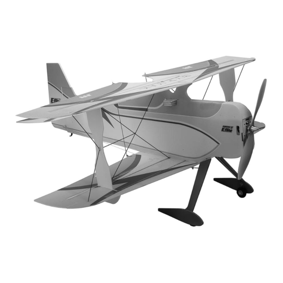
Specifications Contents of Kit/Parts Layout Wingspan: 32 in (815mm) Large Replacement Parts: Length: 31.25 in (795mm) EFL2326 Wing Set w/Struts Wing Area: 490 sq in (32 sq dm) EFL2327 Fuselage Weight w/o Battery: 9.5–10 oz (270–285 g) EFL2328 Tail Assembly Weight w/Battery: 10.5–11.5 oz (300–325 g) EFL2331... -
Page 4: Quique Somenzini's Competition Radio Equipment
Listed below is the exact radio equipment that Quique and three sub-micro servos. You can choose to purchase a Somenzini uses when flying the Byp Yak in competitions. In complete radio system that includes all of these items or, if... -
Page 5: Important Information About Motor Selection
We recommend you use the E-flite brushless outrunner ™ EFLA250) motor Quique Somenzini uses on his Byp Yak. All of our EFLA251 Hex Wrench: 3/32" (or included with flight tests were done using the motor listed below with the EFLA250) Li-Po battery listed below. -
Page 6: Using The Manual
Before Starting Assembly This manual is divided into sections to help make assembly Before beginning the assembly of your Byp Yak, remove easier to understand, and to provide breaks between each each part from its bag for inspection. Closely inspect the major section. -
Page 7: Safety Precautions
(i) repair or (ii) replace, any product determined By the act of use, setup or assembly, the user accepts all by Horizon Hobby, Inc. to be defective. In the event of a resulting liability. defect, these are your exclusive remedies. -
Page 8: Inspection Or Repairs
Please note Horizon Hobby, Inc. directly. This will enable Horizon to that original boxes may be included, but are not designed better answer your questions and service you in the event to withstand the rigors of shipping without additional that you may need any assistance. - Page 9 You will be billed for any return freight for non-warranty repairs. Please advise us of your preferred method of payment. Horizon Hobby accepts money orders and cashiers checks, as well as Visa, MasterCard, American Express, and Discover cards. If you choose to pay by credit card, please include your credit card number and expiration date.
-
Page 10: Wing Installation
Wing Installation Required Parts • Fuselage • Wing strut (2) • Lower wing • Upper wing • Strut reinforcement disk (14) • .045” x 6" (1.15mm x 153mm) carbon rod (6) • .045” x 13" (1.15mm x 330mm) carbon rod (2) •... - Page 11 3. Locate the wing struts. Use a sharp hobby 2. Test fit the lower wing to the fuselage. Place the knife to remove the lower sections from the wing onto the fuse bottom, aligning the servo main section. holes in the wing with the servo holes in the fuselage.
- Page 12 4. Position the wing strut in the hole closest to the 5. Place the top wing onto a flat surface. Position aileron of the bottom wing. It may be necessary to the wing struts and fuselage onto the wing. Hold trim the reinforcement tape from the hole before the wing flat while gluing the fuselage and side fitting the strut.
- Page 13 Byp Yak. 6. Glue the strut reinforcement disks to the bottom of the top and bottom wings.
- Page 14 9. Place the top wing on a surface that will allow 8. Slide a .045" x 12 " (1.15mm x 320mm) the wing panel to lie perfectly flat. Apply glue to carbon rod from the center of the bottom wing to the inside edge of the rod.
- Page 15 11. Slide a .045" x 13" (1.15mm x 330mm) 12. Place the bottom wing on a surface that will carbon rod near the wing strut on the bottom allow the wing panel to lie perfectly flat. Apply wing to the center of the top wing near the glue to the inside edge of the rod.
- Page 16 14. Attach the remaining two strut reinforcement 15. Position two .045" x 6" (1.15mm x 153mm) disks to the inside of the struts. Once the CA carbon rods from the tips of the top and bottom cures, slide one of the .045"...
- Page 17 16. Use a straight edge to make sure the wing strut is not bent in or out on the wing. Glue both sides of the rod to the wing strut. 17. Repeat Steps 14 through 16 to complete the wing installation.
-
Page 18: Stabilizer And Rudder Installation
Stabilizer and Rudder Installation Note: Ensure that the holes in the control horn are in line with the hinge line. Required Parts • Fuselage • Stabilizer w/left elevator 2. Slide the stabilizer into position, centering it in the • Right elevator •... - Page 19 3. Hinge the elevator using the supplied tape. Apply 4. Use foam-safe CA to glue the carbon elevator tape to the hinge line on the top, and then deflect joiner to the top and bottom of the elevators. the elevator up to apply the tape on the bottom.
- Page 20 6. Once satisfied with the stabilizer alignment, 5. Check the alignment of the stabilizer to the front use foam-safe CA to glue the stabilizer to the of the fuselage. The distances between a point fuselage. Clean up excess glue with a tissue or centered on the fuselage to either stabilizer tip paper towel.
- Page 21 7. Use foam-safe CA to glue the plywood rudder 8. Test fit the rudder to the fuselage. Check that horn into position when the hinge line of the rudder is against the fuselage, the balance tab does not interfere with the fin.
-
Page 22: Motor And Speed Control Installation
Motor and Speed Control Installation 1. To use an E-flite ™ Outrunner, the shaft of the motor must exit the fixed part of the motor Required Parts instead of through the rotating portion. You will • Airframe • Receiver have to change this. - Page 23 2. Attach the ESC to the motor. It may be necessary 4. Mount the motor, using four 3mm x 8mm screws to solder connectors on the ESC. and two 3mm washers. 3mm washers must be installed between the firewall and the motor on the pilot's right side to provide the correct amount of right thrust.
-
Page 24: Radio Installation
Radio Installation 5. Attach the propeller using the propeller adapter included with the motor. Required Parts • Airframe • Cable crimp (8) • Servo (3) • Long servo arm (3) • Control cable • Hook and loop meterial • Micro control horn w/backplate (2) •... - Page 25 1. Use hot glue to install the rudder, elevator and aileron servos.
- Page 26 3. Route the antenna to the tail and then back up 2. Plug the elevator, rudder, aileron and ESC into the opposite side of the fuselage. Do not cut the the receiver and check their operation. Use hook antenna as this will reduce the range of your and loop to attach the receiver to the inside of radio system.
- Page 27 Note: If you use the ESC to power your radio, 5. With the radio system on, install the servo arms be absolutely sure to remove the propeller to on the servos. avoid injury. Note: Turn on radio system and verify all subtrims and flight trims are at zero or centered.
- Page 28 7. Use tape to hold the rudder in neutral. Slide 8. Slide the micro cable adjust connector into a cable crimp onto the control cable. The cable the micro control connector and use a 2mm x then goes through the horn, and back through 3mm screw to hold it in position.
- Page 29 9. Remove the tape from the control surface. 10. Repeat Steps 7 through 9 for the elevator Install the second cable following Steps 7 and cables. 8. Tension the cables lightly using the cable connectors to pull the surface into neutral. Note: We recommend connecting the cable to the inner hole for the elevator control linkage setup.
- Page 30 11. Attach the micro control horn to the ailerons 12. Pass the “Z” bend of the 5 " (146mm) aileron using the micro control horn back plates and linkages through the control horns. The opposite foam-safe CA. end goes through the micro control connector. With everything centered, secure the linkages using the 2mm x 3mm screws.
- Page 31 13. Attach a micro control connector to the horn 14. Pass the “Z” bend of a 9 " (235mm) on the top aileron. Make sure the hole for the aileron interconnect linkage into the horn on the screw faces towards the wing tip.
-
Page 32: Landing Gear Installation
Landing Gear Installation 2. Install the landing gear into position by pressing up into the landing gear mount. Required Parts • Airframe • Landing gear • Tail skid • Wheel pant (2) • Wheel retainer (2) • 1 " (32mm) wheel (2) •... - Page 33 3. Install the landing gear fairings and wheel pants 4. Install the wheels using the wheel retainers using hot glue. We recommend gluing the wire to and a drop of foam-safe CA on the end to the fairings only at the two ends. secure the retainer.
-
Page 34: Center Of Gravity / Battery Installation
Center of Gravity / Battery Installation 5. Now that the landing gear has been installed, we can install the strut fences to the bottom of Required Parts the bottom wing. They are angled 25 degrees • Airframe towards the wing tip as shown. •... - Page 35 The battery is located as shown in the photo. Secure the battery using hook and loop material. It may be necessary to the Byp Yak is 3 " (82mm) behind the leading edge move either the ESC or receiver to achieve the correct Center of the top wing.
-
Page 36: Control Throws
3D aircraft, and the use of large amounts programmed into Quique’s personal 9303 transmitter of expo may also chose to program dual rates with to control his Byp Yak, using only 1 flight mode. Set the significantly less throw. travel settings on all flight control channels (Aileron, Elevator, and Rudder) to approximately 140–150%. - Page 37 Programable Mix 1: Rudder to Elevator Mixing Select Rudd - Elev SW Select Thro Stk INH Expo ON Point 0 Point 1 Point 2 Point 3 Point 4 Point 5 Point 6 Programmable Mix 2: Aileron to Rudder Mixing Pos 0: +14%...
-
Page 38: 2006 Official Ama National Model Aircraft Safety Code
2006 Official AMA National Model Aircraft Safety Code GENERAL 5) I will not fly my model unless it is identified with my name and address or AMA number on or in the 1) I will not fly my model aircraft in sanctioned events, model. - Page 39 2006 Official AMA National Model Aircraft Safety Code 3) At all flying sites a straight or curved line(s) must Documents of agreement and reports may exist be established in front of which all flying takes place between (1) two or more AMA Chartered Clubs, with the other side for spectators.
- Page 40 © 2006 Horizon Hobby, Inc. 4105 Fieldstone Road Champaign, Illinois 61822 (877) 504-0233 horizonhobby.com E-fliteRC.com 8629...
Need help?
Do you have a question about the Byp Yak and is the answer not in the manual?
Questions and answers