Table of Contents
Advertisement
Advertisement
Table of Contents

Related Manuals for Motorola Spectra


Summary of Contents for Motorola Spectra
- Page 1 ® Spectra and ® ® Digital Spectra FM Two-Way Mobile Radios Installation Manual...
-
Page 2: Safety Information
Motorola. Furthermore, the purchase of Motorola products shall not be deemed to grant either directly or by implication, estoppel, or otherwise, any license under the copyrights, patents or patent applications of Motorola,... - Page 3 C a u t i o n For a list of Motorola-approved antennas and other accessories, visit the following web site, which lists approved accessories for your radio model: http://www.motorola.com/governmentandenterprise...
- Page 4 Notes...
-
Page 5: Table Of Contents
Replacement Parts Ordering ..........inside rear cover A, Motorola, ASTRO, and Spectra are trademarks of Motorola Inc. -
Page 6: Related Publications
Spectra Systems 9000 Control Unit Detailed Service Manual Supplement ...68P81077C30 Spectra “E” Mobile Radios Detailed Service Manual ......68P81077C40 Spectra A5 and A7 Control Head Instruction Manual. -
Page 7: Description
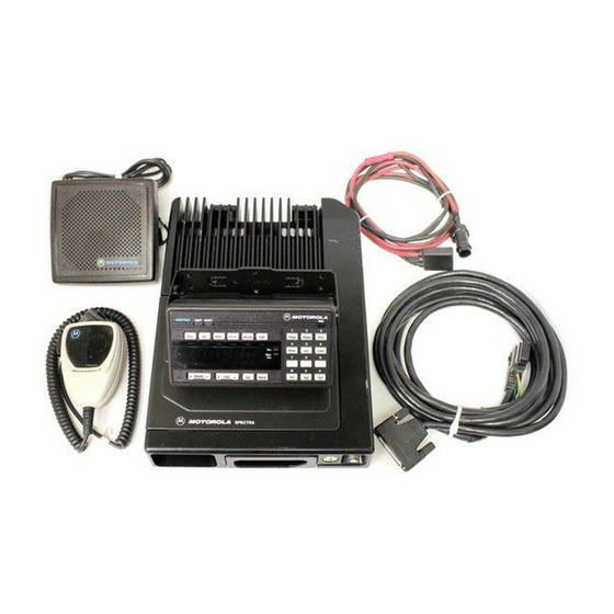
® This manual covers the installation procedures for Spectra and ASTRO Digital Spectra radios and accessories required to complete the radio system. The radio system consists of a control head, radio, antenna, microphone, speaker, cabling, and accessories. Radio Model, Control Model charts for the different versions are found in the basic service manual. -
Page 8: Radio Dimensions
Radio Dimensions The Spectra and ASTRO Spectra Radios have the following dimensions (H x W x D): 15-watt – 2.0” x 7.1” x 7.5” 20- to 35-watt and 40-watt – 2.0” x 7.1” x 8.6” Base/Control Model charts for the different versions are found in the basic service manual. -
Page 9: Figure 1 Example Of A Base/Control Station Configuration
Wall- outlet Line Cord with Ground Power Supply Outdoor Antenna Lightning Protector With Quarter Wave Shorting Stub Desktop Power Cable Speaker Desk Microphone Antenna Cable Antenna Connector Radio in Desktop Tray Figure 1 Example of a Base/Control Station Configuration... -
Page 10: Installation
The Spectra radio should operate only in negative ground electrical systems. Check the ground polarity of the vehicle before starting the radio installation making sure the polarity is correct. Accidentally reversing the polarity will not damage the radio, but will cause the cable fuses to blow. -
Page 11: Figure 2 High-Power Radio Installation (Remote) Using A4, A5, A7 Or A9 Control Heads
FUSE BATTERY RED LEAD PORT ON BACK OF CONTROL HEAD FUSE GRN LEAD FIREWALL RADIO HOLE FUSE 1 2 3 4 5 10 11 12 13 14 15 16 17 BLOCK 20 21 23 24 26 27 28 29 30 31 32 33 ORG LEAD REMOTE 34 35 36 37 38... -
Page 12: Figure 4 Low-/Mid-Power Radio Installation (Dash Mount) Using A4, A5, Or A7 Control Heads
FUSE REAR ACCESSORY CONNECTOR BATTERY RED LEAD (ASTRO SPECTRA) ANTENNA SPKR NOTE 1 VIP OUT 2 VRS TX/ NOTE 1 CTS-RS232 IGNITION SPKR SWB+ EMER FUSE FIREWALL BLOCK HOLE IGNITION CABLE DC POWER FUSE HORN CABLE ANTENNA RELAY BUS+ VIP OUT 1... -
Page 13: Figure 6 Low-/Mid-Power Radio Installation (Dash Mount) Using A3 Control Heads
FUSE BATTERY REAR ACCESSORY CONNECTOR (ASTRO SPECTRA) ANTENNA SPKR NOTE 1 VIP OUT 2 VRS TX/ IGNITION NOTE 1 CTS-RS232 SPKR FUSE SWB+ EMER FIREWALL BLOCK HOLE IGNITION CABLE LIGHT OR FUSE DC POWER HORN CABLE ANTENNA RELAY PIN-OUT CONNECTION... -
Page 14: Microphone Hang-Up Clip Installation
(Alternator whine and other noise problems may occur. Isolate the green cable with a Motorola relay, part #59-00813674.) Figure 8 Cabling Interconnect Diagram... -
Page 15: Remote Radio Control Cable Installation
Remove the fuse from the fuseholder and connect the short red cable with the fuse connection to the positive battery terminal. Cut the long red radio power cable to the proper length and strip the red insulation back 3/4" from the end. -
Page 16: Dash Mount Radio Installation
To ensure a proper water seal, the jackscrews on the radio cable connector must be tight. If the accessory port on a remote mounted radio is not used, the cover gasket assembly (HLN6233_) must be installed and torqued to 6 to C a u t i o n 8 inch-pounds. -
Page 17: Remote Mount High-Power Radio Installation
DO NOT allow water to stand in recessed areas of vertically mounted radios. Remove any moisture immediately to prevent it from seeping down into the radio. C a u t i o n For radios equipped with optional remote mount control heads, see Figure 5. -
Page 18: Remote A4, A5, A7, And A9 Model Control Head Installation
Remote A4, A5, A7, The recommended mounting surfaces for the control unit are under the dashboard, on the transmission hump, or on the center console. Figure 10 and A9 Model Control shows an example of the A4, A5, and A7 control heads. Figure 12 shows Head Installation how the bracket, control head, and cables should be installed for the A9 model control head. -
Page 19: Remote A3 Model Control Head Installation
IMPORTANT USE A METAL BACKING PLATE (NOT SUPPLIED) IF MOUNTING TRUNNION ON A PLASTIC DASHBOARD DRILL FOUR 5/32" HOLES IN DASHBOARD DASHBOARD TRUNNION 03-00136756 USE FOUR MOUNTING SCREWS ON ALL INSTALLATIONS ADJUST THE CONTROL HEAD TO DESIRED ANGLE AND SECURE WITH WING SCREWS VIP CONNECTOR ORANGE AND GREEN LEADS... -
Page 20: Transmit/Receive Control Cable Installation (A4, A5, A7, And A9 Remote Control Heads)
IMPORTANT USE A METAL BACKING PLATE (NOT SUPPLIED) IF MOUNTING TRUNNION ON A PLASTIC DASHBOARD DRILL FOUR 5/32" HOLES IN DASHBOARD DASHBOARD TRUNNION 03-00136756 USE FOUR MOUNTING SCREWS ON ALL INSTALLATIONS ADJUST THE CONTROL HEAD TO DESIRED ANGLE AND SECURE WITH WING SCREWS VIP CONNECTOR ORANGE AND GREEN LEADS... -
Page 21: Figure 13 Alternator Whine Suppressor Isolation Detail
In any application, trim and strip wires. Crimp on ring lug for battery connections. For ignition switch connections, crimp on ring or spade lug (whichever is required). Note: In cases where alternator whine or interference is a problem, isolate the green lead with a relay (Motorola Part No. 5900813674) (see Figure 13). -
Page 22: Transmitter Control Power Lead (Orange)
PLASTIC INSULATOR FUSE HOLDER MAEPF-21361-O Figure 14 Fuseholder Assembly and Parts List for Orange and Green Control Cables Parts List Fuse Assembly for Orange and Green Leads MOTOROLA DESCRIPTION PART NO. INSULATOR, Fuseholder Body 1482882A01 1482883A01 INSULATOR, Fuseholder Cap 2900136968... -
Page 23: Receiver Control Power Lead (Green)
NOTE: For mobile radios with rated power of 7 watts or less, the only installation restrictions are to use only Motorola approved antennas and install the antenna externally on metal body vehicles. For mobile radios with rated power greater than 7 Watts, always adhere to all the guidelines and restrictions in the section below. -
Page 24: Antenna Installation Procedure
BEFORE INSTALLING AN ANTENNA ON THE TRUNK LID, Be sure that the distance from the antenna location on the trunk lid will be at least 85 cm (33 inches) from the front surface of the rear seat-back to assure compliance with RF Energy Safety standards. -
Page 25: Antenna Connection
(e.g., stripping threads, deforming the collar or connector, or causing the connector to twist in the housing opening and break). Motorola recommends the following sequence to ensure proper attachment of the system (see Figure 3-10): Mini UHF... -
Page 26: Options And Accessories Installation For A4, A5, A7, And A9 Model Control Heads
INSTALL PHONE BUTTON HERE Mode Phon Scan XMIT BUSY HOME MAEPF-21423-O Figure 17 Installing the Phone Button Key on A4, A5, and A7 Model Control Heads Options and The vehicle interface port (VIP) allows the control head to operate outside circuits and to receive inputs from outside the control head. -
Page 27: Emergency Pushbutton, Footswitch, Horn Relay, And Light Relay Installation
SW B+ pin and a VIP OUT pin on the VIP Installation connector. Options and ASTRO Digital Spectra radios and Spectra radios equipped with the Accessories following features are capable of transmitting automatically, even if the radio is turned off: Installation •... -
Page 28: Mdc Emergency Pushbutton Or Footswitch Installation
All ASTRO Digital Spectra radios and Spectra radios have accessory connector pins 2 and 8 connected together to allow the radio to power down. Opening this connection by REMOVING the accessory connector, or otherwise failing to C a u t i o n maintain a normally closed path, could, if left unchecked, drain the vehicle battery, and possibly cause transmissions to occur. -
Page 29: Figure 20 Horn/Light Wiring Diagram
2. Lights Relay–Connect the relay across the headlamp ON/OFF switch, typically found in the steering column. Open the accessory cable connector and connect the two control wires (male pins) into locations 3 and 4 of the accessory connector. SPST CONNECT N.O. -
Page 30: Connecting Cables
Connecting Cables Perform the following if it has not been previously done: 1. For all models except A3, remove the control head from its mounting trunnion. Plug the radio’s control cable into the proper location on the back of the control head. (See Figures 10 and 12.) The connectors “click”... -
Page 31: Replacement Parts Ordering
Send written orders to the following addresses: Replacement Parts/ Federal Government Orders: International Orders: Test Equipment/Manuals/ Crystal Service Items: Motorola Inc. Motorola Inc. Motorola Inc. United States and Canada United States and Canada United States and Canada Accessories and Aftermarket... - Page 32 *6881070C85* *6881070C85* Motorola 8000 West Sunrise Boulevard Fort Lauderdale, Florida 33322 68P81070C85-D...
Need help?
Do you have a question about the Spectra and is the answer not in the manual?
Questions and answers