Table of Contents
Advertisement
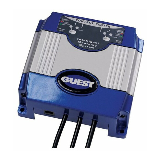
Models
16061
16102
16153
16202
IMPORTANT NOTICE
This manual contains important safety and operating instructions for the charger. Read
the entire manual before using. Also read all instructions and cautions for and on the
charger, batteries and equipment in the vicinity of the batteries.
Intelligent Charging System Series
OWNER'S MANUAL
ON BOARD BATTERY CHARGERS
Amperage
6 Amps
6,6 Amps
6,6,6 Amps
10,10 Amps
SAVE THESE INSTRUCTIONS
No. Of Banks
1 Bank
2 Banks
3 Banks
2 Banks
R
Volts
12
12 or 24
12 or 24 or 36
12 or 24
Advertisement
Table of Contents


Need help?
Do you have a question about the 16202 and is the answer not in the manual?
Questions and answers
Model 16102 bank 1 status light blinking green blue red. What does it mean
A blinking green, blue, and red status light on the Guest model 16102 indicates that the charger has reduced its output due to a DC overload or a DC short. This condition may occur because:
1. The 14-hour bulk timer has expired.
2. There is a DC overload or short.
3. On-board DC systems are drawing more current than the charger can supply.
4. Excessive ambient temperature has caused the charger to cut back output current to protect itself.
To troubleshoot:
- Load test the batteries and RED LED cells; replace if necessary.
- Remove the source of the overload or short.
- Disconnect the charger's black (negative) ring terminal from the battery, reapply AC power, and ensure only the green LED lights.
- Turn off all DC equipment while charging.
- Identify and correct the cause of excessive ambient temperature.
This answer is automatically generated