Table of Contents
Advertisement
Quick Links
User's Guide
OctaMic XTC
The Professional's Multiformat Solution
™
™
™
SteadyClock
QuickGain
AutoSet
Professional Mic/Line/Instrument Preamp
8-Channel Microphone / Line AD-Converter
4-Channel Line/Phones DA-Converter
8-Channel Analog to AES / ADAT Interface
64-Channel MADI Interface
ADAT / AES / MADI Format Converter
24 Bit / 192 kHz Digital Audio
MIDI Remote Control
USB 2.0 Class Compliant Operation
AES-3
AES-10
24 Bit Interface
Advertisement
Table of Contents

Related Manuals for RME Audio OctaMic XTC


Summary of Contents for RME Audio OctaMic XTC
- Page 1 User’s Guide OctaMic XTC The Professional’s Multiformat Solution ™ ™ ™ SteadyClock QuickGain AutoSet Professional Mic/Line/Instrument Preamp 8-Channel Microphone / Line AD-Converter 4-Channel Line/Phones DA-Converter 8-Channel Analog to AES / ADAT Interface 64-Channel MADI Interface ADAT / AES / MADI Format Converter...
-
Page 2: Table Of Contents
Digital Inputs and Outputs 13.1 AES / EBU............30 13.2 ADAT Optical ............31 13.3 MADI ..............32 Word Clock 14.1 Word Clock Input and Output.......34 14.2 Technical Description and Background ....35 14.3 Cables and Termination........36 MIDI................36 User’s Guide OctaMic XTC © RME... - Page 3 22.7 Signal to Noise ratio in DS- / QS-Operation ..55 22.8 MADI Basics ............56 22.9 SteadyClock............57 Block Diagram............58 MIDI Implementation OctaMic XTC 24.1 Basic SysEx Format ..........56 24.2 Message Types - Commands......56 24.3 Table ..............57 User’s Guide OctaMic XTC © RME...
-
Page 4: Important Safety Instructions
When mounting in a rack, leave some space between this device and others for ventilation. Unauthorized servicing/repair voids warranty. Only use accessories specified by the manufacturer. Read the manual completely. It includes all information necessary to use and operate this device. User’s Guide OctaMic XTC © RME... -
Page 5: General
User’s Guide OctaMic XTC General User’s Guide OctaMic XTC © RME... -
Page 6: Introduction
• 1 optical cable (TOSLINK), 2 m 3. Brief Description and Characteristics The OctaMic XTC is a full range hi-end preamp and AD/DA-converter in reference quality, fully remote controllable. In a standard 19" box with 1 unit height the device offers numerous ex- traordinary features like Intelligent Clock Control (ICC), SyncCheck, SteadyClock, QuickGain, AutoSet, MIDI over MADI, and remote control via USB, MADI and MIDI. -
Page 7: First Usage - Quick Start
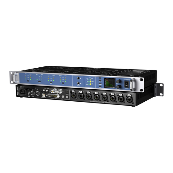
4. First Usage – Quick Start 4.1 Controls - Connectors - Displays The front of the OctaMic XTC features eight Select keys, 32 status LEDs, two stereo TRS out- puts, four menu keys, two rotary encoders with push functionality and a graphical colour dis- play. - Page 8 IEC receptacle for power connection. The specially developed, internal hi-performance switch mode power supply lets the OctaMic XTC operate in the range of 100V to 240V AC. It is short- circuit-proof, has an integrated line-filter, is fully regulated against voltage fluctuations, and sup- presses mains interference.
-
Page 9: Quick Start
4.2 Quick Start After connection of all cables and power-on of the device, the configuration of the OctaMic XTC starts in the menu SETUP – Options - Clock. Choose a clock source and a sample rate. The next step is the GAIN setting. Press the desired SELECT button and adjust the gain with the encoders, so that the two level meters do not show overload. -
Page 10: Warranty
Audio AG does not accept claims for damages of any kind, especially consequential damage. Liability is limited to the value of the OctaMic XTC. The general terms of business drawn up by Audio AG apply at all times. - Page 11 For this the device has to be sent free to the door to: IMM Elektronik GmbH Leipziger Straße 32 D-09648 Mittweida Germany Shipments not prepaid will be rejected and returned on the original sender's costs. User’s Guide OctaMic XTC © RME...
- Page 12 User’s Guide OctaMic XTC © RME...
-
Page 13: Usage And Operation
User’s Guide OctaMic XTC Usage and Operation User’s Guide OctaMic XTC © RME... -
Page 14: Front Panel Controls Select Keys
By turning encoder 2 the pages Clock, MIDI Sources, General Settings and Digital Routing are shown. The arrow under the 2 indicates that pressing encoder 2 the corresponding page is entered, and settings can be changed then. User’s Guide OctaMic XTC © RME... -
Page 15: Menu Keys
(channel number) and right (current gain). The level meter is always active for all channels. The OctaMic XTC has 8 channels, therefore no more than 4 groups with 2 channels each can be defined. The group assignment is defined in the menu CHANNEL - Gain Group. -
Page 16: Channel Menu
The displayed gain will quickly decrease to a gain that is appropriate. While AutoSet in the XTC is not exactly the same as in the RME Micstasy (with extreme overloads distortion will occur for the fraction of a second before the level is set correctly), it works quite well in real-world applications and will prevent distorted recordings reliably. - Page 17 Mute Mute of the phones output, without the need to change the current volume setting.. Phase Invert Available settings are Off, Both, Left and Right. Output Level Can be set to Low or High. User’s Guide OctaMic XTC © RME...
-
Page 18: Setup Menu
MIDI Device ID Adjustable from 0 to 7. MIDI Contr. Thru On or Off. LCD Contrast Adjustable from -20% to +20%. Default is 0%. SW-Version Shows the current version number and date of the internal software. User’s Guide OctaMic XTC © RME... - Page 19 Rec. 9-16 Choices are Mic 1-8, ADAT In, AES In, MADI In in groups of 8 channels Rec. 17-24 Choices are Mic 1-8, ADAT In, AES In, MADI In in groups of 8 channels User’s Guide OctaMic XTC © RME...
-
Page 20: Setups Menu
In the lower part of the display 5 fields, one for each MIDI input, show incoming MIDI signals. DIN ist he rear 5-pin socket, USB1/2 the according USB MIDI port (only available with an active USB connection) and MADI, which – thanks to RME’s MIDI over MADI technology - can also receive MIDI from other devices. -
Page 21: Clock
OctaMic XTC word clock output or AES/ADAT/MADI output. The OctaMic XTC thus has to be master, all devices connected to it must be slave. In order to avoid clicks and drop outs due to faulty or missing synchronicity, a special process called SyncCheck compares the incoming data and the OctaMic XTC internal clock. -
Page 22: The Input Channel In Detail Gain
9. The Input Channel in Detail 9.1 Gain The OctaMic XTC GAIN can be set in steps of 1 dB per channel. Setting the amount of amplifi- cation is done digitally, therefore being very accurate and 100% reproducable. The gain change itself is performed within the analog domain. -
Page 23: Autoset
9.3 AutoSet Some preamps include limiters in order to prevent clipping, especially of the A/D converter stage. Such a circuitry is not feasible for the OctaMic XTC, because it would spoil the mic pre- amp's excellent technical data. But as the OctaMic XTC's gain is controlled completely digitally, the device can set it automati- cally, thus providing perfect protection from overload with no degradation of the audio signal, which does not have to pass any additional electronic circuits. -
Page 24: Using Multiple Units With Madi
10. Using Multiple Units with MADI Devices like the OctaMic XTC can be connected serially via MADI, and then transmit up to 64 channels (with up to 8 XTC) over one single MADI cable. In the menu Digital Routing the user can decide at which place of the 64-channel MADI stream the current eight channels of the XTC are inserted. -
Page 25: Compensation Id
Auto-ID OctaMic XTC detects other devices sitting in front of it within the chain. If none is detected the ID is set to 1, else according to the found ID plus 1. The entry Compens. ID is grayed out, be- cause no longer manually adjustable. -
Page 26: Remote Control
96k frame mode), to transmit MIDI data invisibly within MADI, ensuring full compatibility. To remote control more than one OctaMic XTC every unit can have its own ID (menu Options - General Settings), providing a separated remote control of multiple devices via a single MIDI channel. -
Page 27: Inputs And Outputs
User’s Guide OctaMic XTC Inputs and Outputs User’s Guide OctaMic XTC © RME... -
Page 28: Analog Inputs / Outputs
12. Analog Inputs / Outputs 12.1 Mic / Line In (XLR) The OctaMic XTC has 8 balanced full range XLR inputs on the back panel. The electronic input stage is built in a servo balanced design which handles unbalanced and balanced signals cor- rectly, automatically adjusting the level reference. -
Page 29: Phones / Line Out
12.4 Phones / Line Out The OctaMic XTC has two unbalanced stereo 1/4" TRS outputs on the front. They are also spe- cial low impedance types, ready to be used with headphones. These channels are driven from a high-quality DA-converter with 118 dBA Signal to Noise ratio. Additionally two hardware-based reference levels are available. -
Page 30: Digital Inputs And Outputs
Channel Status ‘Consumer’! In such cases the above adapter cable will not work. The OctaMic XTC supports Single Wire only, in the range of 32 kHz up to 192 kHz: a total of 8 channels, 2 channels per AES wire. The effective sample frequency equals the clock on the AES wire. -
Page 31: Adat Optical
When operating with sample rates higher than 48 kHz the entry ADAT 2 in the menu Digital Routing will be grayed out. The OctaMic XTC then is in S/MUX mode, and will send the source signal selected for ADAT 1 also at the ADAT 2 port. -
Page 32: Madi
The MADI input will operate as an optional clock source (menu Clock) as well as a through in- put. Since each OctaMic XTC uses only 8 channels, up to 56 channels can be passed through, switching this function off even all 64. - Page 33 User’s Guide OctaMic XTC © RME...
-
Page 34: Word Clock
Circuit) plus SteadyClock guarantee a secure function also with most critical word clock signals. Thanks to a low impedance, but short circuit proof output, the OctaMic XTC delivers 4 Vpp to 75 Ohms. For wrong termination with 2 x 75 Ohms (37.5 Ohms), there are still 3.3 Vpp at the out- put. -
Page 35: Technical Description And Background
CD players indeed have a word clock input). Then all devices get the same clock and will work in every possible combination with each other. Remember that a digital system can only have one master! If the OctaMic XTC uses its internal clock, all other devices must be set to ‘Slave’ mode. -
Page 36: Cables And Termination
– be held at the last valid frequency. 15. MIDI The OctaMic XTC has a standard MIDI input and output, a 5-pin DIN jack each. The MIDI I/O is used for: • remote control of the OctaMic XTC, see chapter 11.1 •... -
Page 37: Class Compliant Mode
User’s Guide OctaMic XTC Class Compliant Mode User’s Guide OctaMic XTC © RME... -
Page 38: General
As Windows does not support Class Compliant mode with USB 2.0 directly, special support for the OctaMic XTC has to be installed first. This is done with the RME Driver Installer for MADI- face XT, MADIface USB and OctaMic XTC (Firmware Enabler). After that the XTC firmware update tool can update the firmware to the latest version. -
Page 39: Useful Hints
96 kHz playback and 8-channel recording. In this setup, the USB cable could even be replaced with a 10 m active one. With lower quality cables or CCK replicas, even 50 cm dock to dock to 1 m USB would be considered success... User’s Guide OctaMic XTC © RME... -
Page 40: Class Compliant Under Windows/Mac Os X
192 kHz. Alsa (Linux) does not work with USB 2 Class Compliant interfaces at this time, but it seems it can be fixed (recompiled) to do so. More information is available here: http://www.mail-archive.com/alsa-user@lists.sourceforge.net/msg28901.html User’s Guide OctaMic XTC © RME... -
Page 41: Supported Inputs And Outputs
UFX is working correctly, and the problem lies somewhere else. 20. Operation at the Unit The front panel operation in Class Compliant mode is unchanged. Only the choice of sample rate is taken over by the computer/iPad. User’s Guide OctaMic XTC © RME... - Page 42 User’s Guide OctaMic XTC © RME...
-
Page 43: Technical Reference
User’s Guide OctaMic XTC Technical Reference User’s Guide OctaMic XTC © RME... -
Page 44: Technical Specifications
• Channel separation: > 110 dB • Output: 6.3 mm TRS stereo jack, unbalanced • Maximum output level at 0 dBFS, High: +17 dBu • Maximum output level at 0 dBFS, Low: +2 dBV • Output impedance: 30 Ohm User’s Guide OctaMic XTC © RME... -
Page 45: Digital Inputs
• Quad Wire: up to 16 channels 24 bit 192 kHz • Lock range: 28 kHz – 54 kHz • Jitter when synced to input signal: < 1 ns • Jitter suppression: > 30 dB (2.4 kHz) User’s Guide OctaMic XTC © RME... -
Page 46: Digital Outputs
• Supported sample rates: 28 kHz up to 200 kHz 21.5 MIDI • 16 channels MIDI • 5-pin DIN jacks • Optocoupled, ground-free input MIDI over MADI • Invisible transmission via User bit of channel 56 (48k frame) User’s Guide OctaMic XTC © RME... -
Page 47: General
• Temperature range: +5° up to +50° Celsius (41° F up to 122°F) • Relative humidity: < 75%, non condensing 21.7 Firmware The OctaMic XTC is internally based on programmable logic. By re-programming of a little component called Flash-PROM, both function and behaviour of the unit can be changed at any time. -
Page 48: Connector Pinouts
3/4- 5/6+ 5/6- 7/8+ 7/8- D-Sub Signal 1/2+ 1/2- 3/4+ 3/4- 5/6+ 5/6- 7/8+ 7/8- D-Sub GND is connected to pins 3, 6, 9, 12, 14, 17, 20, 23. Pin 1 is not connected. User’s Guide OctaMic XTC © RME... - Page 49 RCA phono plugs, or TRS plug to TS plugs is required. The pin assignment follows international standards. The left channel is connected to the tip, the right channel to the ring of the TRS jack/plug. User’s Guide OctaMic XTC © RME...
-
Page 50: Technical Background
The Quad Wire method allows to transmit two channels at up to 192 kHz via ADAT. The method is referred to as S/MUX4. Note: All conversions of the described methods are lossless. The existing samples are just spread or re-united between the channels. User’s Guide OctaMic XTC © RME... -
Page 51: Lock And Synccheck
PLL tracks the receiver's frequency. If an AES or MADI signal is applied to the OctaMic XTC, the corresponding LED starts flashing. The unit indicates LOCK, i. e. a valid input signal (in case the signal is in sync, the LED is con- stantly lit, see below). -
Page 52: Latency And Monitoring
Noise ratio, lowest distortion figures and lightning quick conversion. A delay of only 10 sam- ples hasn’t been available just a few years back. But even the chip used for DA-conversion has a lower delay than usual. The exact delays caused by the AD-conversion of the OctaMic XTC are: Sample frequency kHz 44.1... -
Page 53: Ds - Double Speed
(CD...), Quad Speed has had no broad success so far. An implementation of the ADAT format as double S/MUX (S/MUX4) results in only two channels per optical output. Therefore in Quad Speed mode the OctaMic XTC is limited to 4 channels at the ADAT outputs. -
Page 54: Aes/Ebu - Spdif
The table shows that a Professional-coded signal would lead to malfunctions for copy prohibi- tion and emphasis, if being read as Consumer-coded data. Nowadays many devices with SPDIF input can handle Professional subcode. Devices with AES3 input almost always accept Consumer SPDIF (passive cable adapter required). User’s Guide OctaMic XTC © RME... -
Page 55: Signal To Noise Ratio In Ds- / Qs-Operation
22.7 Signal to Noise Ratio in DS- / QS-Operation The outstanding signal to noise ratio of the OctaMic XTC's AD-converters can be verified even without expensive test equipment, by using record level meters of various software. But when activating the DS and QS mode, the displayed noise level will rise from -113 dBFS to -106 dBFS at 96 kHz, and –79 dBFS at 192 kHz. -
Page 56: Madi Basics
64 channel format, but offer still no more than 56 audio channels. The rest is being eaten up by control commands for mixer settings etc.. The OctaMic XTC shows that this can be done in a much better way, with an invisible transmission of 16 MIDI channels plus serial RS232 data stream, and the 64-channel MADI signal still being 100% compatible. -
Page 57: Steadyclock
Latest circuit designs like hi-speed digital synthesizer, digital PLL, 100 MHz sample rate and analog filtering allow RME to realize a completely newly developed clock technology, right within the FPGA at lowest costs. The clock's performance exceeds even professional expectations. -
Page 58: Block Diagram
23. Block Diagram User’s Guide OctaMic XTC © RME... -
Page 59: Basic Sysex Format
00 20 0 69 00 20 01 1c 08 7f 0a 30 10 0d f7 Set Gain Mic 2 to 37dB; Pad on; Phase-Invert, Mute, AutoSet, 48V off; all parameters to be set. Set Phones 1 source to MADI1/2; high Level, Phase-Invert off, Mute not to be set. User’s Guide OctaMic XTC © RME... -
Page 60: Table
Bit 0-1: Delay Compensation (0-Off, 1-Manual, 2-Auto-ID, 3-Auto CA) 0x01 Bit 2: MADI-Format (0: 56ch, 1: 64ch) 0x02 Bit 3: MADI-Frame (0: 96k, 1: 48k) 0x04 Bit 0-2: Delay Compensation ID (0-7 for ID 1-8) 0x08 User’s Guide OctaMic XTC © RME... - Page 61 Bit 2-3: Phase Invert (0: off, 1: both, 2: left, 3: right) 0x04 Bit 4: Level (0: Low, 1: High) 0x08 Digital Routing Bit 0-3: Source 1 (see Value Table 2) 0x01 Bit 0-3: Source 2 (see Value Table 2) 0x02 User’s Guide OctaMic XTC © RME...
- Page 62 M 9-16 M 17-24 M 25-32 M 33-40 M 41-48 M 49-56 M 57-64 PB 1-8 PB 5-12 PB 9-16 PB13-20 PB17-24 Value Table 3 – MIDI Sources MADI USB1 USB2 DIN in Control User’s Guide OctaMic XTC © RME...
Need help?
Do you have a question about the OctaMic XTC and is the answer not in the manual?
Questions and answers