
Related Manuals for Rehau Ba


Summary of Contents for Rehau Ba
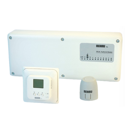
- Page 1 Ba heating/cooling controlS technical & inStallation manUal Building Solutions www.rehau.co.uk Automotive Industry...
-
Page 2: Table Of Contents
2.4.2 ..Installation ....... . 21 3.0 ..REHAU Intelligent Heating/Cooling Control Systems ....22 3.1 . - Page 3 8.1 ..Setting the Sensor Channel Number ..... . 42 8.2 ..REHAU BA Master Controller ......43...
- Page 4 9.0 ..Commissioning ......44 9.1 ..Pre-commissioning Requirements ..... . 44 9.2 .
- Page 5 If a floor heating system is added to an existing heating or hot water system, containing mild steel pipes, a strainer must be fitted straight after the branch off. All REHAU control systems must be installed. - By a competent person...
-
Page 6: Principles Of Underfloor Heating/Cooling
Energy-saving thermal vortex is formed. Dust circulation and the Due to the REHAU underfloor heating systems’ high carbonising of dust are thus a thing of the past. proportion of radiant energy, comfort conditions can... -
Page 7: Principle Of Ufc
Cooling capacity body occurs via main three 4. Air temperatures and air speeds with pipe underfloor cooling standard cooling capacity mechanisms: of the REHAU underfloor cooling - Radiation system is 50W/m in accordance Influencing factors on the cooling capacity - Evaporation with DIN 4715-1. -
Page 8: Fixed Flow Water Temperature (Fft) System
For domestic and smaller commercial applications requiring a mixing the boiler flow with cooler water from the return of the floor constant temperature system, REHAU offers a small and compact heating circuits. Once flow set point is achieved the mixing valve mixing unit called the compact mixer unit. -
Page 9: Zone Control
UFH - Manifold UFH - Return 5. Individual zone control with FH The REHAU INTELLIGENT zone control system is a simple electronic In cooling mode: control system that has been specifically designed to The cooling output in each room is controlled by a room sensor give optimum and accurate control of Floor Heating systems. -
Page 10: Fixed Flow Temperature Control
Constant Temperature Thermostatic Mixing Component REHAU Art. No. Compact Mixer Unit Valve Configuration Compact Mixer Unit 237092 ½" Balancing Valve (BV) + ½" TIV (for outputs up to 12kW) 237102 1x¹... -
Page 11: Fixed Temperature Mixing Options
FIxEd Flow tEMPERAtURE contRol FIxEd tEMPERAtURE MIxIng oPtIonS 2.2.1 Compact Mixer Unit - Only for domestic/light commercial applications - For outputs up to 12kW use 1/2" valve set (not to be used to size primary pipes) - For outputs between 12 - 18kW use 3/4" valve set (not to be used to size primary pipes) - The circulating pump only circulates the warm water through the circuits. -
Page 12: Installation
Thermostatic Mixing Valve Boiler Lock Shield Valve Thermostatic Radiator Valve 9. Hydraulic layout of REHAU Compact Mixer Unit with ‘S’ plan Integration 2.2.3 Installation - If a module needs to be mounted onto the left side of the manifold: Supplied... -
Page 13: Thermostatic Mixing Valve (Tmv)
FIxEd Flow tEMPERAtURE contRol FIxEd tEMPERAtURE MIxIng oPtIonS 2.2.3a Before the system is switched on, the following settings 2.2.4 Thermostatic Mixing Valve (TMV) have to be carried out: - Suitable for all applications, below 30Kw. Above this weather - Balancing valve (BV) set to fully open as per recommendations on compensation is recommended the instruction leaflet supplied with the compact mixer - Use the correct size of mixing valve (according to required heat... -
Page 14: Installation
TMV and the pump outlet to the flow header of the floor heating manifold. CT2/ HW BA Master Controller Junction Box CT2/ R Hot Water Supply... - Page 15 FIxEd Flow tEMPERAtURE contRol FIxEd tEMPERAtURE MIxIng oPtIonS Data Thermostatic Mixing Valves (Fixed Flow 3-Port) For up to 15kW: Dimensions : 130mm x 95mm x 43mm (H x W x D) Outlet temperature setting : 35ºC to 65ºC Hot water supply : max 90ºC Temperature stability 9 nominal : ±...
-
Page 16: Required Components For Zone Control
REHAU TP (Tamper resistant sensor) 225109-001 Up to 8 zones: maximum of 7x Up to 14 zones: maximum of 13x REHAU TA (Standard Sensor) 225106-001 REHAU TD (Comfort plus sensor, includes floor sensor) 225116-001 REHAU TM (Comfort sensor) 225107-002 REHAU HS (Humidity sensor) 229435-001... -
Page 17: Wiring
EXT. 230VAC 230VAC SWITCH SENSOR LINK SUPPLY BOILER X-Relay SEC. PUMP 230VAC B1 B2 VOLT FREE 230VAC UFH Circulation Pump Brown Compact mixer Blue connection block Green & Yellow 12. Compact Mixer Wiring Compact Mixer Wiring to the BA Controller... - Page 18 GREEN/YELLOW equipment should be used for correct wiring. The above wiring diagram is for guidance only and should not be used as a definitive wiring diagram 14. Connecting for separate high limitation to the BA Master Controller...
- Page 19 230V Boiler output signal The connections are volt free. Do not apply a voltage to the Potential free EXT SWITCH as this will damage the unit. boiler output BOILER signal Remote start terminal of boiler 15. Intergrating BMS with REHAU Intelligent Controls...
-
Page 20: Temperature Safety Options
16. Recommended Position of HLS (3-Port) valve 2.3.3 Dew Point Control The dew point control of the system is performed by the BA Master Controller coupled with the Humidity sensors positioned within the index rooms (refer section 4.2). The controller will calculate the dew point temperature based on the index room temperature and the % of relative humidity within the index room. -
Page 21: 2-Port Zone Valve (Zv)
FIxEd Flow tEMPERAtURE contRol 2-PoRt ZonE vAlvE (Zv) 2.4.1 Working Principle The 2-Port zone valve (ZV) has a dual function: - To separate the fl oor heating system hydraulically from other systems supplied by the same heat source, such as the domestic hot water system (DHWS) or radiators - Close down the fl ow of hot water from the boiler in case of a boiler malfunctioning. -
Page 22: Installation
Supplied - The valve should be installed without blocking any vent or cold feed Required Components by REHAU when closed 2-Port Zone Valve of correct size - Positioning the zone valve (ZV) at an angle is possible, but it must... -
Page 23: Rehau Intelligent Heating/Cooling Control Systems
225113-002 (24V) The REHAU BA Master Controller is suitable for connecting up to 8 zones of multiple sensors and 24V actuators. In addition it provides outputs for the FH secondary pump, main pump and boiler demand signal. Add On, Module 225115-002 The Add On Module provides another 6 zone connections. - Page 24 (5V) required. This includes 2 connector blocks each with 2 small cables with RJ 45 connectors. REHAU CT2 / HW, Hot Water Controller 202234-001 This 24/7 clock combined with the 4-event timer enables the user to customize his domestic hot water (5V) according to his requirements.
-
Page 25: Components Overview Heating/Cooling
BA Cooling Kit 202233-001 The BA Cooling Kit contains a humidity sensor, WLAC switch and a fl ow temperature sensor. This kit when (5V) integrated into the system helps prevent the fl ow of water temperature below the dew point ( in cooling mode) and there by prevent condensation. - Page 26 Zone of Radiators that are hydraulically independent from an underfl oor heating system. For more information refer to section 11.2, see page 55. REHAU RF CT2 / 2, Two Stage Controller 202229-001 This wireless 24/7 clock combined with the 4-event timer enables the user to customize his room (5V) temperature according to his requirements.
-
Page 27: Working Principle
REHAU PI control eliminates the ‘hunting’ behaviour BA for fi xed fl ow water temperature. The master control units will then control the operation of circuit actuators, main system pump, and can help to increase the cycle life of all system components. -
Page 28: Required Components For Zone Control
20°C by 8am. 8°C As the REHAU intelligent master uses a software algorithm to control the time to warm up, this varies the required start up point by learning from its previous sensor history and only switching on... -
Page 29: Control System First Fix
Maximum cable length from BA to Add On Module 100m connection of the sensors and the BA controller, Care must be taken to ensure Maximum distance of flow temperature sensor to controller correct wiring connection between sensors & controller terminals if wires of the... -
Page 30: Positioning The Ba Master Controller Room Sensors And Remote Air/Floor Sensors
2. The sensor must not be positioned in draughts, above a heat source or where the temperature will be influenced by localised Unlike the REHAU TD floor sensor the remote air sensor is only heat gains from direct sunlight, water pipes or appliances. -
Page 31: Control System Second Fix
Green: Main boiler (primary) pump is running (if installed) Green: Power supply connected, Red: Night setback is running, Red flashing: Indicates error The REHAU BA control unit can operate 8 heating zones, each of which may have a number of floor heating circuit actuators connected. -
Page 32: Electrical Connection
E in the Boiler relay will energise 60 seconds after the start of main pump. controller. (As shown in Fig. 23). On the REHAU BA Master Controller, the boiler demand will stop if there is no demand from a room sensor. -
Page 33: Pump Outputs - Ufh Pump
DIP SWITCHES DIP SWITCHES BA controller has a relay which can be utilized for a number of different purposes. The relay is a volt free output and is positioned on the PCB 1 2 3 4 5 6 7 8... -
Page 34: Connecting Rehau Add On, Extension Modules
0.3m apart from the Master Controller) 25. Connecting extension modules 26. X - Output on the BA controller The addition of REHAU Add On Extension module will increase X - Output the zoning potential from 8 to 14 zones. The Master Controller... -
Page 35: Connecting Room Sensors
- The maximum system cable length using a daisy chain layout is 300 mtr, with a maximum cable length between sensors of 100 mtr. - The maximum distance a sensor can be from the REHAU BA Master Controller is 100 mtr. when connected in star configuration. (Refer to Fig.27) -
Page 36: Connecting Thermal Actuators (Th 1 - Th 8)
REHAU CT2 Programmable respective zone output terminal block (TH 1-TH 6) then connect the Room Sensor. No system programming is available with the REHAU BA other wire from the actuator to the left hand terminal block. These controller. -
Page 37: Room Sensors Internal Connections
5.3.1a Connecting the Remote Air Sensor components on the printed circuit board at this point. The sensor is connected to the REHAU TM sensor as shown in Fig. 32a. When the sensor is fitted the REHAU TM sensor function will Care should also be taken not to deform the sensor back plate operate in the same way. -
Page 38: Floor Sensor Option (Td Sensor Only)
If connected to a system fitted with a REHAU BA Master Controller these hand side of the printed circuit board controlling the minimum or limits can be adjusted using the BA menu. Adjusting the limits this way will maximum temperature. The temperature limits are adjustable within control either the min/max temperatures for all floor sensors within the group. -
Page 39: Wireless Sensors/Controllers Set Up
6.1.1 Set up mode button Where wireless Room sensors/controllers are being used, it is Channel necessary for the BA Master Controller to confi rm that the Room selector Sensors/Controllers are communicating correctly. RF CT2 Programmable Room Sensor/Controller To achieve this: 1. -
Page 40: Technical Data
REHAU BA Master Controller REHAU Wireless Receiver (RC) 36. Connection of Master And Wireless Receiver 6.1.2 Technical Data Connection of master and receiver The receiver is connected to the master or the add on module using the included cable. Max distance between the master/add on module... -
Page 41: Setting Up Ba Master Controller (Cooling)
SEttIng UP BA MAStER contRollER (coolIng) The REHAU BA Master Controller is an independent floor heating / cooling control system. It requires manual switching of the system from heating to cooling and back to heating using a WLAC switch or a volt free signal from the BMS. Thus, being able to give an output demand signal to boiler, chiller or a reversible heat pump. -
Page 42: Using Dehumidifier
7.6 Dew Point Control If cooling is being limited due to high humidity a dehumidifier can The dew point control of the system is performed by the BA Master be enabled by the BA Master Controller. The dehumidifier can be... -
Page 43: System Start Up And Operating Instructions
However when the power is on the sensors will need to be given control designation (see section 8.0) and a HARD RESET must be carried out to the REHAU BA 39. REHAU CT2 Programmable Room Sensor front cover layout controller to enable all sensors to be recognised. -
Page 44: Rehau Ba Master Controller
If a REHAU CT2 Clock Thermostat is NOT fitted on the system an external time clock will be required However if a REHAU CT2 Clock sensor is fitted to the system it will to control the time switching of the system. -
Page 45: Commissioning
- Confirm correct operation of the system controls including the sequencing of the pumps and boiler. For fixed flow water temperature control (REHAU BA Master Controller) follow the steps in the Underfloor Heating Systems - Installation Guide 890.605E section Initial system warm up. This details the start up temperature to the FH. -
Page 46: Ct Set Up Guide
Reset to Pin button factory setting adjust of clock 42. REHAU CT2 Programmable Room Sensor/Controller front cover layout The REHAU CT2 Programmable Room Sensor Controller has 3 main buttons to navigate: UP , DOWN and ENTER (circled). 0:00 0:00 Automatic mode... - Page 47 The time will have to be set as soon as the CT2 Programmable Room Sensor is switched on for the first time, the hour digits start to flash. 1.1a To change the hours on the clock, use the to select the correct hour (24 hour clock is default) and then press I I:00 I I:00...
- Page 48 24hr/°C N.B. All event times must be in the same 24hr period. REHAU recommend a 2 hour warm up / cool down time for your underfloor heating, e.g. to be warm at 7am, start the first event, DAY, at 5am.
- Page 49 2.1a Hold the button for 3 seconds. This screen will be displayed. This shows the start time of the first event, DAY, which is the first time the heating comes on. If this is to be changed, use the UP and DOWN arrows like when setting the time. If it is not to be changed, press twice to move on.
- Page 50 2.6a Days 6 and 7 (Saturday and Sunday) only have 2 events - DAY and NIGHT. This screen shows the start time of day event. Adjust if required as above. If not press twice to continue. 2.6b The temperature for DAY event at weekend. Adjust if required as above.
- Page 51 changing event sequence over different days (if required) Hold UP and DOWN buttons to reach sub-menus. Scroll through and press on Pro. The 5 possible sequences below can be scrolled through and selected by 4.1a 4 events on 5 days, 2 events on 2 days (default). 4.1b 4 events on 6 days, 2 events on 1 day.
- Page 52 5.1 Adjust maximum floor sensor temperature with UP and DOWN buttons, press to confirm. N.B. Only a maximum OR minimum floor sensor can be fitted to each CT2 Programmable Room Sensor, not both. 5.2 Select LoLi if minimum floor sensor fitted. 5.3 Adjust minimum floor sensor temperature as above.
- Page 53 7.1 Press UP and DOWN to scroll through options and to select desired scale. The first is 24 hour clock and temperature in celsius. 24 hour clock and temperature in fahrenheit. 7.3 12 hour clock and temperature in celsius. 7.4 12 hour clock and temperature in fahrenheit. Turning on Adaptive function ensures that the room will reach the correct temperature at the desired time.
- Page 54 Below only required for CT2 / 2 Controller (Two Stage Controller) To change advanced settings on the two stage controller Advanced settings on two stage controller. Using these settings, the secondary heat source could be turned on if the room does not reach the correct temperature in the desired time. An example would be to bring the second stage if temperature has not reached 2°C of the set point within 30 minutes Hold UP and DOWN buttons to reach sub-menus.
-
Page 55: Domestic Hot Water (Dhw), Radiators And Two Stage Controller
NOT USED Mains ZONE VALVE ON DHW CIRCUIT fall below the set temperature Supply Orange 46. Wiring Schematic for REHAU CT2/HW Hot Water Controller and 24V Zone Valve Channel Selector Brown Set to Output 5 Grey Blue * This may be reduced to a lower setting if solar generation of hot water is employed, so Green/ Yellow that best use is made of the “free”... -
Page 56: Radiators
REHAU CT2/R Controller LINK If thermostatic radiator valves are employed, these can be used for individual room control, and the REHAU CT2/R can be used as a timing 24 V RELAY THERMAL ACTUATORS 24V SENSOR BUS MIXING VALVE 24V AC EXT. -
Page 57: Two Stage Room Temperature Controller
When a timed event occurs to raise the room temperature a function within the controller allows the normal heating system to initially try to The Two Stage Controller is installed as part of the BA achieve the temperature. If after a period of time (x) it has not warmed controller and set to a channel number, e.g. -
Page 58: Special Functions
1 slave to string 2 submaster or string 1 slave to string 2 slave as shown in Fig.50. 4. An BA Master Controller can be used as the “network controlling master” for central mixing control of supply water and... -
Page 59: Dip Switches
12.0 SPEcIAl FUnctIonS 12.2 dIP SwItcHES DIP Switch Function Description DIP switches (located on the master controller) Turn on to activate install mode Increase temperature on sensor in room 1, this would activate actuator on output 1 and will open after 1-3 minutes, UFH pump to turn on and mixing valve 1 2 3 4 5 6 7 8 to open;... -
Page 60: Holiday Override Function
Permanent Override CT2 Programmable Room Sensor set to Channel 0 can be used for REHAU CT2 clock sensors controlling a group of slave sensors but If the system if fitted with REHAU CT2 Programmable Room do not control actuators. The position of these sensors should be... -
Page 61: Checking Control System Operation
12.0 SPEcIAl FUnctIonS 12.4 cHEckIng contRol SYStEM oPERAtIon After setting the channels, it is possible to check the entire control system. Area circled shows the DIP switches on the Master Controller System check procedure 1. Sensor check: a. Switch on DIP-3 to activate sensor check - power light starts blinking. b. -
Page 62: Troubleshooting And Error/Fault Messages
Pump may be faulty. Output relay for Main pump, Cooling, Incorrect connection to device (output relay has volt free contacts, see BA Master Controller wiring diagram for correct connection). High limit valve or other attached Bad electrical connection between terminals and attached device. - Page 63 Supply Limit sensor may be subject to heat migration. Upstream water temperature is excessively high (these problems may be corrected by changing PI settings – please refer to the REHAU Intelligent BA Heating/Cooling Controls, Technical and Installation Manual). Room is too cold.
- Page 64 No connection to wireless receiver REHAU RC. 11 Flashes Step 2 on 2-step controller REHAU CT2/2 is used by another Room Sensor/ Controller. Only one error/fault condition can be shown at a time. If more than one error occurs, they will be prioritised in the sequence of flashes.
-
Page 65: Voltage Measurements
The limit sensor on the CT2 Programmable Room Sensor/Controller is defective. Replace the faulty sensor. Reset is NOT required. 4 Flashes Defective REHAU CT2 Programmable Room Sensors/Controllers. If a CT2 Programmable Room Controller operating a group of Room Sensors becomes defective, the remaining Room Sensors will continue control within the maximum and minimum limits programmed into the Master Controller. -
Page 66: Resets
Room Sensors/ Controllers that are functioning correctly. * Hard resets do not alter the temperature settings already programmed into the BA Master Controller. 14.1 Replacing Faulty Sensor/ Controller 1. Identify the sensor/controller to be changed by the blinking 6. -
Page 67: Sensor Failure/Actuator And Pump Exercise
15.0 SEnSoR FAIlURE/ActUAtoR And PUMP ExERcISE 15.1 Sensors/Controller Failure If a Room sensor/controller is defective or if the communication to the unit is interrupted, an alarm will be triggered. Depending on the system configuration the control will continue in one of the following ways. -
Page 68: Wiring Schematic - Next Generation
TURN ON DIP 7 FOR DEHUMIDIFIER (COOLING ONLY) NUMBER (1-F) must be used to connect the Add On Modules to the BA Increase temperature on sensor in room 1, this If a dehumidifier is being used it can be connected via... - Page 69 Working conditions and use under conditions for which the product was not intended and over which we have no influence exclude any claim resulting from our information. We recommend that a suitable check is made as to whether the REHAU product is suitable for the envisaged purpose. Application, use and processing of the products is carried out beyond the scope of our control and are therefore carried out exclusively at your own responsibility.
Need help?
Do you have a question about the Ba and is the answer not in the manual?
Questions and answers