
Related Manuals for ComfortNET CTK01


Summary of Contents for ComfortNET CTK01
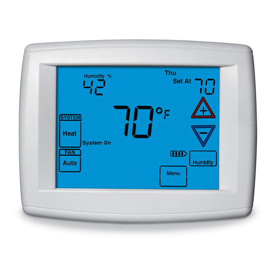
- Page 1 Installation and Start-Up Instructions An Exclusive Touchscreen Control Featuring Serial Communication Model CTK01...
-
Page 2: Introduction
FAILURE TO READ AND FOLLOW ALL INSTRUCTIONS CAREFULLY BEFORE INSTALLING OR OPERATING THIS CONTROL AND SYSTEM COULD CAUSE PERSONAL INJURY AND/OR PROPERTY DAMAGE. CAUTION WARNING To prevent electrical shock and/or equipment Thermostat installation and all components damage, disconnect electric power to system of the control system shall conform to Class II at main fuse or circuit breaker box until instal- circuits per the NEC code. -
Page 3: Table Of Contents
Table of Contents Introduction ....... . Inside Front Cover Installation ..........4 Thermostat Kit Contents . -
Page 4: Installation
Installation instructions for the furnace or air handler and outdoor AC condensing unit or heat pump are provided with each of these devices. WARNING This thermostat is designed exclusively for Amana/Goodman brand ComfortNET System equipment ONLY. This thermostat can ONLY be used with compatible Amana ®... -
Page 5: Battery Location
nstallatIon A communicating furnace matched with a communicating outdoor AC condensing unit A communicating furnace matched with a communicating outdoor heat pump unit A communicating furnace matched with a non-communicating, single stage AC condensing unit System configurations other than those noted above will not function or may function properly at greatly reduced performance. -
Page 6: Thermostat Installation Location
nstallatIon ontrol nStallation oCation Locate the control on a vibration-free inside wall in an area having good air circulation. The control should be located approximately five feet high. The control should be located in an area such that it is not influenced by the following: ... -
Page 7: Quick Installation Steps
nstallatIon Alternate indoor unit to outdoor unit wiring: In some installations, only two wires may be available for low voltage control wiring at the outdoor unit. If this is the case, use the existing low voltage control wires and connect the 1, and 2 terminals as shown in the figure below. -
Page 8: Installing The Thermostat
nstallatIon uiCK nStallation tePS Determine location of thermostat installation. Mount thermostat base to wall. Connect wires to thermostat base. Remove battery tag to provide battery power to the thermostat. Attach thermostat to base. Turn on power to system. ... -
Page 9: Initial Power Up
nItIal ower oWer Turn on AC power to the system. The thermostat will automatically search for and identify the digitally communicating components installed. While searching for system components, the thermostat will scroll the word hermoStat eSSageS “SEARCHING” in the message area to indicate that the system is looking for components (Air Handler, Furnace, Heat Pump, Air Conditioner) on the Climate... -
Page 10: Check System Operation
nItIal ower heCK yStem Peration Fan Operation Turn power on to the system. Press Run Schedule. Press FAN until FAN On is displayed. The fan should begin to operate. Press FAN until FAN Auto is displayed. The fan should stop operating. Heating System ... -
Page 11: Thermostat Set-Up
herMostat urrent ime anD On Home Screen Display, touch the Menu key to display additional key choices. Touch Set Time once to display hour and AM or PM designation in clock display. Touch either the key until you reach the correct hour and AM or PM designation. Then touch Set Time again to display min- utes only in clock display. -
Page 12: Choose The System Setting
herMostat , Emer, Auto) hooSe the yStem etting Touch the SYSTEM key to select: Heat: Thermostat controls only the heating system. Off: Heating and Cooling systems are off. Cool: Thermostat controls only the cooling system. Em: Emergency setting available only when the thermostat detects a heat pump in the system Auto: Auto Changeover is used where both... -
Page 13: Thermostat Set-Up Options
herMostat hermoStat PtionS The Thermostat has options that can be selected and adjusted. These options are in the Thermostat Options Configuration Menu. To enter the menu from the Home Screen Dis- play, touch the Menu key to display additional key choices. Touch and hold for 3 seconds the Installer Config key. - Page 14 herMostat Select Continuous FAN speed. Default fan speed is Medium. The fan speed can be set to High, Medium or Low. In High, the fan will run at 70% of the highest fan speed. In Medium, the fan speed will be 50% of the highest fan speed.
- Page 15 herMostat Select continuous backlight. Scrolling message will show “BACKLIGHT”. When bL is selected On the backlight will be on continuously. Selecting bL OFF will allow the backlight to turn on momentarily when any key is touched. If thermostat is operating with battery power only, and bL is On, the backlight will turn on momentarily.
- Page 16 herMostat Select beeper (audio prompt) Default is On for the beeper to indicate a touch key touch. It can be changed to OFF. Select air filter maintenance reminder. Scrolling message will show “AIR FILTER MAINTENANCE”. Default is OFF. It can be changed to a setting from 25 to 1975 hours in increments of 25 hours to select the amount of time for the reminder.
- Page 17 sIng the herMostat hooSe the yStem etting Touch the SYSTEM key to select: Heat: Thermostat controls only the heating system. Off: Heating and Cooling systems are off. Cool: Thermostat controls only the cooling system. Em: Setting is available only when the system is a heat pump.
-
Page 18: Using The Thermostat
sIng the herMostat emPorary rogram VerriDe This feature will override the program temperature setting until the next program period begins. Touch keys to adjust the temperature. The display will indicate “Temporary Hold At” to the left of the set-point temperature. To cancel the temporary setting before the next period begins, touch Run Schedule to return to the program. - Page 19 sIng the herMostat fan S hooSe the etting uto or FAN Auto is the most commonly selected setting and runs the fan automatically when the heating or cooling system is on during a program period. Fan On selection runs the fan continuously for increased air circulation or to allow additional air cleaning.
-
Page 20: Advanced Installer Configuration Menu
dvanced nstaller onfIguratIon The Advanced Installer Configuration Menu provides access to system configuration options, diagnostics, and identification information. ntering anD aVigating the DVanCeD nStaller onfiguration erViCe nformation On the Home Screen Display, touch the Menu key to display additional key choices. Touch and hold the Installer Config key for approximately 3 seconds to enter the Thermostat Options Configuration. -
Page 21: Equipment User Menus
dvanced nstaller onfIguratIon QuiPment enuS The equipment found in the system will display in the scrolling message area. Touch to step through the list of equipment connected, including thermostat. To view the Equipment Menus information for the equipment displayed in the scrolling message area, touch Installer Config to enter that equipment sub-menu listing. - Page 22 dvanced nstaller onfIguratIon Touch to step through the items of the equipment sub-menu and view settings. If a setting can be adjusted, the keys will appear. Change the setting as required. Touch to step to the next item. “WORKING” will appear and then the display will show “DONE”...
- Page 23 dvanced nstaller onfIguratIon QuiPment enuS Each Equipment User Menu has sub-menus to divide the information into categories. Each piece of equipment has a different set of sub-menus, with different parameters depending on the equipment. The sub-menus are showing the similar information for each piece of equipment.
-
Page 24: Thermostat User Menus
dvanced nstaller onfIguratIon hermoStat enuS Sub-menu Item User Modifiable Options Comments Outdoor ON = OD Temp is displayed Temperature Display continuously (od TEMP) bL = Alternates OD temp and time OFF = Time is displayed continuously Resistance Heat From heat pump disable Available only for air handler + heat Disable Temperature temperature to 95˚F in 5˚F... -
Page 25: Furnace User Menus
dvanced nstaller onfIguratIon urnaCe enuS onfiguration Sub-menu Item Indication (for Display Only; not User Modifiable) Number of Heat Displays the number of furnace heating stages Stages (HT STG) Input Rate (BTU/HR) Displays the furnace input rate in kBtu/hr Motor HP (1/2, 3/4 Displays the furnace indoor blower motor horse power or 1 MTR HP) iagnoStiCS... - Page 26 dvanced nstaller onfIguratIon DentifiCation Sub-menu Item Indication (for Display Only; not User Modifiable) Model Number Displays the furnace model number (MOD NUM) Serial Number Displays the furnace serial number (Optional) (SER NUM) Software Displays application software revision (SOFTWARE) Sub-menu Item User Modifiable Options Comments Heat Airflow Trim...
-
Page 27: Air Handler User Menus
dvanced nstaller onfIguratIon tatuS Sub-menu Item Indication (for Display Only; not User Modifiable) Mode (MODE) Displays the current furnace operating mode CFM (CFM) Displays the airflow for the current operating mode PPlieS only to a CommuniCating furnaCe matCheD With a aC) (S CommuniCating aliD... -
Page 28: Diagnostics
dvanced nstaller onfIguratIon iagnoStiCS Sub-menu Item Indication/User Comments Modifiable Options Fault 1 (FAULT #1) Most recent air handler fault For display only Fault 2 (FAULT #2) Next most recent For display only air handler fault Fault 3 (FAULT #3) Next most recent For display only air handler fault Fault 4 (FAULT #4) - Page 29 dvanced nstaller onfIguratIon Sub-menu Item User Modifiable Options Comments Heat Airflow Trim -10% to +10% in 2% Incre- Trims the electric heating airflow (HT TRM) ments by the selected amount. tatuS Sub-menu Item Indication (for Display Only; not User Modifiable) Mode (MODE) Displays the current air handler operating mode CFM (CFM)
-
Page 30: Air Conditioner And Heat Pump User Menus
dvanced nstaller onfIguratIon onDitioner enuS onfiguration Sub-menu Item Indication (for Display Only; not User Modifiable) Number of AC Stages Displays the number of air conditioning stages; applies to AC (CL STG) and HP. Number of HP Stages Displays the number of heat pump stages; applies to HP only. (HT STG) AC Tonnage (TONS) Displays the air conditioning tonnage;... - Page 31 dvanced nstaller onfIguratIon enSorS Sub-menu Item Indication/User Comments Modifiable Options Outdoor Air Displays the outdoor Sensor may or may not be available Temperature air temperature on an air conditioner. Check air (AIR TMP) conditioner instructions for details. Outdoor Coil Tem- Displays the outdoor Required for heat pump operation.
- Page 32 dvanced nstaller onfIguratIon Status Sub-menu Item Indication (for Display Only; not User Modifiable) Mode (MODE) Displays the current air handler operating mode CFM (CFM) Displays the airflow for the current operating mode Sub-menu Item User Modifiable Comments Options Heat Airflow Trim -10% to +10% in 2% Selects the airflow trim amount;...
- Page 33 NOTES ...
-
Page 34: Limited Warranty
LIMITED WARRANTY Model CTK01AA This thermostat (“control”) is warranted by Goodman Manufacturing Company, L.P. (“Goodman”) to be free from defects in materials and workmanship under normal use and maintenance, as described below: To the original equipment registered owner and his or her spouse (“owner”) this control is warranted for a period of TEN YEARS, except as provided below. - Page 35 NOTES Goodman is not responsible for: Damage or repairs required as a consequence of faulty installation or application. Damage as a result of floods, fires, winds, lightning, accidents, corrosive atmosphere or other conditions beyond the control of Goodman. Use of components or accessories not compatible with this control. Products installed outside the United States or its territories, or Canada.
- Page 36 Installation and Start-Up Instructions DEALER TECHNICAL SUPPORT LINE 8 8 8 - 5 9 3 - 9 9 8 8 An Exclusive Touchscreen Control Featuring Serial Communication Our continuing commitment to quality products may mean a change in specifications without notice. © 2009 Goodman Manufacturing Company, L.P., Houston TX •...
Need help?
Do you have a question about the CTK01 and is the answer not in the manual?
Questions and answers