
Related Manuals for MK Products CobraTig 150 SM 254-153


Summary of Contents for MK Products CobraTig 150 SM 254-153
- Page 1 ® CobraTig 150 SM Owner’s Manual Product: CobraTig ® Manual: 091-0675 Serial: 13110001 Voltage Rating: 100/120/208- 220/230-240VAC Revision: Nov 2013 Rev B Model Number: 254-153 254-252...
-
Page 2: Table Of Contents
Table of Contents INTRODUCTION ...............1 Section 1 Technical Information ...........2 Section 2 Mechanical Information ........2 Section 3 Weldhead and Torches .........2 Section 4 Connections ............3 Section 5 Operation ............5 Section 6 Main Menu ............6 Section 7 Weld Manual ............6 Section 8 Weld Orbital ............8 Section 9 Recall Program ............9... - Page 3 Declaration of Conformity for European Community (CE) Products Note This information is provided for units with CE certification (see rating label on unit). MK Products, Inc. Manufacturer’s Name: 16882 Armstrong Ave. Irvine, CA 92606 ® CobraTig 150 SM Declares that the product:...
- Page 4 SAFETY CONSIDERATIONS ELECTRIC ARC WELDING EQUIPMENT CAUTION : READ BEFORE ATTEMPTING INSTALLATION, OPERATION OR MAINTENANCE OF THIS EQUIPMENT tibles reached by the arc, flame, flying 1-1 INTRODUCTION Hot metal such as electrode stubs and work pieces should never be handled sparks, hot slag, or heated material, mis- This equipment is intended for ultimate without gloves.
- Page 5 washing, depending on the combustible’s hazardous. cylinder marking agree, and that the solubility), followed by purging and inert- regulator inlet and cylinder outlet match. Empties: Keep valves closed, replace caps NEVER Connect a regulator designed ing with nitrogen or carbon dioxide, and securely;...
- Page 6 operator invites trouble. The equipment at the weld. switch box, connect the ground lead carries high currents at significant volt- to the grounded switch box. If a three- Others working in area. See that all persons ages. The arc is very bright and hot. prong plug is added for connection to a are wearing flash goggles.
-
Page 8: Introduction
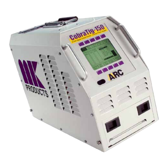
INTRODUCTION ® The portable, lightweight CobraTig 150 SM with SmartArc provides the automatic control you need to deliver repeatability, verification and traceability in high-integrity orbital and manual welding. SmartArc software develops a near ideal weld procedure through the use of our Automatic Procedure Generator. Just enter the tube outside diameter and wall thickness... -
Page 9: Technical Information
Section 1 Technical Information Line Power: 100VAC 50/60 Hz Single Phase, 15A (+/- 10%) 120VAC 50/60 Hz Single Phase, 15A 208-220/230-240VAC 50/60 Hz Single or Three Phase,30A Output Current: 0.1~150A (+/- 1%), Constant or Pulsed Minimum Arc Starting: 0.5 to 25 Amps Pulse Rate: 0.01 to 2.25 Seconds Per Pulse Arc Voltage: 65VDC Open Circuit, up to 26 welding VDC Loop Response: 1.5 KHz... -
Page 10: Connections
Section 4 Connections Input Power The CobraTig 150 SM can operate on any of four different input power values: 100VAC, 120VAC, 208-220/230-240VAC Single Phase and, 208- 220/230-240VAC Three Phase. Attached to the unit is a 12ft power cable that comes wired from the factory ready for 120VAC. Even though the installed plug is only three prongs, there are four wires in the cable, ready for three phase power. - Page 11 In order to update the firmware version in the CobraTig® 150, the following items are needed: • CobraTig 150. • PC/Laptop running Windows (Mac not supported). • Null Modem Cable (Female DB9 to Female DB9 ) and/or Serial to USB Adapter Cable •...
-
Page 12: Operation
Modem serial cable. View the CobraTig 150 MAIN MENU and inspect for the new firmware version number. 6. Installation Complete Section 5 OPERATION To operate the CobraTig 150 SM portable orbital welding unit, plug in any standard MK Orbital weldhead to the rear panel, and perform the basic setup procedures associated with collets, tungsten, and concentricity. -
Page 13: Main Menu
RS-232 Data Connector The CobraTig uses a DB-9 connector to communicate with an External PC. The wiring for this plug is “cable/null” modem wiring (female connector both ends). Section 6 Main Menu This is the starting menu for the CobraTig 150 SM orbital welder. It is from this menu that all the other menu displays and screens are accessible. - Page 14 • Press F4 or F9 and scroll to Curr. L. (A), low weld current in amps. • Press F5 or F10 and enter Low current value from 0.2~150 amps. • Press F4 or F9 and scroll to Pulse H. (S), high weld current pulse time.
-
Page 15: Weld Orbital
of the scale. Also, there is a change in the sound once the bottom of the scale has been reached. The sound changes from a single beep to a triple beep. Section 8 Weld Orbital From the MAIN MENU screen press this button to select orbital welding. Once at the WELD ORBITAL screen, use the RECALL PROGRAM button at the bottom of the screen to select from the library of customer designed and saved procedures, or return to the MAIN MENU and use the APG (Auto... -
Page 16: Recall Program
Section 9 Recall Program Press the RECALL PROGRAM in order to access the library of operator saved weld procedures. NOTE: If the currently used procedure is not saved, a warning screen of text will prompt for a ‘YES’ or ‘NO’ answer: this is the OVERWRITE screen. -
Page 17: Save Program
If the current weld program is a temporary, unsaved/modified program, the RECALL screen will be blank. This indicates that the current weld program has not been saved to any location. However, if the current weld program is from one of the saved locations, this screen will display the location it is presently saved at. -
Page 18: Auto Program Generator
If the current procedure is to be saved at this location, press “YES”. If this location is to be emptied, and the saved weld procedure erased, press “EMPTY ONLY”. If nothing is to be done with this location, and you need to return to the SAVE PROGRAM MENU, press “NO”. Scroll Right Each time this button is pressed, the locations of where each weld procedure is saved or can be saved to, will move three numbers to the... -
Page 19: Print Menu
some basic tube or pipe variables, the CobraTig 150 SM digital controller can generate and produce a near ideal weld procedure. The following menu will guide the operator through basic fields of information entry. Beginning with selections for tube or pipe and diameter and wall thickness. - Page 20 Print Graph This function works with the Printer After Welds function. Pressing this button toggles the command from YES (prints weld procedure parameters plus entire weld graph), to NO (prints weld procedure parameters only). Paper Feed Press and hold this button down in order to feed paper through the printer driver mechanism.
-
Page 21: Calibration Menu
This will give a weld procedure printout, first showing the description of the procedure, followed by the all the welding parameters, then by Limit and Deviation parameters, then by the actual strip chart of the weld amperage, arc voltage and motor speed. Program List Press this button to printout the complete listing of all the weld procedures saved in the memory of the unit. - Page 22 Connect an external DC voltage power supply to the shunt connectors labeled ‘ARC VOLTAGE’ and adjust to 1.8 VDC input. Reference the VDC bar graph on the LCD screen, press the 1.8 VDC button, this will set the calibration. Set the input to 18.0 VDC and repeat the above process. The procedure will cycle through twice for an average reading and setting, then quit when ready.
-
Page 23: Communication Menu
MOTOR Calibration report MOTOR gain: 0.0% Zero offset: 0.00 RPM TACH gain: 0.0% Zero offset: 0.00 RPM NOTE: If all values for MOTOR or WELDER calibration are zeros, it means that he calibration did not complete successfully and is not valid. Start Calibration Press this button to start the weldhead calibration procedure. -
Page 24: Setup Menu
Save Menu Press this button to change to the SAVE MENU. Xmit Channel This button will toggle between two choices of transmission. Either Infra Red or Wired Cable. Start Receive To begin transmitting a procedure to another machine, press this button. Scroll Left Each time this button is pressed, the locations of where each weld procedure is saved or can be saved to, will move three numbers to the... -
Page 25: Diagnostic Menu
Increase S/N This button will INCREASE the starting serial number of the next orbital weld. The serial number is incremented before every weld, so use one number less than actual number of next weld. Higher Contrast Press this button to increase the contrast for the LCD screen. This will make the display darker as the number increases. - Page 26 Change Hour Press to increase the hour of the day. In 12 Hour mode, the AM/PM will change automatically. 12-Hour Range: 1 -12 AM & 1 - 12 PM 24-Hour Range: 0 - 23 Change Minute Press to increase the minute of the hour. Once the end of the range is reached, the sequence will revert again.
- Page 27 THIS PAGE INTENTIONALLY BLANK...
- Page 28 16882 Armstrong Ave. Irvine, CA 92606 DATE: August 1, 2010 Tel (949)863-1234 Fax (949)474-1428 www.mkproducts.com...
- Page 29 16882 ARMSTRONG AVE. IRVINE,CA 92606 TEL (949) 863-1234 FAX (949) 474-1428 WWW.MKPRODUCTS.COM...
Need help?
Do you have a question about the CobraTig 150 SM 254-153 and is the answer not in the manual?
Questions and answers