Advertisement
Quick Links
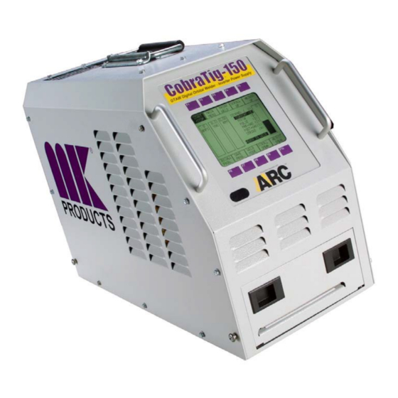
CobraTig
150
®
Calibration Procedure
Document 031-0181 Rev B
CAUTION
Performing the following Tests and Calibration require the operator to be
near HIGH VOLTAGES and HIGH CURRENTS. Operator must be familiar
with working in this environment and exercise caution during this
procedure to avoid any shock hazards.
MK Products, Inc.
16882 Armstrong Ave., Irvine, CA 92606 (949) 863-1234
Advertisement

Summary of Contents for MK Products CobraTig-150
- Page 1 Performing the following Tests and Calibration require the operator to be near HIGH VOLTAGES and HIGH CURRENTS. Operator must be familiar with working in this environment and exercise caution during this procedure to avoid any shock hazards. MK Products, Inc. 16882 Armstrong Ave., Irvine, CA 92606 (949) 863-1234...
-
Page 2: Equipment Needed
1. EQUIPMENT NEEDED o CobraTig 150 and Orbital Weldhead. o Calibration Kit (p/n 005-0251) o 30V / 5A DC External Power Supply and Banana Test Leads o Digital MultiMeter (Fluke 8060A or Equivalent) and Test Leads o Water Recirculator o Small Plastic Flathead Screwdriver o 1/4”... -
Page 3: Equipment Setup
Please read this procedure in its entirety before performing any work 2. EQUIPMENT SETUP CobraTig150 Determine input power available and wire input power plug accordingly if not already provided that way. See Appendix A for proper configuration of input power and internal jumper selections. Do not apply power to the CobraTig 150 until directed to do so. - Page 4 COBRATIG-150 CALIBRATION 3.1 Current-Voltage-Demand Offset Adjustment Before starting Calibration, print out the current Weldhead and Motor Calibration from the calibration menu (Later this can be compared with your new calibration data.) Meter (DMM) Setting Scale: mV, Mode: DC 3.1.1 Using a ¼” hex wrench, remove all the screws from the cover of the CobraTig150.
- Page 5 3.1.3 Apply input power to CobraTig150 and switch power on with breaker on back of unit. Using the small plastic flathead screwdriver, Adjust R24 (Current Offset) of the Power Supply Control Board until a reading in the range of (-2 mV to +2mV) is obtained on meter.
- Page 6 3.1.5 Adjust R130 (Voltage offset) until a reading in the range of (-2 mV to +2mV) is obtained on meter. (Figure 4) R130 Location Fig. 4 – Trimpot R130 is used to adjust voltage at TP7 3.1.6 Leaving the Meter GND(-) lead on TP1, move the Meter POS(+) to TP8.
- Page 7 3.1.8 Re-Check all three test points (TP3, TP7, and TP8) to verify that the settings are maintained. Make additional adjustments if needed. Notes: R24 is used to adjust voltage at TP3 R130 is used to adjust voltage at TP7 R139 is used to adjust voltage at TP8 3.1.9 Remove all Meter leads from Test Points in CobraTig150.
- Page 8 Weldhead Control Cable to the back of the Cobratig150. (See Appendix B) (Figure 8) Fig. 8 - Calibration Setup 3.2 Weldhead Motor Calibration The COBRATIG-150 Software allows push-button adjustments of the COBRATIG-150 calibration parameters. 3.2.1 From the MAIN MENU, press the CALIB MENU [F7] key.
- Page 9 3.3 Arc Voltage Calibration Connect the DC power supply to the Input Voltage connectors of the Calibration Kit shunt box. (POS to RED+, NEG to BLACK-). Connect voltage meter DMM (Digital Multi Meter) across supply leads to monitor voltage if your DC supply does not have a digital display.(See Appendix C / Figure 9) Meter (DMM) Setting Scale: Volts (V), Mode: DC...
- Page 10 3.4 Current Calibration CAUTION: Disconnect DC power supply and/or DMM from their power source until an Arc is established. 3.4.1 Connect leads from the DMM (POS to RED+) (NEG to BLACK-) to the Current Shunt of the Calibration Kit Shunt Box, make sure meter is off until weld arc is started.
- Page 11 APPENDIX A-1 Setup for using 100 VAC (Japan) With an input of 100 VAC, you must use the single phase plug (5- 15P). You must connect the jumper inside the CobraTig 150 to the appropriate terminals, and make sure it is facing the correct way. You must also connect the voltage selector lead to it’s appropriate terminal.
- Page 12 APPENDIX A-2 Setup for using 120 VAC With an input of 120 VAC, you can use either a 15 Amp single phase plug (5-15P), or a 30 Amp single phase plug (L5 – 30P). You must connect the jumper inside the CobraTig 150 to the appropriate terminals, and make sure it is facing the correct way.
- Page 13 APPENDIX A-3 Setup for using 230/240 VAC With an input of 230/240 VAC, you can use either a single phase (L6- 30P) plug or a three phase (L15 – 30P) plug. You must connect the jumper inside the CobraTig 150 to the appropriate terminals, and make sure it is facing the correct way.
- Page 14 APPENDIX A-4 Setup for using 208/220 VAC With an input of 208/220 VAC, you can use either a single phase (L6- 30P) plug or a three phase (L15 – 30P) plug. You must connect the jumper inside the CobraTig 150 to the appropriate terminals, and make sure it is facing the correct way.
- Page 15 APPENDIX A-3 Setup for using 230/240 VAC With an input of 230/240 VAC, you can use either a single phase (L6- 30P) plug or a three phase (L15 – 30P) plug.
- Page 16 VOLTAGE METER...
- Page 17 ·...


Need help?
Do you have a question about the CobraTig-150 and is the answer not in the manual?
Questions and answers