
Related Manuals for Ozito MWR-090


Summary of Contents for Ozito MWR-090
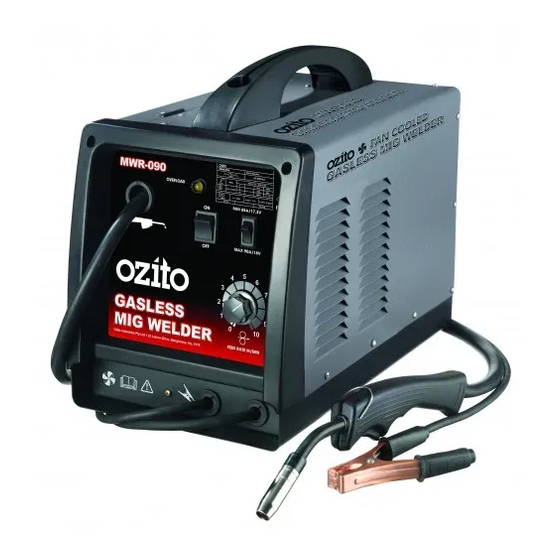
- Page 1 MIG WELDER Gasless Instruction Manual 3 Year Replacement Warranty MWR-090 CAUTION: Read this instruction manual before using this tool. 0112 www.ozito.com.au To view the full range visit:...
-
Page 2: Specifications
SPECIFICATIONS - MODEL NO. MWR-090 Input: 230-240V ~ 50Hz Current range: 65 – 90 Amp Duty cycle: 25% @ 65A Welding wire size: 0.8 - 0.9mm Flux-cored wire Insulation type: Earthed appliance (class I) Welding wire spool weight: 0.2kg - 5kg Weight: 16.6kg... -
Page 3: Table Of Contents
TABLE OF CONTENTS SPECIFICATIONS…………………………………………… Page 2 KNOW YOUR PRODUCT…………………………………. Page 2 INTRODUCTION……………………………………………. Page 4 ELECTRICAL SAFETY……………………………………… Page 4 GENERAL SAFETY INSTRUCTIONS……………………… Page 5 SAFETY INSTRUCTION FOR WELDERS…………………. Page 6 ADDITIONAL SAFETY INSTRUCTIONS FOR MIG WELDERS……………………………………….. Page 7 ASSEMBLY…………………………………………………… Page 8 OPERATION…………………………………………………... -
Page 4: Introduction
The electric motor has been designed for 230V and 240V only. Always check that the power supply corresponds to the voltage on the rating plate. Note: The supply of 230V and 240V on Ozito tools are interchangeable for Australia and New Zealand. -
Page 5: General Safety Instructions
GENERAL SAFETY INSTRUCTIONS WARNING! Read all instructions. Failure to follow all instructions listed below may result in electric shock, fire and/or serious injury. The term "power tool" in all of the warnings listed below refers to your mains- operated (corded) power tool or battery-operated (cordless) power tool. Save these instructions 1. -
Page 6: Safety Instruction For Welders
GENERAL SAFETY INSTRUCTIONS (cont.) 13. Do not abuse the cord. Never carry the equipment by its cord or pull it to disconnect from the socket. Keep the cord away from heat, oil and sharp edges. 14. Store equipment. When not in use, equipment should be stored in a dry, locked up or high place, out of reach of children. -
Page 7: Additional Safety Instructions For Mig Welders
ADDITIONAL SAFETY INSTRUCTIONS MIG WELDERS This appliance is not intended for use by persons (including children) with reduced physical, sensory or mental capabilities, or lack of experience and knowledge, unless they have been given supervision or instruction concerning use of the appliance by a person responsible for their safety. -
Page 8: Assembly
ASSEMBLY Fitting the Welding Wire 0.2kg coil (Fig.1) This welder is supplied with a .2kg coil of gasless welding wire (c). Welding wire up to 5kg can be fitted to this welder. (d) (e) Wire Drive Shaft (a) Drive washer(d) Fig. - Page 9 ASSEMBLY (cont.) Drive Roller Assembly Descriptions (Fig.2) Adjustable Pressure Screw Pressure Arm Pressure Screw Arm Pressure Roller Conduit Liner Inlet Guide Wire Drive Roller Wire Drive Roller Bracket Fig. 2 Setting the Wire Drive Roller Size Release the pressure of the pressure roller (m) by loosening the pressure screw (g) anti-clockwise (Fig.3).
- Page 10 ASSEMBLY (cont.) Caution: Do not over tighten the wire drive roller bracket (j) as this could result in damage to the welder. Fig. 8 Adjusting Drive Roller Pressure The pressure roller (m) applies pressure to the wire drive roller (k) via the adjustable pressure screw (g) and pressure arm (h).
- Page 11 ASSEMBLY (cont.) WARNING! Make sure the earth clamp is not touching you and out of your way. The electrode wire will be at welding voltage whilst it is being fed through the system. Keep the MIG Torch away from your eyes and face. Feeding the Welding Wire (Fig.11) 1.
-
Page 12: Operation
OPERATION Adjusting the Wire Speed and Welding Current (Fig.13) The wire speed can be controlled by the wire speed adjustment knob (9). The wire speed adjustment knob (9) controls the welding current via the welding wire, this determines the speed of the wire feed motor and the rate of the welding wire to your welding job. - Page 13 OPERATION (cont.) Overload reset button and fuse Inside the side cover (13) you will find a fuse (Fig. 17) and fuse holder. In the event that the welder is overloaded or has received a power surge the welder may turn itself off for internal components protection.
-
Page 14: Maintenance
Welding Power Source. This may result in arcing between the parts and their eventual failure. Note: Ozito Industries will not be responsible for any damage or injuries caused by the repair of the tool by an unauthorised person or by mishandling of the tool. -
Page 15: Troubleshooting
TROUBLESHOOTING FAULT CAUSE REMEDY Have an authorised Torch trigger switch Mains supply voltage electrician or power tool is ON but when the leads are disconnected torch trigger switch is or broken. repairer replace the depressed, nothing faulty parts. happens. Have an authorised Fuse on Printed Circuit Board is blown. - Page 16 TROUBLESHOOTING (cont.) FAULT CAUSE REMEDY Torch trigger leads Wire continues to Repair or replace Torch / shorted. feed when torch trigger lead. trigger is released. Printed Circuit Have an authorised Board Faulty. electrician or power tool repairer replace the faulty parts. Power Source Over Heat Cease welding and allow OVERHEAT LED...
- Page 17 TROUBLESHOOTING (cont.) FAULT CAUSE REMEDY Adjust voltage and Incorrect voltage and Irregular weld shape. current settings. current by adjusting the Min/Max Control Switch Convex, Arc voltage positions and the Wire too low, Concave voltage too high. speed adjustment knob. Replace torch tip. Wire is wandering.
-
Page 18: Spare Parts
SPARE PARTS Please contact your local Bunnings Special Orders Desk to order the required spare parts. Most common spare parts listed below Spare Part Part No. Mig Torch Assembly SPMWR090-03 On/Off Switch Assembly SPMWR090-05 Hi/Low Switch Assembly SPMWR090-06... - Page 19 CIRCUIT DIAGRAM...
-
Page 20: Description Of Symbols
DESCRIPTION OF SYMBOLS Volts Hertz Alternating current Watts m/min Revolutions or Amperes reciprocation per minute Rated AV input voltage load duration rate (with tolerance ±10%) Rated maximum input current Maximum effective input current 1max 1eff Non-load voltage On-load voltage Vmax Max. -
Page 21: Pack Contents
Please recycle packaging where facilities exist. Check with your local council authority for recycling advice. PACK CONTENTS 1 x Gasless MIG Welder MWR-090 1 x Welding mask 1 x Combination chipping hammer and wire brush 1 x 0.8mm-0.9mm Wire feed roller (fitted to the welder) 1 x 0.2kg Welding wire... - Page 22 OZITO INDUSTRIES PTY LTD AUSTRALIA (Head Office) 1 - 23 Letcon Drive, Bangholme, Victoria, Australia 3175 Telephone: 1800 069 486 Facsimile: +61 3 9238 5588 Website: www.ozito.com.au Email: enquiries@ozito.com.au...
-
Page 23: Warranty
If the tool shows signs of damage or defects caused by or resulting from abuse, accidents or alterations. • Failure to perform maintenance as set out within the instruction manual. • If the tool is disassembled or tampered with in any way. OZITO Australia/New Zealand (Head Office) 1-23 Letcon Drive, Bangholme, Victoria, Australia 3175...
Need help?
Do you have a question about the MWR-090 and is the answer not in the manual?
Questions and answers