Table of Contents
Advertisement
inSTAllATion AnD MAinTEnAncE inSTRucTionS
BEAM355, BEAM355S Single-ended
Reflected Type Projected Beam Smoke Detector
SPEcificATionS
GEnERAl
Range:
Sensitivity:
Spacing:
Response Time:
Trouble Conditions:
Test/Reset Features:
Indicators:
Style 7 Operation:
ENVIRONMENTAL
Temperature:
Humidity:
Mechanical
Shipping Weight:
Shipping Size:
Mounting:
Wiring:
Adjustment Angle:
Paintable Trim Ring:
ELECTRICAL
Voltage:
Standby Current:
External Supply (BEAM355S only):
Remote Output (alarm)
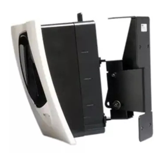
GEnERAl DEScRiPTion
Fire•Lite Model BEAM355/BEAM355S is a long range projected beam smoke
detector designed to provide open area protection. It is to be used with UL-
listed compatible control panels only. The detector consists of a transmitter/
receiver unit and a reflector. Smoke entering the area between the transmit-
ter/receiver and reflector causes a reduction in signal. When the obscuration
reaches alarm thresholds (chosen at the transmitter/receiver unit), the de-
tector generates an alarm signal. Complete blockage of the beam causes a
trouble signal. Slow changes in obscuration due to a build up of dirt or dust
on the lens of the detector are compensated for by a microcontroller that con-
tinuously monitors the signal strength and periodically updates the alarm and
F300-29-00
16 to 230 Feet (5 to 70m)
230 to 328 Feet (70 to 100m) using optional accessory BEAMLRK
25% to 50% Total Obscuration in 6 levels
Level 1 = 25%
Level 2 = 30%
Level 3 = 40%
Level 4 = 50%
Level 5 = 30% to 50% (Acclimate)
Level 6 = 40% to 50% (Acclimate)
30 to 60 Feet (9.1 to 18.3m)
ALARM: - 20 seconds typical; TROUBLE: - 30 seconds typical
Beam Blockage (96% or More Obscuration)
Improper Initial Alignment
Self-compensation limit reached (service needed)
In Alignment mode
Integral Sensitivity Test Filter (BEAM355S only, requires additional external power supply)
Sensitivity Filter (Incremental scale on reflector)
Local Alarm Test Switch
Local Alarm Reset Switch
Remote Test and Reset Switch Capability
ALARM - Remote Output, Local LED (red);
TROUBLE - Remote Output, Local LED (yellow), Blink Pattern Indicates Trouble Diagnostics
NORMAL OPERATION - Local LED (flashing green with communication)
ALIGNMENT AIDS - Optical Gunsight (coarse adjustment), 00 to 99 Digital Display (fine adjustment)
SENSITIVITY - Digital Display Readout in Percent Obscuration
On-board isolators provide style 7 operation. (may be disabled via shunts on circuit board)
–22°F to 131°F (–30°C to 55°C); NOTE: for applications below 32°F (0°C) see Special Applications section of this manual.
10% to 93% RH Non-condensing
3.9 lbs. (1.77 kg)
15" × 10.5" × 6.5" (381mm × 267mm × 165mm)
Wall only without optional accessories
Plug-in Terminal Blocks (12 to 22AWG)
±10° Horizontal and Vertical
May be painted using enamel or acrylic type paints
15 to 32 VDC
Avg. Standby -
Max. Alarm (LED on):
Max. Trouble (LED on):
Max. Alignment:
VOLTAGE - 15 to 32 VDC
CURRENT - 0.5A Max.
VOLTAGE - 15 to 32 VDC; NOTE: Output voltage same as device input voltage.
CURRENT - 15mA maximum; 6mA minimum; NOTE: Output current is limited by 2.2Kohm resistor
2mA Max. (1 communication every 5 sec. LED flashing, SLC @ 24 V)
8.5mA Max.
4.5mA Max.
20mA Max.
trouble thresholds. When the self-compensation circuit reaches its limit, the
detector generates a trouble signal, indicating the need for service.
Three LEDs on the detector indicate the current status: a red LED for alarm, a
yellow LED for trouble, and a blinking green LED for standby operation. Note:
The panel controls the status of the red and green LEDs. The local reset but-
ton is accessible by removing the outer paintable trim ring. The yellow LED
will blink in specific patterns to provide a diagnostic aid when diagnosing the
cause of a trouble signal. It will also blink the amount of drift compensation
that has been used at the conclusion of the test. Trouble signals automati-
cally reset upon removing the cause of trouble. Red and yellow LEDs can be
1
One FireLite Place
Northford, CT 06472
Phone: 203.484.7161
I56-2425-007R
Advertisement
Table of Contents

Related Manuals for Honeywell FireLite BEAM355


Summary of Contents for Honeywell FireLite BEAM355
- Page 1 GEnERAl DEScRiPTion trouble thresholds. When the self-compensation circuit reaches its limit, the Fire•Lite Model BEAM355/BEAM355S is a long range projected beam smoke detector generates a trouble signal, indicating the need for service. detector designed to provide open area protection. It is to be used with UL- listed compatible control panels only.
-
Page 2: Special Applications
6500-SMK remotely connected to the remote Alarm and Trouble outputs. These outputs mimic the functions of the detector’s red and yellow LEDs. In addition to these The 6500-SMK allows the transmitter/receiver to be mounted to the 6500- indicators, there is a dual digital display that reads 00 to 99. This display is MMK heavy duty multi-mount kit. - Page 3 fiGuRE 3. SloPED cEilinG (ShED TyPE): Some fire codes specify spacing on a given center-to-center distance between detectors under ideal conditions. This spacing is based on rooms with smooth 3 F T . ceilings and no physical obstructions between the contents being protected ( 0 .9 M ) M A X and the detectors.
-
Page 4: Mounting Considerations For Single Ended Beam Detectors
line of sight to the transmitter/receiver unit. The maximum tolerance for non- detector and the reflector. perpendicular mounting locations is 10°. See Figure 5b. If the reflector cannot In cases where operation through panes of glass cannot be avoided some spe- be mounted within 10°... -
Page 5: Pre-Alignment Checklist
/ AliGnMEnT Reference Figures 10 through 14 for installation, alignment, and maintenance. The alignment of the BEAM355/BEAM355S is divided into four steps: coarse alignment, fine adjustment, final gain adjustment, and final verification. It is necessary for all four steps to be executed properly to ensure proper alignment of the product. -
Page 6: Step 1. Coarse Alignment
STEP 1. coARSE AliGnMEnT NOTE: The alignment procedure is not complete yet. Refer to Figures 11 and 12 for this step. At this time it is possible to set the sensitivity of the detector using the sen- sitivity switch and digital display. See the Sensitivity Selection section of this Ensure that both of the optics lock-down screws are loosened so that the manual for further details. - Page 7 fiGuRE 10. SwiTch locATionS fiGuRE 13. houSinG ScREw locATionS SCREW LOCATIONS ALIGNMENT SENSITIVITY TEST RESET RESET SWITCH STYLE 7 ISOLATOR SHUNTS C0266-00 (SHOWN DISABLED) ShoRT ciRcuiT iSolATion C0263-00 The detector includes an on-board circuit isolator that allows for NFPA72 style fiGuRE 11.
-
Page 8: Maintenance
Disable the zone or system undergoing maintenance to The remote test station can be used with the BEAM355/BEAM355S beam prevent unwanted alarms. smoke detector. Follow instructions included with the test station for proper Detectors must be tested after installation and following periodic maintenance. -
Page 9: Appendix I. Operation Modes And Troubleshooting Guide
Fail Result Local Test On until reset or Blink Blink Panel or RTS451/ Remains in fault until reset or time-out (BEAM355) time-out KEY test input Fail Local Test Blinking the amount Panel or RTS451/ Remains in alarm until reset or time-out... -
Page 10: Appendix Ii. Detector Drilling Template
APPEnDix ii. DETEcToR DRillinG TEMPlATE 6.190˝ (157 mm) 4.345˝ (110 mm) Scale = 1:1 F300-29-00 I56-2425-007R... - Page 11 F300-29-00 I56-2425-007R...
-
Page 12: Appendix Iii. Reflector Drilling Template
APPEnDix iii. REflEcToR DRillinG TEMPlATE 5.512˝ (140mm) 8.465˝ (215mm) Scale = 1:1 F300-29-00 I56-2425-007R... - Page 13 Please refer to insert for the Limitations of Fire Alarm Systems fcc Statement This projected beam smoke detector has been tested and found to comply with not installed and used in accordance with the instruction manual, may cause the limits for a Class B digital device, pursuant to part 15 of the FCC Rules. harmful interference to radio communications.