Table of Contents
Advertisement
Installation, Operation and Service Instructions
Installation, Operation
and Service Manual
for the
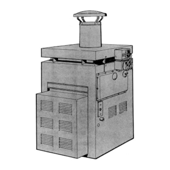
XL-3 Oil-Fired
Pool Heater
Models DP2000
and DP3000
FOR YOUR SAFETY: This product must be installed and serviced by a professional service technician,
qualified in pool heater installation and maintenance. Improper installation and/or operation could
create carbon monoxide gas in flue gases which could cause serious injury, property damage, or death.
Improper installation and/or operation will void the warranty.
If the information in this manual is not followed exactly, a fire or explosion may result
causing property damage, personal injury or loss of life.
Do not store or use gasoline or other flammable vapors and liquids in the vicinity of this or
any other appliance.
• Do not try to light any appliance.
• Do not touch any electrical switch; do not use any phone in your building.
• Immediately call your gas supplier from a nearby phone. Follow the gas supplier's
instructions.
• If you cannot reach your gas supplier, call the fire department.
Installation and service must be performed by a qualified installer, service agency, or gas
supplier.
WARNING
WHAT TO DO IF YOU SMELL GAS
Advertisement
Table of Contents

Subscribe to Our Youtube Channel
Related Manuals for Laars DP2000


Summary of Contents for Laars DP2000
- Page 1 Service Manual for the XL-3 Oil-Fired Pool Heater Models DP2000 and DP3000 FOR YOUR SAFETY: This product must be installed and serviced by a professional service technician, qualified in pool heater installation and maintenance. Improper installation and/or operation could create carbon monoxide gas in flue gases which could cause serious injury, property damage, or death.
-
Page 2: Table Of Contents
Page 2 TABLE OF CONTENTS SECTION 1. SECTION 4. General Information Maintenance Warranty ............3 Trouble-Shooting ........12 Cleaning the Heat Exchanger ....13 SECTION 2. Trouble-Shooting Guide ......13 Operating Sequence ........14 Assembly & Installation Trouble-Shooting ........14 Shipping Damage ......... -
Page 3: General Information
The XL-3 pool heater is sold with a limited warranty. Details are specified on the back page of this manual. Make warranty claims to an authorized Laars representative or to the factory. Claims must include the serial number and model of the heater, installation date and name of the installer. - Page 4 Page 4 Figure 2. Non-Combustible Platform. Figure 4. Inner Stack. pipe. To assemble the inner stack, remove the tape and small envelope from the sheet metal coil. Expand the coil until the holes on each end are aligned. Use the two screws supplied in the small envelope to secure the ends together.
-
Page 5: Outdoor Installation
14. Rotate the conduit assembly and attach it to the 2C. Outdoor Installation switch box. Tighten the compression nut on the Install the Laars XL-3 heater in the open, or in an other end. enclosure without a roof. The chimney cap supplied with the heater must be installed. -
Page 6: Clearances
Page 6 Figure 8. Venting, Indoor Installation. the room containing the heater must have its own clean and consistent flame. When the system is combustion and ventilation openings as described properly adjusted, the pressure in the stack below the below (see Fig. 8). draft control will be approximately minus .03"... -
Page 7: Oil Piping
Model DP Oil-Fired Heater Page 7 Figure 9. Combustion Air, Indoor Installation. openings communicating with living areas. Oil Piping All XL-3 heaters are equipped with two-stage fuel units. Water Pik Technologies recommends a two-pipe system with a supply line and a return line between the heater and the tank (see Fig. -
Page 8: Water Piping
Page 8 Figure 11. Oil Filter Installation. Figure 13. Thermometer Placement. using an Allen wrench. Check the instructions universal flange couplings on the heater as shown attached to the fuel pump for proper fuel connections. below. The inlet and outlet ports on the heater are Compression fittings are not recommended. -
Page 9: Pressure Relief Valve
Model DP Oil-Fired Heater Page 9 The bypass valve is properly adjusted. Remove the handle on the valve, or place a warning tag “DO 2H. Automatic Chlorinators NOT TOUCH THIS VALVE.” A concentration of chlorine in the heater can be Install a check valve and heat sink pipe in the very destructive. -
Page 10: Time Clock Installation
2K. Special Pressure Switch A special pressure switch is required if the XL-3 is installed more than 3 feet below the surface of the pool. Consult a Laars representative or contact the factory. IMPORTANT: Before starting the heater on a new installation, relieve all air from the system by running the filter pump for at least 15 minutes. -
Page 11: Setting The Time Clock
Model DP Oil-Fired Heater Page 11 SHOULD START THE OIL BURNER. (see NOTE below). If a one-pipe system is used, it must be thoroughly purged of air using the vent Check the operation of the burner. Make sure of plug on the oil pump. the proper air adjustment. -
Page 12: Winter Shutdown
Page 12 time clock stops. NOTE: The XL-3 heater is not designed for continuous use to combat freezing temperatures. Keep When the water reaches the temperature level the temperature at a minimum 70°F (21°C) or shut the on the thermostat, the heater will turn off heater down completely. -
Page 13: Cleaning The Heat Exchanger
Model DP Oil-Fired Heater Page 13 Heater Does Not Maintain the Desired Water Remove the heater top assembly and flue Temperature collector. Is the temperature control set high enough? Remove the inspection hole cover (see Fig. 19). Is the filter cycle setting on the time clock long Use an ordinary kitchen brush to brush across the enough to permit the heater to raise the top of the heat exchanger between the tube fins. -
Page 14: Operating Sequence
Page 14 a bypass plug must be installed in the fuel pump. The plug is supplied with the oil burner. There is a decal located on the fuel pump showing where the bypass plug goes. If a fuel unit is set up for a two-pipe system, but is actually connected to a one-pipe system, the pressure in the fuel pump builds up to over 300 psi when the burner turns on. -
Page 15: Burner Tries To Start, But The Primary Control 10 Shuts Off (Either Motor Or Transformer Or Both Come On)
Model DP Oil-Fired Heater Page 15 Is there power to the heater? Have you checked transformer is providing spark at the electrodes, the reset buttons on the motor and primary go to step 3. control? Lift the ignition transformer and make sure the Place a jumper wire across the two terminals on motor rotates freely. -
Page 16: Regular Maintenance
Page 16 Figure 21. Electrode Adjustment. Measure the C0 - If it measures less than 11.5%, Lacking proper instruments, a temporary fuel-air decrease the air supply. If it measures higher than adjustment can be made. Close the end shutter 12.5%, increase the air supply. and then slowly close the air bank until the heater When the fuel-air setting is correct, there will be starts to smoke. -
Page 17: Service Information
Model DP Oil-Fired Heater Page 17 Replace the oil nozzle once a season (see the oil Attach the cad cell wires to the primary burner Manual). control. Attach the thermostat wires to the primary Oil the burner motor every three months. Use control. -
Page 18: Parts List For Model Dp Oil-Fired Heater
Page 18 SECTION 6. Parts List for Model DP Oil-Fired Heater Model ORDER Model ORDER No. Description PART NO. No. Description PART NO. FUEL SYSTEMS FIRE BOX & JACKET COMPONENTS Oil Burner Assembly 2000 L0060000 Burner Tube Gasket N0006600 Oil Burner Assembly 3000 L0060100 Burner Support Bracket... - Page 19 Model DP Oil-Fired Heater Page 19 29 18...
-
Page 20: Limited Warranty
Laars factory. The liability of Water Pik Technologies above limitation or exclusion may not apply to you. shall not exceed the repair or replacement of defective...
Need help?
Do you have a question about the DP2000 and is the answer not in the manual?
Questions and answers
yes do not see a p/n for firebox DP2000
is there a fire box available for the DP2000 heater