Table of Contents
Advertisement
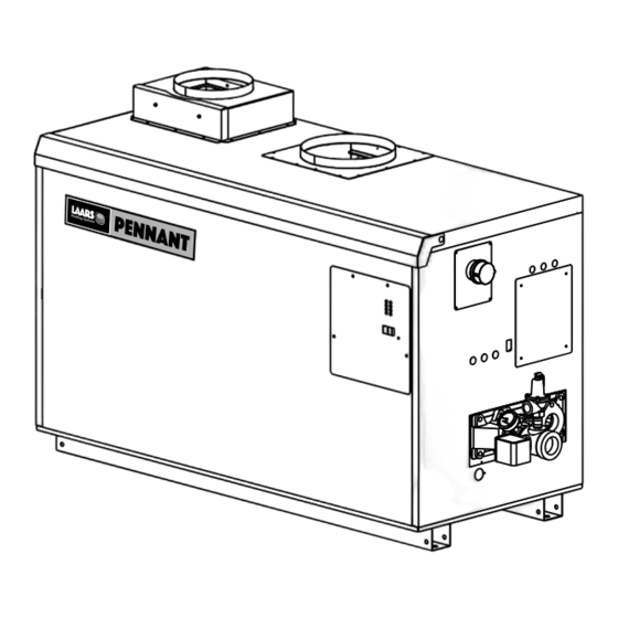
Installation and Operation Instructions
FOR YOUR SAFETY: This product must be installed and serviced by a professional service technician,
qualified in hot water boiler installation and maintenance. Improper installation and/or operation could
create carbon monoxide gas in flue gases which could cause serious injury, property damage, or death.
Improper installation and/or operation will void the warranty.
WARNING
If the information in this manual is not
followed exactly, a fire or explosion may
result causing property damage, personal
injury or loss of life.
Do not store or use gasoline or other
flammable vapors and liquids in the vicinity
of this or any other appliance.
WHAT TO DO IF YOU SMELL GAS
• Do not try to light any appliance.
• Do not touch any electrical switch; do not
use any phone in your building.
• Immediately call your gas supplier from a
nearby phone. Follow the gas supplier's
instructions.
• If you cannot reach your gas supplier, call
the fire department.
Installation and service must be performed by
a qualified installer, service agency, or gas
supplier.
H2311900D
Installation and Operation
Instructions for
Pennant
Pool Heater
Model PNCP
U.S. Reg. 2,765,423
AVERTISSEMENT
Assurez-vous de bien suivres les instructions
données dans cette notice pour réduire au
minimum le risque d'incendie ou d'explosion ou
pour éviter tout dommage matériel, toute
blessure ou la mort.
Ne pas entreposer ni utiliser d'essence ni
d'autres vapeurs ou liquides inflammables dans
le voisinage de cet appareil ou de tout autre
appareil.
QUE FAIRE SI VOUS SENTEZ UNE ODEUR DE GAZ:
• Ne pas tenter d'allumer d'appareils.
• Ne touchez à aucun interrupteur. Ne pas vous
servir des téléphones dansle bâtiment où vous
vous trouvez.
• Appelez immédiatement votre fournisseur de
gaz depuis un voisin. Suivez les instructions
du fournisseur.
• Si vous ne pouvez rejoindre le fournisseur de
gaz, appelez le sservice des incendies.
L'installation et l'entretien doivent être assurés par
un installateur ou un service d'entretien qualifié ou
par le fournisseur de gaz.
Document 3164D
™
Advertisement
Table of Contents
Troubleshooting

Related Manuals for Laars Pennant PNCP 500


Summary of Contents for Laars Pennant PNCP 500
- Page 1 Installation and Operation Instructions Document 3164D Installation and Operation Instructions for Pennant ™ Pool Heater Model PNCP U.S. Reg. 2,765,423 FOR YOUR SAFETY: This product must be installed and serviced by a professional service technician, qualified in hot water boiler installation and maintenance. Improper installation and/or operation could create carbon monoxide gas in flue gases which could cause serious injury, property damage, or death.
-
Page 2: Table Of Contents
LAARS Heating Systems Page 2 TABLE OF CONTENTS SECTION 1. SECTION 6. General Information Operating Instructions Introduction ............. 3 Sequence of Operation ......... 14 Model Identification ......... 3 Filling the Heater System ......15 Warranty ............4 Operating the Burner and Set Up ....15 Dimensions ............. -
Page 3: General Information
Laars Heating Systems warranty All electrical wiring is to be done in accordance may be voided. The installation must conform to the with the local codes, or in the absence of local codes, requirements of the local jurisdiction having with: 1). -
Page 4: Warranty
The covered by a limited warranty. The owner should fill location for the appliance should be chosen with out the warranty registration card and return it to Laars regard to the vent pipe lengths and external plumbing. Heating Systems. - Page 5 Pennant Pool Heater Page 5 Shipping Weight Size lbs. 1000 1250 1500 1750 Dimensions shown in inches cm VENT HORIZ. CONN. CONN. VENT SIZE PIPE 33½ 15¾ 40 5¾ 29¾ 76 32¾ 83 7¾ 20 8¾ 22 46 117 6 15 8 20 6 15 45½...
-
Page 6: Locating Heater With Respect To Pool System Loop
LAARS Heating Systems Page 6 1.6 Locating Heater with Respect to Pool SECTION 2. System Loop Venting and Combustion Air For the best results, the Pennant should be located within 15 feet (4.6m) of the pool system loop. 2.1 Combustion Air The pump is sized for 30 feet (9.1m) of piping. -
Page 7: Intake Combustion Air
(without the use of a power venter) are Laars horizontal wall terminal (see Table 2). When considered Category III vent systems. taken from the roof, a field-supplied rain cap or an elbow arrangement must be used to prevent entry of rain water (see Figure 2). -
Page 8: Common Venting Systems
2.3.1 Side Wall Vent Terminal applicable local codes, it is required that installers The Laars side wall vent hood (listed in Table 1) provide some means to prevent operation with a must be used when the heater is vented through a side blocked common vent. -
Page 9: Side Wall Combustion Air Terminal
Corrosion of and/or damage to the pool heater may requires that it be at least 12 inches (30 cm) result. The Laars side wall combustion air terminal above grade, but the installer may determine it (listed in Table 1) must be used when the unit takes its should be higher, depending upon local combustion air through a duct from a side wall. -
Page 10: Vertical Vent Terminal
Verify that the appliance is fitted for the proper least 12" (30cm) above the point at which it penetrates type of gas by checking the rating plate. Laars the roof, and high enough above the roof line to Heating Systems appliances are normally prevent blockage from snow. -
Page 11: Water Connections
Pennant Pool Heater Page 11 SECTION 4. 13" W.C (3.2kPa). The minimum inlet gas pressure is 5" W.C. (1.2kPa). Water Connections Refer to Table 7, size supply. Run gas supply line in accordance with all 4.1 Piping applicable codes. Hot water piping should be supported by suitable Locate and install manual shutoff valves in hangers or floor stands. -
Page 12: Automatic Chlorinators
LAARS Heating Systems Page 12 The Pennant Pool Heater is shipped with a field-installed mixing system, and must be piped in primary- secondary style, as shown. A remote pool temperature sensor and remote pool temperature high limit are wired to the Pennant, to be mounted in the pool water loop, as shown. -
Page 13: Main Power
Pennant Pool Heater Page 13 wiring terminal strip, which is located at the right side of the appliance. NOTE: All internal electrical components have been prewired. No attempt should be made to connect electrical wires to any other location except the field wiring strip. -
Page 14: Programming Control Parameters
LAARS Heating Systems Page 14 5.3.6 Heater Purge (Pump Delay) - Pd 5.3.2 Programming Control Parameters After a demand is satisfied, the pump will There are four (4) control parameters that may be continue to run for a preset length of time. That length set. -
Page 15: Filling The Heater System
Pennant Pool Heater Page 15 normally-open contact(s) of the airflow pressure After placing the unit in operation, the ignition switch(es). This allows the ignition module to proceed system safety shutoff device must be tested. with the ignition sequence. First, shut off the manual gas valve, and call the The blocked flue pressure switch senses the unit for heat. -
Page 16: High Altitude Adjustment And Set Up
LAARS Heating Systems Page 16 warm-up is complete and all safety devices are Pennant appliances for high altitude. High altitude verified, the gas valves open. If ignition doesn’t adjustment is accomplished by adjustment of the gas occur, check that there is proper gas supply. Wait valve manifold pressure and the air shutter(s). -
Page 17: Backwash Switch Operation
To place the heater into backwash mode proceed Improper use of the heater: The Laars PNCP as follows: pool heater is not designed for continuous use as Turn the backwash switch down to the “Filter a “anti-freezing”... -
Page 18: Maintenance
Drinking of alcoholic beverages before or Component Description during hot tub use can cause drowsiness, which could lead to unconsciousness and Only genuine Laars replacement parts should be used. subsequently lead to drowning. Caution • Pregnant women beware! Soaking in water Label all wires prior to disconnection when servicing above 102°F (39°C) can cause fetal damage... -
Page 19: Gas Valves
Pennant Pool Heater Page 19 only need replacement in very rare cases. If filter control provides for part-load start-up and the second replacement is needed, it should only be replaced with control brings the heater to full rate, after the first a factory part. -
Page 20: Heat Exchanger Coil
If the tubes show signs of scaling, servicing the heat exchanger. clean the internal surface. Laars offers a tube cleaning kit part number R0010000. The Pennant has a pre-mixed burner system. -
Page 21: Delayed Ignition - Possible Causes
Pennant Pool Heater Page 21 strong piercing smell indicates poor combustion and 8.2 Delayed Ignition - Possible Causes generally a lean mixture - low CO or high O . The A defective burner can cause a delayed ignition. should be 8% (natural gas, 9.2% LP) at high fire. If the gas supply pressure is proper and the gas valves To check the CO , first verify that the supply gas... -
Page 22: Replacement Parts
Replacement Parts Only genuine Laars replacement parts should be used. 9.1 General Information To order or purchase parts for the Laars Pennant, contact your nearest Laars dealer or distributor. If they cannot supply you with what you need, contact Customer Service (see back cover for address, telephone and fax numbers). - Page 23 Pennant Pool Heater Page 23...
- Page 24 LAARS Heating Systems Page 24...
- Page 25 Pennant Pool Heater Page 25...
- Page 26 LAARS Heating Systems Page 26...
- Page 27 Pennant Pool Heater Page 27...
- Page 28 LAARS Heating Systems Page 28 Figure 9. Sheet Metal Components.
- Page 29 Pennant Pool Heater Page 29 Figure 10. Internal Components.
- Page 30 LAARS Heating Systems Page 30 See pump chart below for pump numbers. Figure 11. Heat Exchanger Components.
- Page 31 Pennant Pool Heater Page 31 SECTION 10. Wiring Diagrams Figure 12. Pennant 500 - 1000 Ladder Diagram.
- Page 32 LAARS Heating Systems Page 32 Figure 13. Pennant 1250 - 2000 Ladder Diagram.
- Page 33 Pennant Pool Heater Page 33 Figure 14. Pennant 500 - 1000 Wiring Schematic.
- Page 34 LAARS Heating Systems Page 34 Figure 15. Pennant 1250 - 2000 Wiring Schematic.
- Page 35 Pennant Pool Heater Page 35 Figure 16. Field Wiring, PNCP 500-1000.
- Page 36 (Customer Service, Service Advisors) 20 Industrial Way, Rochester, NH 03867 • 603.335.6300 • Fax 603.335.3355 (Applications Engineering) 1869 Sismet Road, Mississauga, Ontario, Canada L4W 1W8 • 905.238.0100 • Fax 905.366.0130 www.Laars.com Litho in U.S.A. © Laars Heating Systems 1104 Document 3164D...
Need help?
Do you have a question about the Pennant PNCP 500 and is the answer not in the manual?
Questions and answers