Weil-McLain Gold CGi Series 2 User Manual
Gold cgi series 2 gas-fired water boiler
Hide thumbs
Also See for Gold CGi Series 2:
- Manual (68 pages) ,
- Brochure & specs (6 pages) ,
- Instructions (4 pages)
Table of Contents
Advertisement
Advertisement
Table of Contents

Related Manuals for Weil-McLain Gold CGi Series 2


Summary of Contents for Weil-McLain Gold CGi Series 2
-
Page 2: How It Works
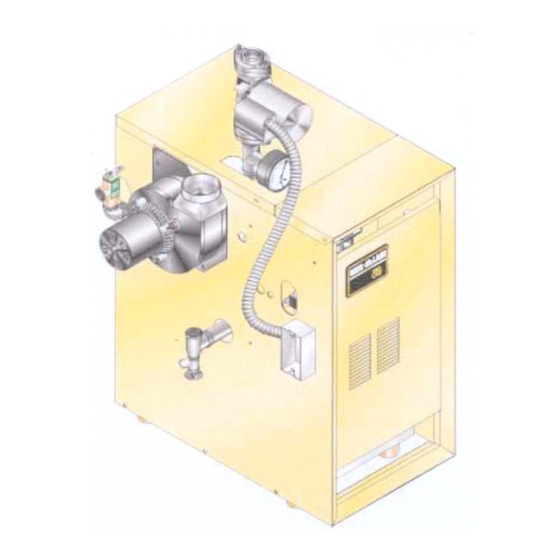
GOLD Series 2 Gas-Fired Water Boiler How it works . . . ① Control module The control module responds to signals from the room thermostat, air pressure switch and boiler limit circuit to operate the boiler circulator, pilot burner, gas valve and inducer. When room thermostat calls for heat, the control module starts the system circulator and inducer. -
Page 4: Table Of Contents
GOLD Series 2 Gas-Fired Water Boiler Contents How it works ..............2–3 Hazard definitions.............. 4 Please read before proceeding ......... 5 Prepare boiler location ..........6–11 Prepare boiler............. 12–13 Venting ................ 14-19 Water piping ............... 20-29 Gas piping ................ 30 Field wiring .............. -
Page 5: Please Read Before Proceeding
Boiler Manual Please read before proceeding Installer User • Read all instructions before This manual is for use only by your qualified Follow all instructions in installing. heating installer/service technician. proper order to prevent personal • Please refer to the User’s Information Manual injury or death. -
Page 6: Prepare Boiler Location
GOLD Series 2 Gas-Fired Water Boiler Prepare boiler location — codes & checklist Installations must • Local, state, provincial, and national codes, laws, regulations and follow these codes: ordinances. • National Fuel Gas Code, ANSI Z223.1–latest edition. • Standard for Controls and Safety Devices for Automatically Fired Boilers, ANSI/ASME CSD-1, when required. -
Page 7: Flooring And Foundation
Boiler Manual Prepare boiler location — clearances Provide the following clearances: Flooring and foundation 1. Hot water pipes — at least ½" from combustible Flooring materials. The CGi boiler is approved for installation on 2. Recommended service clearances — See Figure 1 combustible flooring, but must never be installed on carpeting. -
Page 8: Vent System
Do not operate a summer exhaust for condensation to occur. Condensation can fan. Close fireplace dampers. damage a masonry chimney. Weil-McLain recommends the following to prevent possible the appliance being inspected. Place in operation damage. - Page 9 Boiler Manual Prepare boiler location — contamination Air contamination Please review the following information on potential Refer to for products and areas which may cause Table 1 combustion air contamination problems. contaminated combustion air. If the boiler is installed in , or if products which any area likely to cause contamination would contaminate the air cannot be removed, you must either remove products permanently...
-
Page 10: Air Openings
GOLD Series 2 Gas-Fired Water Boiler Prepare boiler location — air openings Air directly from outside to boiler Combustion air and ventilation openings must comply room with Section 5.3, Air for Combustion and Ventilation , 1. Tightly constructed buildings must be provided of National Fuel Gas Code ANSI Z223.1–latest edition, with combustion and ventilation air openings to or applicable local building codes. - Page 11 Boiler Manual Special considerations Figure 5 Air from outdoors — vertical ducts Outside or ventilated attic Tight construction ANSI Z223.1 defines unusually tight construction Each opening free area = 1 sq. inch per 4,000 Btuh where: a. Walls and ceilings exposed to the outside atmosphere have a continuous water vapor retarder boiler with a rating of 1 perm or less with openings...
-
Page 12: Prepare Boiler
CGi-3 — CGi-8 2.70 mm 1.65 mm 0-2,000 ft 2,000-4,500 0-2,000 ft 2,000-4,500 Canada CGi-25 2.30 mm CGi-3 — CGi-8 2.70 mm 1.65 mm Note 1: For elevations above 2,000 feet, contact your local Weil-McLain sales office for details. Part Number 550-110-710/0200... -
Page 13: Prepare Boiler
Boiler Manual Prepare boiler — pressure test Perform hydrostatic pressure test Pressure test boiler attaching water or gas piping (except as noted below) or electrical before supply. Prepare boiler for test 1. Remove the shipping nipple (from CGi supply tapping) and remove the boiler relief valve. -
Page 14: Venting
GOLD Series 2 Gas-Fired Water Boiler Venting — general information with liner approved by the National Fuel Gas CGi venting methods Code, ANSI Z223.1–latest edition, or in Canada The CGi boiler can be vented using one of the following B149.1 or B149.2 Installation Code. methods: —... -
Page 15: Obtain Vent System Components
Note 1: Do not include termination fitting when counting total number of elbows. installation requirements. Table 5 Vent system components Description ® StaR-34 Z-Vent II FasNSeal™ Saf-T Vent Weil-McLain ® Saf-T Vent part number part number CGi Starter 699-999-015 73WMCGIS SRAWCG3 SVEWMFA03 FSA-WEIL-CGI... - Page 16 GOLD Series 2 Gas-Fired Water Boiler Venting — direct exhaust — vent starter 1. Select a vent pipe manufacturer and obtain all vent 3. Follow all applicable national, state, local or components needed, based on boiler location and provincial codes when venting the CGi boiler. venting method.
- Page 17 Boiler Manual Venting — direct exhaust — vent termination Follow instructions on this page when determining 12. Canadian installations — See B149.1 or B149.2 vent location to avoid possibility of severe personal Installation Code. Terminate vent no less than 6 feet injury, death or substantial property damage.
- Page 18 Vent is sloped toward termination as shown in dotted lines in Figure manufacturer's instructions for proper installation of vent runs, • The vent is installed per Weil-McLain and vent manufacturer’s including slope, support and instructions. condensate drainage. Condensate drippage from such vents may accumulate on the ground below.
- Page 19 Boiler Manual Using any termination other than one of those shown vertical or sidewall could cause nuisance outages and loss of heat, resulting in substantial property damage. Figure 15 Sidewall termination Termination elbow or tee Elbow and termination Pipe section coupling with screen Metal plate...
-
Page 20: Water Piping
GOLD Series 2 Gas-Fired Water Boiler Water piping — general information General piping information Circulator If installation is to comply with ASME or Canadian requirements, an The circulator is shipped loose (wiring pre-attached additional is needed. Install control in supply high temperature limit to boiler) to allow you to locate it either in the return piping between boiler and isolation valve. -
Page 21: Expansion Tank
Boiler Manual Water piping — single-zone system Expansion tank Diaphragm-type or bladder-type Closed-type expansion tank — expansion tank — Figure 16 Figure 17 1. Ensure expansion tank size will handle boiler and 1. Ensure expansion tank size will handle boiler and system water volume and temperature. - Page 22 130 °F regardless of system supply temperature. Contact your Weil-McLain representative for suggested piping and control methods. Failure to prevent cold return water temperature to the boiler could cause corrosion damage to the sections or burners, resulting in possible severe personal injury, death or substantial property damage.
- Page 23 Boiler Manual typical piping — multiple-zone installations Figure 18 Figure 19 Zoning with circulators Zoning with zone valves — return water 130 °F or higher. — return water 130 °F or higher. ZONE 2 ZONE 2 ZONE 1 ZONE 1 Alternate circulator location...
- Page 24 Contact water temperature no less than 130 °F your Weil-McLain representative for suggested piping and control methods. Failure to to the boiler could cause corrosion prevent cold return water temperature damage to the sections or burners, resulting in possible severe personal injury, death or substantial property damage.
- Page 25 Boiler Manual primary/secondary (preferred) bypass piping — for radiant heating or converted gravity systems Figure 20 Figure 21 Zoning with circulators Zoning with zone valves ZONE 2 ZONE 2 ZONE 1 ZONE 1 12" 12" MAX. MAX. Alternate Alternate circulator circulator location location...
- Page 26 Contact water temperature no less than 130 °F your Weil-McLain representative for suggested piping and control methods. Failure to to the boiler could cause corrosion prevent cold return water temperature damage to the sections or burners, resulting in possible severe personal injury, death or substantial property damage.
- Page 27 Boiler Manual boiler-bypass (alternate) piping — for radiant heating or converted gravity systems Figure 22 Boiler-bypass piping Figure 23 Boiler-bypass piping Zoning with circulators Zoning with zone valves (Alternative to primary/secondary piping (Alternative to primary/secondary piping Figures 20 and 21) Figures 20 and 21) ZONE 2 ZONE 2...
- Page 28 Contact water temperature no less than 130 °F your Weil-McLain representative for suggested piping and control methods. Failure to to the boiler could cause corrosion prevent cold return water temperature damage to the sections or burners, resulting in possible severe personal injury, death or substantial property damage.
- Page 29 Boiler Manual system-bypass (alternate) piping — for converted gravity (or steam) systems From system To system Figure 24 System-bypass piping Zoning with zone valve or circulators, return water 130 °F or higher. (Alternative to boiler-bypass piping Alternate Figures 22 and 23) circulator location System or zone circulator...
-
Page 30: Gas Piping
GOLD Series 2 Gas-Fired Water Boiler Gas piping Connecting gas supply piping to boiler Figure 26 Gas supply piping 1. Remove jacket front panel and refer to to pipe gas to boiler. Figure 26 at inlet of gas connection to boiler. Where local Install drip leg utility requires drip leg to be extended to the floor, use appropriate Manual main... -
Page 31: Field Wiring
Boiler Manual Field wiring For your safety, Thermostat turn off electrical power supply at service entrance panel before making any electrical 1. Connect thermostat as shown on wiring diagram to avoid possible electric shock hazard. connections on boiler. Failure to do so can cause severe personal injury or Install on inside wall away from influences of death. -
Page 32: Start-Up
GOLD Series 2 Gas-Fired Water Boiler Start-up — preparation Check for gas leaks — Your propane supplier mixes an odorant with the propane to make Propane boilers only its presence detectable. In some instances, the odorant can fade and the gas may no longer have an odor. - Page 33 Boiler Manual Fill the system with water 1. Close manual and automatic and boiler procedure until all zones are purged. air vents drain cock. g. Close the quick-fill water valve and purge valve and remove the hose. Open all isolation valves. Correct pressure Fill to correct system pressure.
-
Page 34: Start The Boiler
GOLD Series 2 Gas-Fired Water Boiler Start-up — operate boiler Final check before starting boiler • Read manual section , page 37, including the Operating instructions procedure ( , page 40). Figure 33 • Verify the boiler and system are full of water •... -
Page 35: Start-Up
Boiler Manual Check burner flames View pilot and main flames through the inspection port Figure 28 Typical pilot burner flame in the base burner shield. Inner Spark Pilot burner flame cone electrode pilot flame characteristics (see Proper Figure 28 1. Blue flame. 2. -
Page 36: Check-Out Procedure
GOLD Series 2 Gas-Fired Water Boiler Check-out procedure — checklist ❏ Boiler and heat distribution units filled with water? Pilot will relight, flame sensing element will sense pilot flame and main burners will reignite. ❏ Automatic air vent, if used, open one full turn? ❏... -
Page 37: Operation
Boiler Manual Operation — sequence on page 40. This generator activates and sequence returns to Read Operating instructions information is also located on a label on the inside step of the boiler jacket door panel. , control system If power is interrupted shuts pilot and main gas valves and restarts at step room thermostat to call for heat. -
Page 38: Wiring Diagrams
GOLD Series 2 Gas-Fired Water Boiler Operation — wiring diagrams Figure 31 Schematic wiring diagram 120 VAC — Neutral THERMOSTAT THERMOSTAT • The control module is polarity-sensitive to the incoming 120 VAC power. If polarity is reversed, FIELD control will flash the POWER light when powered SERVICE... - Page 39 Boiler Manual Figure 32 Ladder wiring diagram Part Number 550-110-710/0200...
- Page 40 GOLD Series 2 Gas-Fired Water Boiler Operation — operating instructions Figure 33 Operating instructions FOR YOUR SAFETY READ BEFORE OPERATING If you do not follow these instructions exactly, a fire or explosion may result causing property damage, personal injury or loss of life. A.
-
Page 41: Service And Maintenance
Boiler Manual Service and maintenance — schedule Table 8 Service and maintenance schedules Service technician Owner maintenance (see following pages for instructions) (see CGi User’s Information Manual for instructions) Inspect: • Check boiler area • Check air openings • Reported problems Daily •... - Page 42 GOLD Series 2 Gas-Fired Water Boiler Service and maintenance — annual start-up The boiler should be , at the beginning of the heating season, inspected and started annually only by a qualified . In addition, the maintenance and care of the boiler designated in and explained on service technician Table 8...
- Page 43 Boiler Manual ❏ Inspect ..Burners and base If insulation is damaged or displaced, do not operate the boiler. Replace or reposition insulation as necessary. Failure to replace damaged insulation can result in a fire hazard, causing severe personal injury, death or substantial property damage.
- Page 44 GOLD Series 2 Gas-Fired Water Boiler Service and maintenance — annual start-up (continued) ❏ Check/test ..Gas piping Expansion tank 1. Sniff near floor and around boiler area for any indication 1. Expansion tanks provide space for water to move in and of a out as the heating system water expands due to gas leak...
-
Page 45: Review With Owner
Boiler Manual ❏ ❏ Check/test ..Review with owner 1. Review the User’s Information Manual with the Boiler relief valve owner. Safety relief valves should be reinspected AT LEAST 2. Emphasize the need to perform the maintenance , by a licensed plumbing ONCE EVERY THREE YEARS schedule specified in the User’s Information... -
Page 46: Troubleshooting
Table 9 Pressure switch setpoint (for elevations above 2,000 Troubleshooting air pressure reading ft, contact your local Weil-McLain sales office for details.) 1. If manometer reading is lower than the setpoint of the switch (see ) — check for possible causes:... - Page 47 Boiler Manual Troubleshooting — components (continued) Control module POWER TSTAT CIRC lights flashing Usually indicates stray voltage on external thermostat circuit splatter between plugs and circuit wires (usually due to miswired 3-wire zone valve). Solder or water board can cause improper operation of control lights flashing POWER PRESS SWITCH...
- Page 48 GOLD Series 2 Gas-Fired Water Boiler Troubleshooting — components continued Figure 38 Control module connections Black Black 120 VAC H 120 VAC H Green Entrance ground High voltage to White pilot spark electrode Green Chassis SJO cable 120 VAC N ground to J-box 120 VAC to...
- Page 49 Does voltmeter indicate 24 VAC ? Have system checked by a licensed electrician. If Replace transformer. problem persists, call your Retest and check for back Boiler should now local Weil-McLain sales Replace control module. feed of voltage from operate normally. representative. Retest. system wiring.
- Page 50 GOLD Series 2 Gas-Fired Water Boiler Troubleshooting — control module lights CHART 2 — TSTAT CIRC & POWER lights flashing — Usually indicates 48 VAC on thermostat circuit (stray voltage) — ▲TURN OFF Electrical shock hazard — Wherever you see POWER▲, follow the instructions.
- Page 51 Boiler Manual continued CHART 3 — PRESS SWITCH & POWER lights flashing — Usually indicates pressure switch stuck closed or failed to make within 5 minutes — ▲TURN OFF Electrical shock hazard — Wherever you see POWER▲, follow the instructions. Failure to follow instructions could result in severe personal injury, death or substantial property damage.
- Page 52 GOLD Series 2 Gas-Fired Water Boiler Troubleshooting — control module lights CHART 4 — FLAME & POWER lights flashing — Usually indicates flame sensed when it shouldn't be there — ▲TURN OFF Electrical shock hazard — Wherever you see POWER▲, follow the instructions. Failure to follow instructions could result in severe personal injury, death or substantial property damage.
- Page 53 Boiler Manual continued CHART 5 — PRESS SWITCH light flashing and POWER light on steady — Usually indicates pressure switch opened during run cycle — — May also be caused by wind gusts in excess of 31 mph for non-direct vent sidewall-vented boilers — ▲TURN OFF Electrical shock hazard —...
- Page 54 GOLD Series 2 Gas-Fired Water Boiler Troubleshooting — control module lights (continued) CHART 6 — FLAME light flashing and POWER light on steady ALSO — Troubleshooting failure to establish main flame ▲TURN OFF Electrical shock hazard — Wherever you see POWER▲, follow the instructions.
- Page 55 Boiler Manual CHART 7 — Insufficient heat or no heat to system (POWER light on steady) ▲TURN OFF Electrical shock hazard — Wherever you see POWER▲, follow the instructions. Failure to follow instructions could result in severe personal injury, death or substantial property damage. •...
-
Page 56: Replacement Parts
Jacket assembly ..........Trim assembly ............. Gas control assembly ......... Replacement parts must be purchased through a local Weil-McLain distributor. When ordering, specify boiler model and size and include description and part number of replacement part. Results from using modified or other manufactured parts will not be covered by warranty and may damage boiler or impair operation. -
Page 62: Dimensions And Ratings
GOLD Series 2 Gas-Fired Water Boiler Dimensions Figure 44 Dimensional drawing Supply piping ( note 1 Gas supply piping 11¹⁄₈ Return piping ( note 1 Drain valve Relief valve, ¾" NPT Gas supply entrance (right or left side) ½" NPT to expansion tank/air vent Pressure/temperature gauge 3"... - Page 63 For alternate piping, contact your Weil-McLain sales office. CSA design certified for installation on combustible flooring. Tested for 50 psi working pressure.
- Page 64 GOLD Series 2 Gas-Fired Water Boiler — Boiler Manual Handling fiberglass and ceramic fiber materials REMOVAL OF COMBUSTION CHAMBER LINING OR BASE PANELS The combustion chamber lining or base insulation panels in this product contain ceramic fiber materials. Ceramic fibers can be converted to cristobalite in very high temperature applications. The International Agency for Research on Cancer (IARC) has concluded, "Crystalline silica inhaled in the form of quartz or cristobalite from occupational sources is carcinogenic to humans (Group 1).": ■...
Need help?
Do you have a question about the Gold CGi Series 2 and is the answer not in the manual?
Questions and answers