Weil-McLain Gold CGi 2 Series Manual
Gold cgi gas-fired water boilers series 2
Hide thumbs
Also See for Gold CGi 2 Series:
- Manual (68 pages) ,
- User manual (64 pages) ,
- Brochure & specs (6 pages)
Table of Contents
Advertisement
Quick Links
Boiler Manual
®
DO NOT USE BOILER DURING CONSTRUCTION
boiler area or follow the requirements given on page 9. Failure to comply could result in severe
personal injury, death or substantial property damage.
This manual must only be used by a qualified heating installer/service technician. BEFORE
installing, read all instructions in this manual and all other information shipped with the
boiler. Perform steps in the order given. Failure to comply could result in severe personal
injury, death or substantial property damage.
Gas-Fired Water Boilers
• Installation
• Startup
unless you provide dust-free air to the
Part number 550-110-710/1211
Series 2
• Maintenance
• Parts
Advertisement
Table of Contents

Subscribe to Our Youtube Channel
Related Manuals for Weil-McLain Gold CGi 2 Series


Summary of Contents for Weil-McLain Gold CGi 2 Series
- Page 1 ® Gas-Fired Water Boilers Series 2 Boiler Manual • Installation • Maintenance • Startup • Parts DO NOT USE BOILER DURING CONSTRUCTION unless you provide dust-free air to the boiler area or follow the requirements given on page 9. Failure to comply could result in severe personal injury, death or substantial property damage.
-
Page 2: How It Works
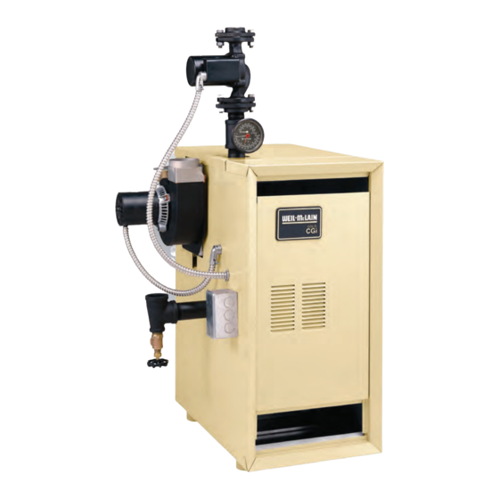
Boiler Manual GOLD GAS-FIRED WATER BOILER — SERIES 2 — How it works . . . ① Control module The control module responds to signals from the room thermostat, air pressure switch and boiler limit circuit to operate the boiler circulator, pilot burner, gas valve and inducer. When room thermostat calls for heat, the control module starts the system circulator and inducer. - Page 3 Boiler Manual GOLD GAS-FIRED WATER BOILER — SERIES 2 — GOLD CGi Gas-Fired Induced-Draft Water Boiler Part Number 550-110-710/1211...
-
Page 4: Table Of Contents
Boiler Manual GOLD GAS-FIRED WATER BOILER — SERIES 2 — Contents How it works ............2–3 Hazard definitions ..........4 Please read before proceeding ......5 Prepare boiler location ........6–11 Prepare boiler ..........12–13 Venting ............14-19 Water piping ..........20-29 Gas piping ............30 Field wiring ............ -
Page 5: Please Read Before Proceeding
Boiler Manual GOLD GAS-FIRED WATER BOILER — SERIES 2 — Please read before proceeding Installer User Read all instructions before in- This manual is for use only by your qualified • stalling . Follow all instructions in heating installer/service technician. proper order to prevent personal User’s Information Manual •... - Page 6 Boiler Manual GOLD GAS-FIRED WATER BOILER — SERIES 2 — Prepare boiler location — codes & checklist Installations must follow these codes: • Local, state, provincial, and national codes, laws, regulations and ordinances. • National Fuel Gas Code, ANSI Z223.1 –– latest edition. •...
-
Page 7: Prepare Boiler Location
Boiler Manual GOLD GAS-FIRED WATER BOILER — SERIES 2 — Prepare boiler location — clearances Recommended SERVICE clearances Figure 1b Required MINIMUM clearances (Fig. 1a) 1. Provide clearances for cleaning and servicing the boiler and for access to controls and components. See Figure 1a for recommen- dations. -
Page 8: Prepare Boiler
Condensation properly vents when tested as outlined above, return can damage a masonry chimney. Weil-McLain doors, windows, exhaust fans, fireplace dampers, and recommends the following to prevent possible any other gas-burning appliance to their previous con- damage. - Page 9 Boiler Manual GOLD GAS-FIRED WATER BOILER — SERIES 2 — Prepare boiler location — air contamination Table 1 Please review the following information on potential Refer to for products and areas which may cause combustion air contamination problems. contaminated combustion air. To prevent potential of severe personal injury or death, check for products or areas listed below before installing boiler.
- Page 10 Boiler Manual GOLD GAS-FIRED WATER BOILER — SERIES 2 — Prepare boiler location — air openings Figure 2 Air openings to interior spaces Combustion air opening location and sizing requirements depend on the clearances around ✷ the boiler. Check the boiler placement compared to ✷...
- Page 11 Boiler Manual GOLD GAS-FIRED WATER BOILER — SERIES 2 — Unusually tight construction FREE AREA of openings — the minimum areas Unusually tight construction means (per ANSI Z223.1) given in this manual are free area (equals the area, buildings in which: length times width of opening, after deduction for louver obstruction).
- Page 12 2,000-4,500 Canada CGi-25 2.30 mm CGi-3 and CGi-5 2.55 mm 1.60 mm 1.45 mm CGi-4, CGi-6 - CGi-8 2.70 mm 1.65 mm Note 1: For elevations above 2,000 feet, contact your local Weil-McLain sales office for details. Part Number 550-110-710/1211...
- Page 13 Boiler Manual GOLD GAS-FIRED WATER BOILER — SERIES 2 — Prepare boiler — pressure test Hydrostatic pressure test 5. Slowly reopen boiler drain valve until test pressure on the pressure/temperature gauge reaches no more before Pressure test boiler attaching water or gas piping than: (except as noted below) or electrical supply.
-
Page 14: Venting
Boiler Manual GOLD GAS-FIRED WATER BOILER — SERIES 2 — Venting — general information CGi venting methods — Chimney draft or Direct exhaust Chimney draft venting Direct exhaust — vertical or sidewall Chimney draft venting uses the natural draft provided Direct exhaust venting uses inside combustion air with by a vertical vent or chimney. -
Page 15: Obtain Vent System Components
Boiler Manual GOLD GAS-FIRED WATER BOILER — SERIES 2 — Venting — Direct exhaust — components Obtain vent system components Table 4 Maximum vent length 1. The following special gas vent systems comply with UL-1738 and ULC-S636 standards and are certified by CSA as the only Max. - Page 16 Boiler Manual GOLD GAS-FIRED WATER BOILER — SERIES 2 — Venting — direct exhaust — vent starter 1. Select a vent pipe manufacturer and obtain all vent 3. Follow all applicable national, state, local or provin- components needed, based on boiler location and cial codes when venting the CGi boiler.
- Page 17 Boiler Manual GOLD GAS-FIRED WATER BOILER — SERIES 2 — Venting — direct exhaust — termination Follow instructions on this page 12. Canadian installations — See B149.1 or B149.2 when determining vent location to Installation Code. Terminate vent no less than 6 avoid possibility of severe personal feet from another combustion air inlet, 3 feet from injury, death or substantial property...
- Page 18 • Vent is sloped toward termination as shown in dotted lines in Figure 14 • The vent is installed per Weil-McLain and vent manufacturer’s instructions. • Condensate drippage from such vents may accumu- late on the ground below. Consider traffic in the area to avoid hazard due to ice accumulation.
-
Page 19: Venting
Boiler Manual GOLD GAS-FIRED WATER BOILER — SERIES 2 — Venting — direct exhaust — installation (cont.) Using any termination other than one of those shown Figure 15 Sidewall termination could cause nuisance outages and loss of heat, resulting in substantial property damage. Part Number 550-110-710/1211... -
Page 20: Water Piping
Boiler Manual GOLD GAS-FIRED WATER BOILER — SERIES 2 — Water piping — general information General piping information Circulator If installation is to comply with ASME or Canadian requirements, an ad- The circulator is shipped loose (wiring pre-attached to ditional high temperature limit is needed. - Page 21 Boiler Manual GOLD GAS-FIRED WATER BOILER — SERIES 2 — Water piping — single-zone system Undersized expansion tanks cause system water to be lost from relief valve and makeup water to be added through fill valve. Eventual section failure can result. Diaphragm-type or bladder- Closed-type expansion tank type expansion tank...
-
Page 22: Piping Multiple Zones
. Instead, provide controls and piping which can regulate the boiler return water temperature at no less than 130°F regardless of system supply temperature. Contact your Weil-McLain representative for suggested piping and control methods. Failure to prevent cold return water temperature to the boiler could cause corrosion damage to the sections or burners, resulting in possible severe personal injury, death or substantial property damage. - Page 23 Boiler Manual GOLD GAS-FIRED WATER BOILER — SERIES 2 — Water piping — multiple zones (continued) Figure 18 Figure 19 Zoning with circulators Zoning with zone valves — return water 130°F or higher. — return water 130°F or higher. Boiler isolation (balancing) valves Automatic air vent (with diaphragm-type expansion tank), or con- nect to tank fitting (closed-type expansion tank).
-
Page 24: Temperature Gauges
130°F regardless of system supply temperature. Contact your Weil-McLain representative for suggested piping and control methods. prevent cold return water temperature Failure to to the boiler could cause corrosion damage to the sections or burners, resulting in possible severe personal injury, death or substantial property damage. - Page 25 Boiler Manual GOLD GAS-FIRED WATER BOILER — SERIES 2 — Piping — low temperature systems (continued) Figure 20 Figure 21 Primary/secondary piping Primary/secondary piping Zoning with circulators Zoning with zone valves Boiler isolation (balancing) valves Relief valve Automatic air vent (with diaphragm-type expansion tank), or Flow/check valve DO NOT connect to tank fitting (closed-type expansion tank).
- Page 26 130°F regardless of system supply temperature. Contact your Weil-McLain representative for suggested piping and control methods. prevent cold return water temperature Failure to to the boiler could cause corrosion damage to the sections or burners, resulting in possible severe personal injury, death or substantial property damage.
- Page 27 Boiler Manual GOLD GAS-FIRED WATER BOILER — SERIES 2 — Piping — low temperature systems (continued) Figure 22 Boiler-bypass piping — Zoning with Figure 23 Boiler-bypass piping — Zoning with circulators — (Alternative to primary/ zone valves — (Alternative to primary/ secondary piping Figures 20 and 21) secondary piping Figures 20 and 21) Boiler isolation (balancing) valves...
- Page 28 130°F regardless of system supply temperature. Contact your Weil-McLain representative for suggested piping and control methods. prevent cold return water temperature Failure to to the boiler could cause corrosion damage to the sections or burners, resulting in possible severe personal injury, death or substantial property damage.
- Page 29 Boiler Manual GOLD GAS-FIRED WATER BOILER — SERIES 2 — Piping — low temperature systems (continued) Figure 24 System-bypass piping — Zoning with zone valve or circulators, return water 130°F or higher — (Alternative to boiler- bypass piping Figures 22 and 23) 3 System or zone circulator 7 System temperature valves (see instructions to the left for adjusting valves)
-
Page 30: Gas Piping
Boiler Manual GOLD GAS-FIRED WATER BOILER — SERIES 2 — Gas piping Connecting gas supply piping to boiler Natural Gas: 1. Remove jacket front panel and refer to Figure 26 to pipe gas to boiler. 1. Refer to Table 7 for pipe length and diameter. -
Page 31: Field Wiring
Boiler Manual GOLD GAS-FIRED WATER BOILER — SERIES 2 — Field wiring Thermostat turn off electrical power supply at For your safety, service entrance panel before making any electrical 1. Connect thermostat as shown on wiring diagram connections to avoid possible electric shock hazard. on boiler. -
Page 32: Start-Up
Boiler Manual GOLD GAS-FIRED WATER BOILER — SERIES 2 — Start-up — preparation Check for gas leaks Determine if water treatment is needed Before starting the boiler, and dur- petroleum-based cleaning or sealing Do not use ing initial operation, smell near the compounds in boiler system. - Page 33 Boiler Manual GOLD GAS-FIRED WATER BOILER — SERIES 2 — Start-up — preparation (continued) Fill the system with water Inspect system water piping air vents 1. Close manual and automatic and boiler drain cock. After filling the boiler and system with water, inspect all piping throughout the system for leaks.
-
Page 34: Start The Boiler
Boiler Manual GOLD GAS-FIRED WATER BOILER — SERIES 2 — Start-up — operate boiler If you discover evidence of any DO NOT proceed with boiler gas leak, shut down the boiler operation unless boiler and at once. Find the leak source system have been filled with with bubble test and repair im- water and all instructions and... - Page 35 Boiler Manual GOLD GAS-FIRED WATER BOILER — SERIES 2 — Start-up — operate boiler (continued) Check burner flames Figure 28 Typical pilot burner flame View pilot and main flames through the inspection port in the base burner shield. Pilot burner flame ( Figure 28 PROPER pilot flame characteristics 1.
-
Page 36: Check-Out Procedure - Checklist
Boiler Manual GOLD GAS-FIRED WATER BOILER — SERIES 2 — Check-out procedure — checklist ❏ Boiler and heat distribution units filled with water? ❏ For multiple zones, adjust flow so it is about the same in each zone. ❏ Automatic air vent, if used, open one full turn? ❏... -
Page 37: Operation
Boiler Manual GOLD GAS-FIRED WATER BOILER — SERIES 2 — Operation — sequence Read Operating instructions on page 40. This erator activates and sequence returns to step information is also located on a label on the inside If power is interrupted , control system shuts of the boiler jacket door panel. - Page 38 Boiler Manual GOLD GAS-FIRED WATER BOILER — SERIES 2 — Operation — wiring diagrams Figure 31 Schematic wiring diagram Part Number 550-110-710/1211...
- Page 39 Boiler Manual GOLD GAS-FIRED WATER BOILER — SERIES 2 — Operation — wiring diagrams (continued) Figure 32 Ladder wiring diagram Part Number 550-110-710/1211...
-
Page 40: C Operating Instructions
Boiler Manual GOLD GAS-FIRED WATER BOILER — SERIES 2 — Operating instructions • Spark pilot • Natural or propane gas CGi-25 to CGi-6 • Gas valve: Honeywell VR8204/VR8304 Part Number 550-110-710/1211... - Page 41 Boiler Manual GOLD GAS-FIRED WATER BOILER — SERIES 2 — Operating instructions • Spark pilot • Natural or propane gas CGi-25 to CGi-6 • Gas valve: White-Rodgers 36E Part Number 550-110-710/1211...
- Page 42 Boiler Manual GOLD GAS-FIRED WATER BOILER — SERIES 2 — Operating instructions • Spark pilot • Natural or propane gas CGi-25 to CGi-8 • Gas valve: White-Rodgers 36C Part Number 550-110-710/1211...
-
Page 43: Service And Maintenance
Boiler Manual GOLD GAS-FIRED WATER BOILER — SERIES 2 — Service and maintenance — schedule VERIFY PROPER OPERATION AFTER SERVICING Table 8 Service and maintenance schedules Service technician Owner maintenance (see following pages for instructions) (see CGi User’s Information Manual for instructions) •... -
Page 44: Air Openings
Boiler Manual GOLD GAS-FIRED WATER BOILER — SERIES 2 — Service and maintenance — annual start-up Air openings 1. Verify that combustion and ventilation air openings inspected and started annu- The boiler should be to the boiler room and/or building are open and ally , at the beginning of the heating season, only... - Page 45 Boiler Manual GOLD GAS-FIRED WATER BOILER — SERIES 2 — Service & maintenance – annual start-up (cont.) ❏ Inspect . . . burner inlet while cleaning the burner ports with a wire brush. The vacuum will help to draw any airborne material out of the burner. 4.
-
Page 46: Expansion Tank
Boiler Manual GOLD GAS-FIRED WATER BOILER — SERIES 2 — Service & maintenance – annual start-up (cont.) ❏ Check/test . . . an out as the heating system water expands due to temperature increase or contracts as the water cools. Tanks may be open, closed or diaphragm or bladder Gas piping type. -
Page 47: Review With Owner
Boiler Manual GOLD GAS-FIRED WATER BOILER — SERIES 2 — Service & maintenance – annual start-up (cont.) ❏ Review with owner reinspected AT LEAST Safety relief valves should be ONCE EVERYTHREEYEARS , by a licensed plumb- 1. Review the User’s Information Manual with the ing contractor or authorized inspection agency, to owner. -
Page 48: Troubleshooting
Boiler Manual GOLD GAS-FIRED WATER BOILER — SERIES 2 — Troubleshooting — procedure Label all wires prior to disconnection when servicing Check the following: controls. Wiring errors can cause improper and danger- 1. Wire connectors to control module are se- ous operation. - Page 49 Boiler Manual GOLD GAS-FIRED WATER BOILER — SERIES 2 — Troubleshooting — components (continued) POWER light flashing alone Figure 36 Manometer connections Usually indicates reversed polarity of 120 VAC power wires. POWER and TSTAT CIRC lights flashing Usually indicates stray voltage on external thermostat circuit wires (usually due to miswired 3-wire zone valve).
- Page 50 Boiler Manual GOLD GAS-FIRED WATER BOILER — SERIES 2 — Troubleshooting — components (continued) Figure 38 Control module connections Part Number 550-110-710/1211...
- Page 51 Does voltmeter indicate Have system checked by a licensed electrician. If Replace transformer. problem persists, call your Retest and check for back Boiler should now local Weil-McLain sales Replace control module. feed of voltage from operate normally. representative. Retest. system wiring.
- Page 52 Boiler Manual GOLD GAS-FIRED WATER BOILER — SERIES 2 — Troubleshooting — control module lights (cont.) Electrical shock hazard — Wherever you see sTURN OFF POWERs, follow the instructions. Failure to follow instructions could result in severe personal injury, death, or substantial property damage. Part Number 550-110-710/1211...
- Page 53 Boiler Manual GOLD GAS-FIRED WATER BOILER — SERIES 2 — Troubleshooting — control module lights (cont.) CHART 3 — PRESS SWITCH & POWER lights flashing — Usually indicates pressure switch stuck closed or failed to make within 5 minutes — Electrical shock hazard —...
- Page 54 Boiler Manual GOLD GAS-FIRED WATER BOILER — SERIES 2 — Troubleshooting — control module lights (cont.) Part Number 550-110-710/1211...
- Page 55 Boiler Manual GOLD GAS-FIRED WATER BOILER — SERIES 2 — Troubleshooting — control module lights (cont.) CHART 5 — PRESS SWITCH light flashing and POWER light on steady — Usually indicates pressure switch opened during run cycle — — May also be caused by wind gusts in excess of 31 mph for non-direct vent sidewall-vented boilers — Electrical shock hazard —...
- Page 56 Boiler Manual GOLD GAS-FIRED WATER BOILER — SERIES 2 — Troubleshooting — control module lights (cont.) Part Number 550-110-710/1211...
- Page 57 Boiler Manual GOLD GAS-FIRED WATER BOILER — SERIES 2 — Troubleshooting — control module lights (cont.) — Insufficient heat or no heat to system (POWER light on steady) Electrical shock hazard — Wherever you see sTURN OFF POWERs, follow the instructions. Failure to follow Electrical shock hazard —...
-
Page 58: Replacement Parts
Jacket .............. 62 Trim ..............63 Controls ............64 Replacement parts must be purchased through a local Weil-McLain distributor. When ordering, specify boiler model and size and include description and part number of replacement part. Results from using modified or other manufactured parts will not be covered by warranty and may damage boiler or impair operation. - Page 59 Boiler Manual GOLD GAS-FIRED WATER BOILER — SERIES 2 — Replacement parts — section assembly Figure 39 Section assembly Item Description Weil-McLain Item Description Weil-McLain number part number number part number End section, left hand, 51124 311-103-850 Washer, M⁄zn” (1 per tie rod)
- Page 60 Boiler Manual GOLD GAS-FIRED WATER BOILER — SERIES 2 — Replacement parts — base Figure 40 Base assembly Part Number 550-110-710/1211...
- Page 61 Boiler Manual GOLD GAS-FIRED WATER BOILER — SERIES 2 — Replacement parts — base (continued) Weil-McLain Item Description part number Base assembly kit CGi-25 & CGi-3 381-354-337 (includes base panels items 1, 2, 3, 4, 5, 6 CGi-4 381-354-338 and 7)
- Page 62 Panel, left side, Panel, right side, Panel, top front, Panel, top rear, with insulation with insulation with insulation with insulation Natural Gas Propane Gas Boiler Boiler Weil-McLain part number Model Model CGi-25 (Available at local 381-355-534 381-355-581 381-355-699 381-355-403 381-355-539 CGi-25 CGi-3...
- Page 63 Boiler Manual GOLD GAS-FIRED WATER BOILER — SERIES 2 — Replacement parts — trim Figure 42 Trim assembly Item Description Manufacturer Manufacturer’s Weil-McLain number part number part number Pressure relief valve, ASME, 30 PSIG, ¾” male inlet Conbraco 10-407-05 511-546-920 Watts M330 Pressure relief valve, ASME, 30 PSIG, ¾”...
-
Page 64: Replacement Parts
GAS-FIRED WATER BOILER — SERIES 2 — Replacement parts — controls Figure 43 Gas control assembly Item Description Boiler model Manufacturer Manufacturer’s Weil-McLain number part number part number Natural gas components Gas valve, ½” x ½” CGi-25 -- CGi-6 Honeywell... -
Page 65: Dimensions And Ratings
Boiler Manual GOLD GAS-FIRED WATER BOILER — SERIES 2 — Dimensions Figure 44 Dimensional drawing Boiler Supply Return “W” model tapping tapping connection size manifold size Jacket number (inches NPT) (inches NPT) Note 3 Note 3 width (inches NPT) (inches NPT) (inches) CGi-25 1 ¼... - Page 66 Vent diameter shown above is for direct exhaust venting. See Table 3, page 14, for vent diameter when chimney draft venting. As an Energy Star Partner, Weil-McLain has determined that the CGi-3 meets the Energy Star guidelines for energy efficiency.
-
Page 67: Handling Ceramic Fiber And Fiberglass Materials
Boiler Manual GOLD GAS-FIRED WATER BOILER — SERIES 2 — Handling ceramic fiber and fiberglass materials REMOVAL OF COMBUSTION CHAMBER REMOVAL OF FIBERGLASS WOOL LINING OR BASE PANELS The combustion chamber lining or base INSTALLATION OF FIBERGLASS WOOL, insulation panels in this product con- COMBUSTION CHAMBER LINING OR tain ceramic fiber materials. - Page 68 Boiler Manual GOLD GAS-FIRED WATER BOILER — SERIES 2 — Part Number 550-110-710/0409 Part number 550-110-710/1211...
Need help?
Do you have a question about the Gold CGi 2 Series and is the answer not in the manual?
Questions and answers