
Related Manuals for Brocade Communications Systems Encryption Switch


Summary of Contents for Brocade Communications Systems Encryption Switch
- Page 1 53-1001118-01 18 August 2008 Brocade Encryption Switch QuickStart Guide Supporting Fabric OS v6.1.1_enc 53-1001118-01 *53-1001118-01* 18 August 2008...
- Page 2 The authors and Brocade Communications Systems, Inc. shall have no liability or responsibility to any person or entity with respect to any loss, cost, liability, or damages arising from the information contained in this book or the computer programs that accompany it.
-
Page 3: Table Of Contents
Overview This QuickStart guide is intended as an overview to help experienced installers unpack, install, and configure a Brocade Encryption Switch quickly. For detailed installation and configuration instructions, refer to the Brocade Encryption Switch Hardware Reference Manual. This guide include these topics. -
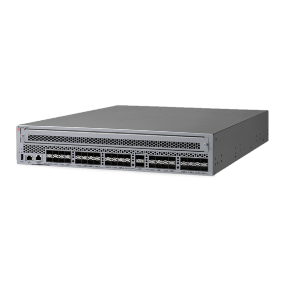
Page 4: Port Side Of The Switch
Power LED RJ45 GE ports (for clustering and re-keying) Smart Card reader RJ45 GE management port RJ45 Serial console port USB port Fibre Channel ports (0 - 31) FIGURE 1 Port-side view 4 of 20 Encryption Switch QuickStart Guide 53-1001118-01... -
Page 5: Port Numbering
3) includes the two redundant power supply FRUs, three redundant fan assembly FRUs, and their status LEDs. Power supply (2) Power supply status LED Fan (3) Fan status LED FIGURE 3 Non-port side view Encryption Switch QuickStart Guide 5 of 20 53-1001118-01... -
Page 6: Field-Replaceable Units (Frus)
The power supply FRUs are identical and interchangeable; the fan assembly FRUs are also identical and interchangeable. Power-cord connection Power supply status LED Power switch Captive screw FIGURE 4 Power supply 6 of 20 Encryption Switch QuickStart Guide 53-1001118-01... - Page 7 Captive screw Fan status LED FIGURE 5 Fan assembly Encryption Switch QuickStart Guide 7 of 20 53-1001118-01...
-
Page 8: Time And Items Required
Time and items required You can set up and install the Brocade Encryption Switch in the following ways: • As a standalone unit on a flat surface. • In a 19-in. Electronic Industries Association (EIA) cabinet, using the Fixed Rack Mount Kit (optional) or Slide Rack Mount Kit (optional). -
Page 9: Site Preparation And Installation Guidelines
A USB stick for collecting supportsave output data (optional) • SFPs and compatible cables NOTE For information about the SFP transceivers that are qualified for the Brocade Encryption Switch, go to http://www.brocade.com/products/interop_and_compatibility.jsp. Encryption Switch QuickStart Guide 9 of 20 53-1001118-01... -
Page 10: Items Included With The Switch
Items included with the switch The following items are included with the standard shipment of the switch. • The Brocade Encryption Switch, containing two power supplies and three fan assemblies • One accessory kit containing: • Serial cable with an RJ-45 connector. -
Page 11: Configuring The Switch
Managing cables ..........19 Encryption Switch QuickStart Guide... - Page 12 FIGURE 6 Switch configuration 12 of 20 Encryption Switch QuickStart Guide 53-1001118-01...
-
Page 13: Logging In To The Serial Console Port
2. When the terminal emulator application stops reporting information, press Enter to display the login prompt. 3. Log in to the switch as admin, using the default password: password. You are prompted to change the default passwords at initial login. Encryption Switch QuickStart Guide 13 of 20 53-1001118-01... -
Page 14: Setting The Ip Address
3. Open a Telnet session on the workstation. NOTE The following information describes using the CLI but these tasks can be performed using Brocade’s Web Tools product or Brocade’s licensed DCFM Enterprise product. 14 of 20 Encryption Switch QuickStart Guide... -
Page 15: Setting The Domain Id
MM is minutes; valid values are 00 through 59. • yy is the year; valid values are 00 through 99 (values greater than 69 are interpreted as 1970 through 1999, and values less than 70 are interpreted as 2000-2069). Encryption Switch QuickStart Guide 15 of 20 53-1001118-01... -
Page 16: Setting The Time Zone
NTP server. The rest will be stored as backup servers that can take over if the active NTP server fails. The principal or primary FCS switch synchronizes its time with the NTP server every 64 seconds. 16 of 20 Encryption Switch QuickStart Guide 53-1001118-01... -
Page 17: Verifying Correct Operation And Backing Up The Configuration
2. Ensure that the bail (wire handle) is in the unlocked position. Place the SFP in the correct position on the port (Figure 3. Slide the SFP into the port until it clicks into place. Close the bail. Encryption Switch QuickStart Guide 17 of 20 53-1001118-01... - Page 18 Repeat Step a for the remaining cables. 5. Check the LEDs to verify that all components are functional. 6. Verify the correct operation of the switch by entering the switchShow command from the workstation. 18 of 20 Encryption Switch QuickStart Guide 53-1001118-01...
-
Page 19: Managing Cables
Refer to the Fabric OS Encryption Administrator’s Guide for the procedures to configure the encryption functions. Summary of procedure If the Brocade Encryption Switch is being configured for the first time for encryption services, you will need to perform several pre-initialization tasks related to configuring the encryption node (switch), including: •... - Page 20 After completing the pre-initialization tasks, you may need to perform several tasks related to configuring the encryption group. Figure 8 summarizes the flow of the encryption-configuration tasks. FIGURE 8 Encryption configuration 20 of 20 Encryption Switch QuickStart Guide 53-1001118-01...
Need help?
Do you have a question about the Encryption Switch and is the answer not in the manual?
Questions and answers